MODULE OVERVIEW
The 7125 module is a dual-rate, serial digital distribution amplifier with automatic cable
equalization and reclocking. It automatically detects and handles 270 Mb/s Standard
Definition signals (525 or 625), 1.485 Gb/s High Definition signals, ASI data signals, and
allows passing of embedded audio. The module provides two DAs on the one module with
two sets of one serial digital input to four serial digital video outputs.
As shown in the block diagram below, the serial input signal passes through a serial
equalizer circuit where cable equalization and input monitoring is done. This output
signal then passes to a reclocking circuit. Here the serial input signal is locked to a local
serial clock removing timing noise and improving jitter performance.
The output of the reclocker circuit feeds into output drivers which provide four HD or SD
SDI serial digital outputs to the rear BNCs for distribution. When an ASI input is used
two outputs are provided.
Power is derived from the ± 12 volt frame power. It is regulated to the required +5 volts
for the module by on-board regulator. The module is fused with a resettable fuse device.
If the fuse opens due to an overcurrent condition, the module will lose power. After pulling
the module, the fuse will reset automatically requiring no replacement fuse.
The on-board CPU can monitor and report module ID information (slot location, software
version and board revision), power status, and ancillary data status to the optional frame
System Control module. This information can be accessed by the user or set to register an
alarm if desired using the remote control options available.
Modules at software version 2.2.0 or later support SNMP (Simple Network Management
Protocol) monitoring. For each applicable signal processing module, module, signal, and
reference status are reported. For complete details on using SNMP monitoring, refer to
the Avenue System Overview in the manual that accompanies each frame.
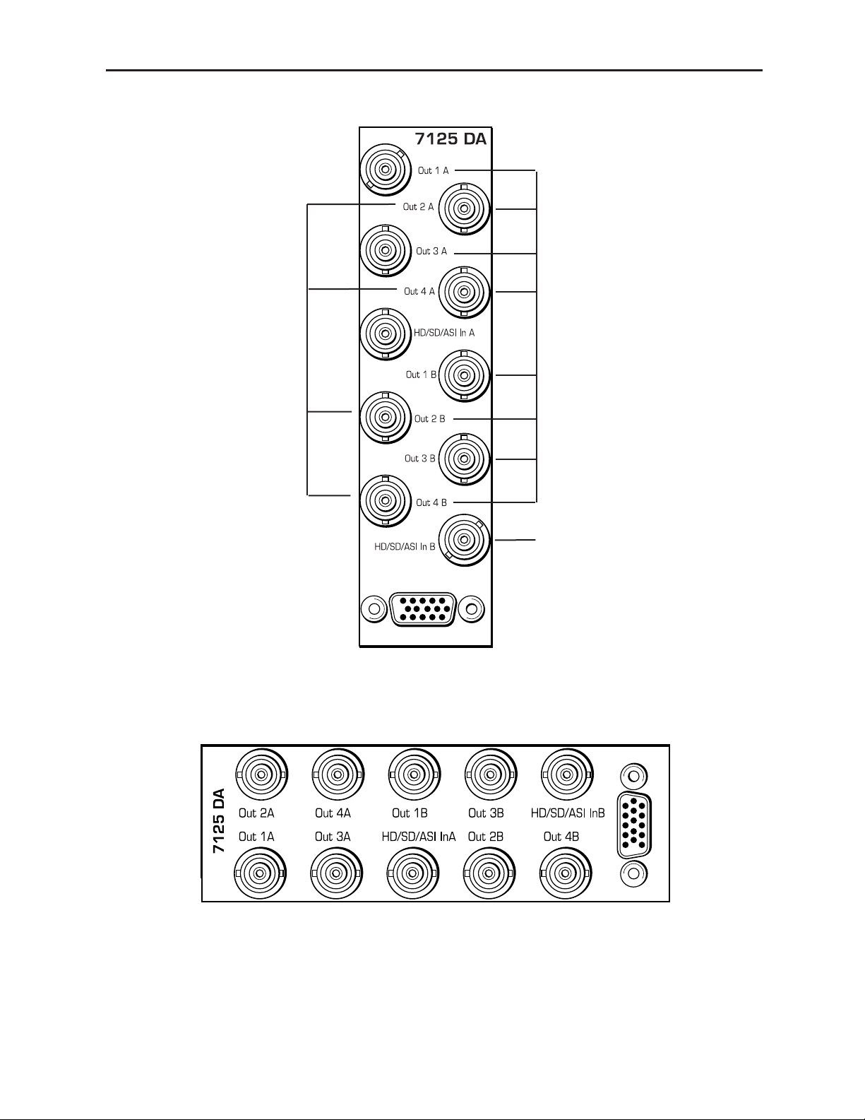
Model 7125 SD/HD/ASI Reclocking DA
7125 HD/SD/ASI Dual Reclocking DA Functional Block Diagram
7125-2