AVGear AVG-MA1 User manual
Features
2x20Watt@4Ohm as the default amplifier output.
Bridge connection function. The user can switch the MA1 to be
1x40Watt@8Ohm using the bridge connection.
Dual-mono function. The user can sum the stereo audio to dual mono
audio.
Microphone mixer function. The microphone will be mixed with the line
audio output, with independent level control.
48volt microphone power available at Mic Input.
Ducking power technology. It monitor’s the incoming audio and MIC
input, and reduces the power consumption when there is no audio
present.
Two stereo audio inputs, switchable by panel button or RS232.
Volume/Bass/Treble controllable by panel buttons or RS232
Line audio output, with adjustable volume.
Optional control solution, by IR remote or volume panel.
RS232 controlling built in with smart feedback.
Antistatic case design: providing good protection for long-term
and stable performance
Internal international power supply (100Volt~240Volt AC,
50/60Hz) for worldwide compatibility.
Fast switching speed.
MA1 is a small digital amplifier (Class-D), with EQ control and MIC mixer function.
AVG-MA1
PLEASE READ THIS PRODUCT MANUAL CAREFULLY
BEFORE USING THIS PRODUCT.
This manual is only for operation instruction only,
and not to be used in a maintenance capacity.
The functions described in this version are
current till March 2015. Any changes of functions
and operational parameters will be updated in
future manual versions. Please refer to your
dealer for the latest product details.
Version 1.0 1/3/15

AVG-MA1
SAFETY OPERATION GUIDE
In order to guarantee the reliable operation of the equipment and
safety of the user,please abide by the following procedures in
installation, use and maintenance:
1. The system must be earthed properly. Please do not use
two blade plugs and ensure the alternating power supply
ranges from 100v to 240v and from 50Hz to 60Hz.
2. Do not install the switcher in an environment where it will be
exposed to hot or cold temperatures.
3. This unit will generate heat during operation, please ensure
that you allow adequate ventilation to ensure reliable
operation.
4. Please disconnect the unit from mains power if it will be left
unused for a long time.
5. Please DO NOT try to open the casing of the equipment,
DO NOT attempt to repair the unit. Opening the unit will void
the warranty. There are high voltage components in the unit
and attempting to repair the unit could result in serious
injury.
6. Do not allow the unit to come into contact with any liquid as
that could result in personal injury and product failure.
AVG-MA1
1. Introduction
MA1 is a small digital amplifier (Class-D), with EQ control and MIC mixer function. It is
compact in size but incorporates powerful functions, including the bridge connection, dual-
mono, EQ control, microphone mixer etc.
It is extremely useful in applications, including classroom, small meeting rooms, lecture
halls, bars, pubs etc.
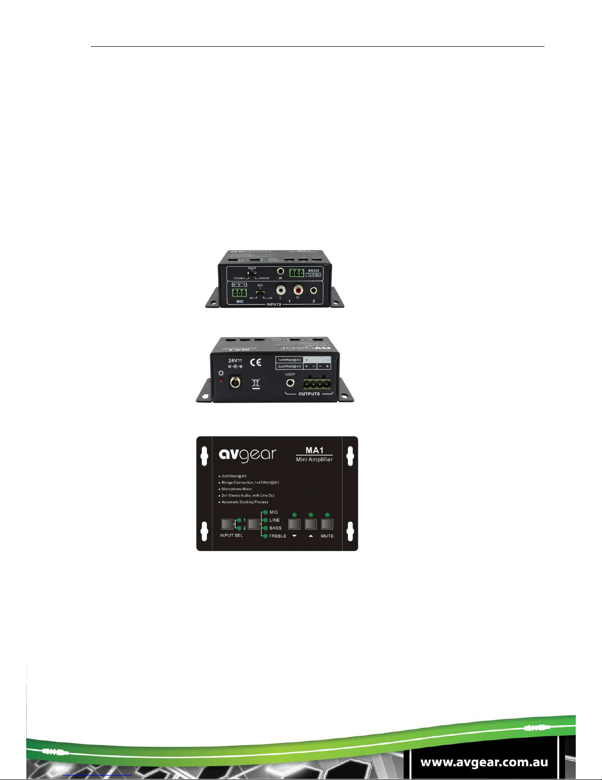
Front Panel
Rear Panel
Top Panel

AVG-MA1
1.1 Features
2x20Watt@4Ohm as the default amplifier output.
Bridge connection function. The user can switch the MA1 to be 1x40Watt@8Ohm using the
bridge connection.
Dual-mono function. The user can sum the stereo audio to dual mono audio.
Microphone mixer function. The microphone will be mixed with the line audio output,
with independent level control.
48volt microphone power available at Mic Input.
Ducking power technology. It monitor’s the incoming audio and MIC input, and
reduces the power consumption when there is no audio present.
Two stereo audio inputs, switchable by panel button or RS232.
Volume/Bass/Treble controllable by panel buttons or RS232
Line audio output, with adjustable volume.
Optional control solution, by IR remote or volume panel.
RS232 controlling built in with smart feedback.
Antistatic case design: providing good protection for long-term and stable performance
Internal international power supply (100Volt~240Volt AC, 50/60Hz) for worldwide
compatibility.
Fast switching speed.
LED indicator, for power and working status.

AVG-MA1
2. WHATS IN THE BOX
1 x MA1
2 x Captive Screw Connector
1 x RS232 Cable with Phoenix Connector
1 x Power adapter (DC24V)
4 x Plastic Feet
1 x Power Cord
1 x User manual
Note:Please confirm that the product and the accessories are all included, if not, please
contact your dealer.

AVG-MA1
3. Connecting the MA1
3.1 Stereo output: 2x20Watt@4Ohm
The default output of amplifier is 2x20Watt@4Ohm. So, the user can connect the amplifier
output in the regular way. As the picture below:
3.2 Bridged output connection: 1x40Watt@8Ohm
The MA1 has the bridge connection, to double the output power at 1x40Watt@8Ohm. It will
sum up the input left channel and input right channel to be mono output, and the power is
up to 40Watt.
The bridge connection is:
3.3 Dual-mono output:
The MA1 also has the function of double-mono output. It can sum up the left and right
channel, to be the mono audio output. In this way, the both of the outputs are showing the
same mono audio.
The connection is:
1x40Watt@8Ohm
2x20Watt@4Ohm
Switching to the
“STEREO”
Switching to the
“BRIDGE”
Connecting the two pins, like this
Connecting the four pins, like this
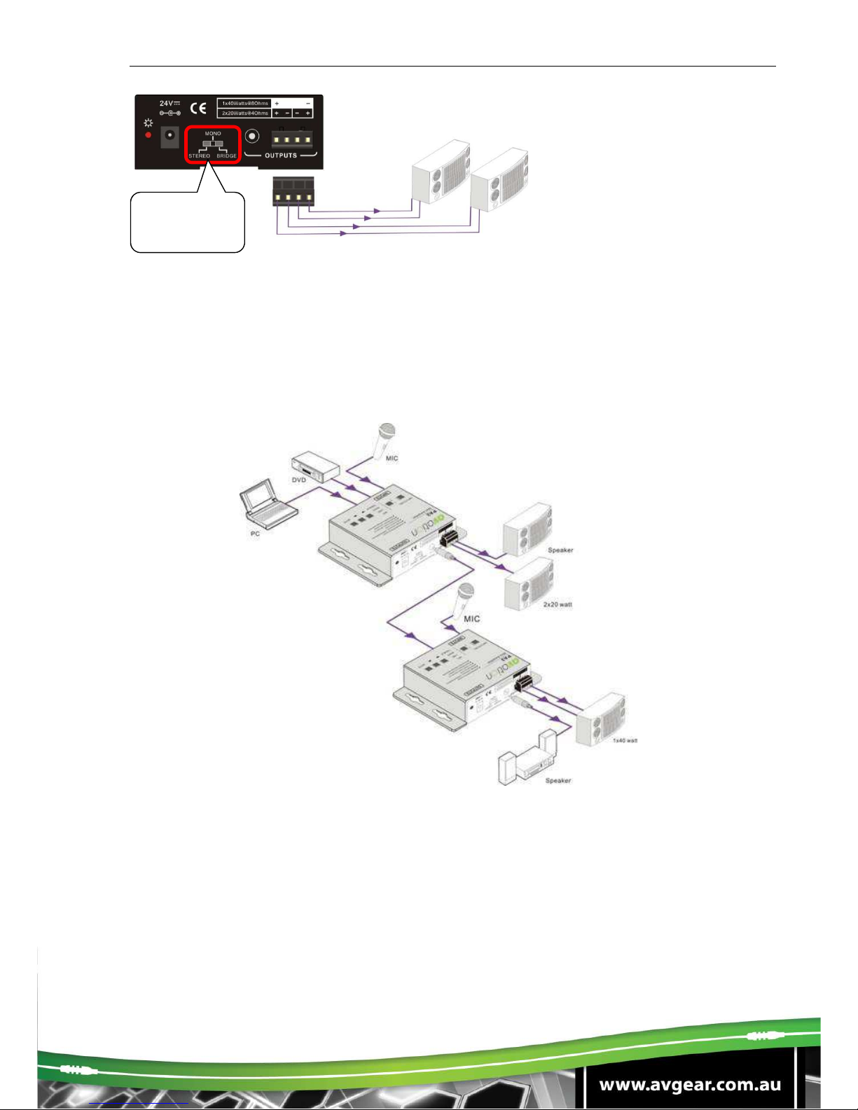
AVG-MA1
3.4 System Diagram
Switching to the
“MONO”
Connecting the four pins, like this
2x20Watt@4Ohm
Looping connection
1x40Watt@8Ohm

AVG-MA1
4. Operating the MA1
The buttons provides control of volume/EQ and switching.
4.1 Audio switching:
There are two switchable stereo audio inputs, Input 1- 2xRCA LR connectors and Input 2-
3.5mm jack that can be selected as the Line source for the MA1. This is switched using the
Input Select button as below:
4.2 Volume/EQ control:
The line volume and Microphone volume can be controlled by the buttons allowing the user
to create a mixed Audio Output.
The Mic Volume/Line volume/Line bass/Line treble is first selected by the left function select
button. Up/Down/Mute is then possible by pressing the right hand function buttons. Please
refer to the picture below:
For example, to turn up the line volume, you should select the “LINE” first, and then press
the up button “ ”.
Select the function from
this menu in advance Turn up/down the level. Or
mute the line volume
Source
Selection
AVG-MA1
4.3 RS232 Communication Protocol:
Baud rate: 9600 Data bit: 8 Stop bit: 1 Parity bit: none
Command
Function Description Feedback Code
1A1. Switching the audio to
input 1 A: 1 -> 1
2A1. Switching the audio to
input 2 A: 2 -> 1
0A0. Mute Audio of MIC and
Line out Mute Audio
1A0. Mute audio of MIC Mute MIC
2A0. Mute audio of line out Mute LIN
0A1. Un-Mute Audio Unmute Audio
600% Checking the working
status
A: 1 -> 1
Volume :30
Bass 00
Treble 00
601% MIC volume up Volume of MIC :
51
602% MIC volume down Volume of MIC :
51
603% Line volume up Volume of LINE :
51
604% Line volume down Volume of LINE :
51
605% Bass level up Bass of LINE :
04
606% Bass level down Bass of LINE :
04
607% Treble level up Treble of LINE :
04
608% Treble level down Treble of LINE :
04

AVG-MA1
609% Initialization, back to the
default setting
A: 1 -> 1
Volume :50
Bass 07
Treble 07
Command
Function Description
Feedback Code
5[x][x]% Preset MIC volume, [xx] is
ranging from [00] to [60].
61 increments in total.
Volume of MIC
:50
7[x][x]% Preset line volume, [xx] is
ranging from [00] to [60].
61 increments in total.
Volume of LINE
:50
8[x][x]% Preset the bass level, [xx]
is ranging from [00] to
[08].
9 increments in total.
Bass of LINE :
04
9[x][x]% Preset the treble level,
[xx] is ranging from [00] to
[08].
9 increments in total.
Treble of LINE :
04
Notice:
1: The letter inside the bracket [ ] is the variable code, which is the variable.
2: The bracket [ ] is not included into the RS232 commands.
Example 1
Switching input 2 to the line out. We should send the RS232 command: [2A1.]
Example 2
Turning up the volume of line audio. We should send the RS232 command: [603%]
Example 3
To Preset the MIC volume to be “21”, we should send the RS232 command: [521%]
Example 4
Checking the working status of MA1. We should send the RS232 command: [600%]

AVG-MA1
5.Specifications
Audio Input Audio Output
Input
2 stereo
audio,
1 MIC
Output 1 Amplifier,
1 stereo audio
Input
Connector
2 RCA
1 3.5mm jack
1 6.5mm jack
Output
Connector
1 3.5mm jack
1 Captive screw
connector, 4 pole
Input
Impedance
>10KΩOutput
Impedance 50Ω/stereo,
4~8Ω/Amplifier
Audio General
Frequency
Response 20Hz ~
20KHz CMRR >70dB@20Hz~20KHz
SNR 80dB at
maximum
output Bandwidth 20Hz ~ 25KHz
Stereo
Channel
Separation
>75dB@20Hz
to 20KHz THD + Noise 1%@1KHz,
0.3%@20KHz at
nominal level
Voltage
Gain 32dB Power Output 20 Watts X 2 (4
Ohms)
Control Parts
Serial
Control
Port
RS-232, 9-pin
female D
connector
Pin
Configurations
2 = TX, 3 = RX, 5 =
GND
IR Remote
Optional IR
remote Front Panel
Control Optional mountable
keypad
Options TCP/IP control by PTNET(PTN's programmable
interface)
NOTE: All nominal levels are at ±10%.
Table of contents
Popular Music Equipment manuals by other brands


K&K Sound
K&K Sound Bass Master Rockabilly quick start guide

Soundstream
Soundstream Large Mouth Bass Control installation instructions

BYOC
BYOC Classic Compressor Kit instructions

auray
auray RF-CPB-18 owner's manual

PRESONUS
PRESONUS VXP - Technical specifications

Lithium Grim
Lithium Grim Klon-ed Buffer Building instructions