2
electronics and shortens the input to the output XLR's. The power
indicator light will dim a bit to show that the unit is bypassed.
If you wish to use the unit for straight line gain, but with
bypassed equalisation, all eq is fully turned off when the mode
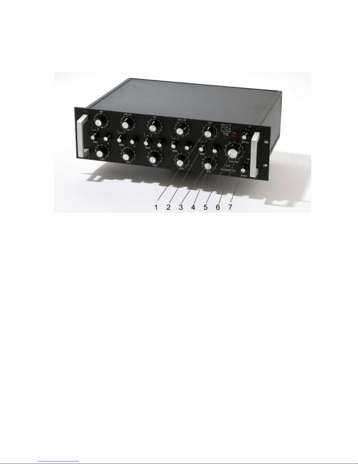
select switches (2) are in their centre position.
The G14 consists of five bands with selectable frequencies, “Q”,
and boost/cut. Frequency is selected by the upper row of switches
(1), and boost, bypass, or cut is selected for each individual
band by the mode switch (2). The sharpness, ”Q”, of each filter is
selected by the Q-knob (4) – “sharp” or “high Q” is at the
clockwise direction. The “Level” control (3) controls the amount
of applied boost or cut – depending on what function is selected
by the mode switch.
The Output trim pot (5) controls the signal level from the filters
to the output driver stage and the output. There is some 6dB of
spare gain obtainable – unity gain is around 1 O’clock at the
output trim pot. The output impedance of this unit is around 1K
Ohm, and is - like the input - floating transformer balanced.
Note that the way we implement the passive filtering has a couple
of side effects that should be considered in use:
First of all, the range of maximum boost and cut is limited to
some 10-12dB at each band – depending on “Q” setting.
Second, there is no “adding up” of adjacent bands – if you boost
two bands at the same (or close) frequency, you won’t end up with
double the boost/cut range. This is true for all passive equalizer
topologies.
Third, because of the parallel-passive architecture, the maximum
available “Q” is higher at the upper frequencies of each band than
at the lower frequencies of the band, and is sharper in cut mode
than in boost mode. This distribution of filter bandwidth gives a
very intuitive control of the equalizer, but also somewhat limits
the maximum available sharpness of the individual filters.