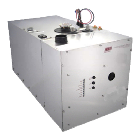
AVIAIR AVI35 User manual

Installation and User Manual

2

3
Designed and assembled in Canada by Distribution Avi-Air Inc.
Modèle : AVI35W
Intake Ventilator : 1-60Hz 240V 1,9A RPM 3255
CSA 172512
Exhaust Ventilator : 1-60Hz 240V 1,9A RPM 3255
CSA 172512
Patent Pending USPTO 62/366,657
www.distributionavi-air.com
114 Rang Roy 450 375 5539
Saint-Alphonse de Granby 450 531 9865
J0E2A0 sales@distributionavi-air.com
Qc, Canada

4
Table of content
Electrician’s note and diagram……………………………….………..…Page 5
Installation Guide…………………………………………….……….…….Page 17
Warranty………………………………………………….…….….…...…….Page 21

5
Electrician's Notes
and Connection
Diagram
The manufacturer recommends that the electrical
connection be performed by a qualified electrician.

6
Warnings and precautions
Recovery probe
Only one probe per stage is used per regulator. The probe is assigned to the INTAKE
ventilator of the recuperator.
The INTAKE fan will be activated based on this probe when the Avi35 is in recovery mode.
If more than one recuperator is connected in series to the regulator, the manufacturer
recommends to place the probe on the Avi35 recuperator which will be used during the
departure of a flock, or the one which will work in the first place.
The manufacturer recommends installing the probe at one end of the INTAKE fan leg support.
The probe should be secured at a minimum distance of 8 cm from the motor.

7
Warnings and precautions
DPDT relay used for defrost cycles in
Maximus
and AVI-28
The controller switch corresponding to the relay energizing the DPDT contactors (not included)
is automatically deactivated to prevent human error. Automatic deactivation of the switch
prevents undesired fan rotation inversions caused by the user.
DPDT contactors are energized only automatically by the controller.
Automatic Reversal of INTAKE Fan Rotation will not occur if the variable board switch
associated with the INTAKE fans is not set to automatic position.
The manufacturer recommends to check the reversal of rotation functions of the INTAKE fan at
the first start of the Avi35.
INTERLOCK double relays used for defrost cycles in
Multi-Zone
Genius
The GENIUS controller will used two relays to energize the corresponding interlock double
relay contactors (not included) that activates the defrost cycles. Therefore, the first relay will
activate the fan clockwise, whereas the second relay will activate the fan counterclock wise.
The manufacturer recommends to check the reversal of rotation functions of the INTAKE fan at
the first start of the Avi35.

8
Warnings and precautions
Automated rinsing system
The manufacturer recommends the use of a centrifugal booster pump (not included) providing
a minimum of 10 gpm at 50 psi to provide sufficient water to the flushing system.
All regulators in the same building use the same centrifugal booster pump.
Each solenoid valve 240V must be connected to a single ON / OFF relay of the regulator.
Each valve has its own circuit.
MULTIFAN MOTOR SPECIFICATION

9
Warnings and precautions
INTAKE AND
EXHAUST VENTILATORS
The manufacturer recommends consulting the regulator installation guide for connection to the
variable board and the ON / OFF relays.
The manufacturer recommends a maximum of six Avi35 pickups by Gev2 accessory card
amplifier for Genius Itouch.
The manufacturer recommends a maximum of three Avi 35 per variable relay card from a
Genius Itouch controller.
The manufacturer recommends a maximum of five Avi35 per variable relay card from a
MAXIMUS controller.
EXHAUST VENTILATORS must be connected in parallel to a variable relay of the regulator.
Drill the plastic on the side of the shutter to pass the wire. Drill diagonally to reach the plastic
piece that supports the EXHAUST VENTILATOR. Keep enough space to allow the louves to
open without touching the electrical wire. See diagram.
The INTAKE VENTILATORS must be connected in parallel to another variable relay of the
regulator. Drill the upper right corner of the inlet fan housing to pass the wire and probe wire.
The manufacturer recommends using the same common L2 for the 230V solenoid valve of the
wash system, as well as the relay contactors and the AVi35 INTAKE and EXHAUST
VENTILATORS.
The manufacturer recommends installing a bipolar mechanical switch to each fan.
The manufacturer recommends a 3-wire cable to connect the EXHAUST VENTILATOR motor
to the bipolar mechanical switch associated with the EXHAUST VENTILATOR.
The manufacturer recommends a 6-wire cable to connect the INTAKE VENTILATOR motor to
the DPDT relay or the INTERLOCK relays and the bipolar mechanical switch associated with
the INTAKE VENTILATOR.
The manufacturer recommends a 3-wire cable to connect the solenoid valve.
The gauge of the wires must respect the electrical code in force in your area.

10
INSTALLATION AND ELECTRICLAL DIAGRAM

11
INSTALLATION AND ELECTRICLAL DIAGRAM

12
Maximus &AVI-28
CONNECTION DIAGRAM

13
GENIUS MULTI-ZONE
AVI35 CONNECTION DIAGRAM
With a pair of 3 poles interlock contactors and 1 NC

14
EXHAUST FAN CONNECTION DIAGRAM

15
INTAKE FAN CONNECTION DIAGRAM

16
Installation Guide

17
Warnings and precautions
The manufacturer recommends installing the recuperators in the wall of the building. Ideally,
the Avi35 should not be installed directly above each other to prevent ice build-up above the
unit on the lower floor. Also, plan for a large accumulation of ground ice at the exit of the
recuperator during winter.
The manufacturer also recommends that a distance of at least 7 meters be maintained
between the Avi35 recuperator and another standard building exhaust fan. The aim is to
prevent a return of stale and dusty air from other standard exhaust fans in the Avi35 fresh air
INTAKEs.
Do not drill holes in the bottom of the Avi35. See installation diagram 1
Secure the unit to the wall by aiming through the pre-drilled holes in the facade. Screw both
sides of the unit into the wall frame. See installation diagram 3.
Refer to diagram 4 regarding the drain plugs on Multifan fan motors

18
Installation diagram 1

19
Installation Diagram 4

20
Limited warranty
The assembled product and individual components are subject to rigorous inspection and
verification to ensure maximum product reliability and quality. However, the possibility of
breakage and / or malfunction may exist. Contact your supplier for service. The warranty is for
a period of three years from the date of sale. Proof of purchase is required to validate the
warranty.
In any case, the warranty applies only to manufacturing defects and specifically excludes any
damage caused by overload, short circuit, misuse, vandalism, unforeseen event, deluge, fire,
hail or natural disaster. Any modification and repair not authorized by the manufacturer on this
product automatically void the warranty and relieves the manufacturer of any liability.
The manufacturer assumes only the aforementioned obligations, excluding any other
warranties or obligations. This warranty states that in all cases the manufacturer will be
responsible only for the replacement of defective parts and will not be liable for any personal
injury, damage, loss of profit, stoppage of operations, fines for contravention of the law or
damage to the production of BUYER. The BUYER takes over the defense and holds the
innocent manufacturer in any of the legal or extralegal procedures or request of the customer
or by a third party and in respect of any legal or extralegal expenses and fees occasioned by
such damage.
Table of contents
Popular Heating System manuals by other brands
Shop-Vac
Shop-Vac Blower Series Assembly instructions

2VV
2VV DAPHNE Installation

Viessmann
Viessmann VITODENS operating instructions
Napoleon
Napoleon DYNAMIC HEAT CONTROL PLUS Series Installation and operation manual

ProFusion
ProFusion GD8115BP-L owner's manual

Glowworm
Glowworm HYBRID COMPACT System installation

Nibe
Nibe F370 Quick start user guide

Caladair
Caladair Freetime Series Operating and Commissioning Instructions

HDG
HDG Compact 25 operating manual

Lifebreath
Lifebreath METRO 120D installation manual

Sunquest
Sunquest SQ-2212 Installation & operation manual

Viessmann
Viessmann VITOVENT 300 Service instructions