wagner solar CIRCOtransfer 30 E User manual

2015/03 EN-XXX_CIRCOtransfer-30E-50E_TI-MA-BA-150401-3PAW0501 - 99609x7WAG0x-mub-en - V06 1
Installation and Operation Instructions
Transfer stations:
CIRCOtransfer 30 E
CIRCOtransfer 50 E
[Hydraulics]
CIRCOtransfer 30 E
CIRCOtransfer 50 E

1 General information
2 EN-XXX_CIRCOtransfer-30E-50E_TI-MA-BA-150401-3PAW0501 - 99609x7WAG0x-mub-en - V06 2015/03
EN-XXX_CIRCOtransfer-30E-50E_TI-MA-BA-150401-3PAW0501
Item no. 99609x7WAG0x-mub-en –Version V06 –Issued 2015/03
Translation of the original instructions
We reserve the right to make technical changes without notice!
Printed in Germany –Copyright by Wagner Solar GmbH
Wagner Solar GmbH
Industriestraße 10
D-35091 Cölbe, Germany

1 General information
2015/03 EN-XXX_CIRCOtransfer-30E-50E_TI-MA-BA-150401-3PAW0501 - 99609x7WAG0x-mub-en - V06 3
Contents
1General information ...........................................................................................................4
1.1 About these instructions ............................................................................................... 4
1.2 About this product ........................................................................................................ 5
1.3 Designated use ............................................................................................................ 6
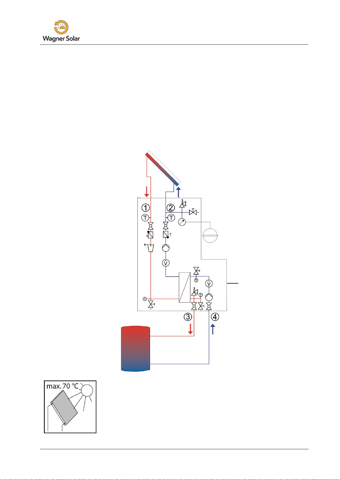
2Safety instructions .............................................................................................................7
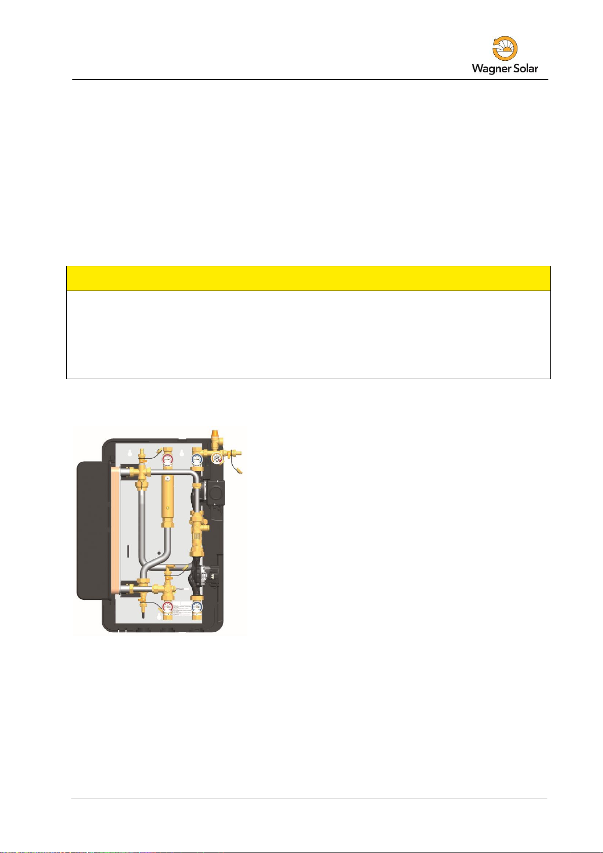
3Assembly and installation [specialist] ..................................................................................9
3.1 Controller connection ................................................................................................. 11
4Commissioning [specialist] ...............................................................................................12
4.1 Preparations before flushing and filling....................................................................... 13
4.2 Flushing and filling the storage tank circuit................................................................. 13
4.3 Flushing and filling the solar circuit............................................................................. 14
4.4 Maintenance [specialist] ............................................................................................. 19
4.5 Draining the solar installation ..................................................................................... 20
4.6 Deinstallation.............................................................................................................. 20
5Spare parts [specialist].....................................................................................................21
5.1Spare parts primary circuit CIRCOtransfer 30 E (15020220)...................................... 21
5.2 Spare parts secondary circuit CIRCOtransfer 30 E (15020220) ................................. 22
5.3 Spare parts primary circuit CIRCOtransfer 50 E (15020221)...................................... 23
5.4 Spare parts secondary circuit CIRCOtransfer 50 E (15020221) ................................. 24
6Technical data .................................................................................................................25
6.1 Dimensional drawing CIRCOtransfer 30 E ................................................................. 26
6.2 Dimensional drawing CIRCOtransfer 50 E ................................................................. 27
6.3 Pressure drop characteristics CIRCOtransfer 30 E .................................................... 28
6.4 Pressure drop characteristics CIRCOtransfer 50 E .................................................... 28
7Function of the check valves [specialist]............................................................................29
8Commissioning report ......................................................................................................31

1 General information
4 EN-XXX_CIRCOtransfer-30E-50E_TI-MA-BA-150401-3PAW0501 - 99609x7WAG0x-mub-en - V06 2015/03
1General information
Carefully read these instructions before installation and commissioning.
Save these instructions in the vicinity of the installation for future reference.
1.1 About these instructions
These instructions describe the function, installation, commissioning and operation of the
transfer stations CIRCOtransfer 30 E and CIRCOtransfer 50 E.
The chapters called [specialist] are intended for specialists only. For other components of the
installation, such as pumps, controllers or the distribution manifold, see the manufacturers'
instructions.
CIRCOtransfer 30 E –item number 150 202 20
Power [kW]
Collector surface [m²]
Low-flow [17 l/m²h]
30
50
High-flow [35 l/m²h]
16
26
CIRCOtransfer 50 E –item number 150 202 21
Power [kW]
Collector surface [m²]
Low-Flow [17 l/m²h]
54
90
High-Flow [35 l/m²h]
30
50

1 General information
2015/03 EN-XXX_CIRCOtransfer-30E-50E_TI-MA-BA-150401-3PAW0501 - 99609x7WAG0x-mub-en - V06 5
1.2 About this product
The station is a premounted group of fittings checked for leakage and used to transfer the heat
from the primary or solar circuit to the secondary or storage tank circuit.
It contains important fittings and safety devices for the operation of the installation:
Ball valves with integrated thermometers in the storage tank circuit
(flow and return)
Check valves to avoid involuntary gravity circulation in the flow and return of the primary
and the secondary circuit.
Pressure relief valves to prevent inadmissible overpressures
Pressure gauge to display the system pressure in the solar circuit
Vent valves to easily vent the solar circuit
Fill and drain valves to flush, fill and drain the solar circuit
Two flow meters and electronic temperature sensors for heat quantity balancing
(secondary) and speed control of the pumps depending on the performance
The expansion tank required for operation must be adapted to the size and the requirements of
the installation and must be ordered separately.
The cap-type valve, which is also separately available, allows the expansion tank to be easily
mounted and separated from the solar thermal system.
The wrapping materials are made of recyclable materials and can be disposed of with
recyclable materials.

1 General information
6 EN-XXX_CIRCOtransfer-30E-50E_TI-MA-BA-150401-3PAW0501 - 99609x7WAG0x-mub-en - V06 2015/03
1.3 Designated use
The station may only be used as a transfer station between the solar and the heating circuit in
solar thermal systems taking into consideration the technical limit values indicated in these
instructions. Due to its design the station must be mounted and operated as described in these
instructions!
Only use original accessories with the transfer station.
Improper usage excludes any liability claims.
When the sun shines, the collectors can become very hot.
The solar fluid in the circuit can heat up to more than 100 °C.
Only flush and fill the solar circuit when the collector temperatures are
below 70 °C.
Schematic structure
CIRCOtransfer 30 E/50 E
Scope of
delivery

2 Safety instructions
2015/03 EN-XXX_CIRCOtransfer-30E-50E_TI-MA-BA-150401-3PAW0501 - 99609x7WAG0x-mub-en - V06 7
2Safety instructions
The installation and commissioning as well as the connection of electrical components require
technical knowledge commensurate with a recognised vocational qualification as a fitter for
plumbing, heating and air conditioning technology, or a profession requiring a comparable level
of knowledge [specialist].
The following must be observed during installation and commissioning:
relevant local and national regulations
accident prevention regulations of the professional association
instructions and safety instructions mentioned in this manual
WARNING
Danger of scalding due to vapour escape!
With pressure relief valves there is risk of scalding due to vapour escape.
During installation, check the local conditions and if a discharge line must be
connected to the safety group.
Observe the instructions regarding the pressure relief valve.
The pressures calculated by the installation planner for the expansion tank
and the operating pressure of the installation must be set.
CAUTION
Risk of burns!
The valves, fittings and the pump may heat up to more than 100 °C during
operation.
The shell must remain closed during operation.

2 Safety instructions
8 EN-XXX_CIRCOtransfer-30E-50E_TI-MA-BA-150401-3PAW0501 - 99609x7WAG0x-mub-en - V06 2015/03
CAUTION
Personal injury and damage to property due to overpressure!
By closing the two ball valves in the primary circuit you isolate the pressure relief
valve from the heat exchanger. A rise in temperature in the storage tank will
cause high pressures and could result in personal injury or damage to property!
Only close the ball valves for service and maintenance.
NOTICE
Material damage due to mineral oils!
Mineral oil products cause lasting damage to seals made of EPDM, whereby the sealant
properties get lost. We do not assume liability nor provide warranty for damage to property
resulting from sealants damaged in this way.
It is imperative to avoid that EPDM gets in contact with substances containing
mineral oils.
Use a lubricant based on silicone or polyalkylene and free of mineral oils, such as
Unisilikon L250L and Syntheso Glep 1 of the Klüber company or a silicone spray.

3 Assembly and installation [specialist]
2015/03 EN-XXX_CIRCOtransfer-30E-50E_TI-MA-BA-150401-3PAW0501 - 99609x7WAG0x-mub-en - V06 9
3Assembly and installation [specialist]
The location of installation must be dry, load-carrying, frost-proof and protected against
ultraviolet radiation. Furthermore, the access to the control and safety equipment must be
guaranteed at all time during operation!
The discharge line of the safety equipment should be guided into a heat-resistant container with
corresponding size. This allows you to avoid uncontrolled discharging into the environment and
to easily refill the circuits!
NOTICE
Material damage due to high temperatures!
Install the fitting group at a sufficient distance from the collector field, since the solar fluid may
be very hot near the collector.
It may be necessary to install an intermediate tank in order to protect the expansion tank.
1. You can use a drilling template in order to facilitate the
installation, which you can find on the station.
2. Copy the mounting hole measures to the mounting
surface.
3. Drill the holes and insert apropriate wall plugs into the
holes.
4. Screw in the screws and let them stick about 4 cm out
of the wall.
5. Remove the station from the packaging.
6. Remove the insulating front shell.
Hang the station onto the screws and tighten
the screws.

3 Assembly and installation [specialist]
10 EN-XXX_CIRCOtransfer-30E-50E_TI-MA-BA-150401-3PAW0501 - 99609x7WAG0x-mub-en - V06 2015/03
7. Connect the transfer station to the system:
①Solar flow from the collector
②Solar return to the collector
③Flow to the buffer tank
④Return from the buffer tank
All screw connections of the CIRCOtransfer 30 E have
¾" internal threads, all screw connections of the
CIRCOtransfer 50 E have 1" internal threads.
8. Mount the safety group, consisting of the pressure
relief valve [c], the fill valve [d] and the pressure
gauge [e], to the connection of the return ball valve [b].
9. Connect the expansion tank below the pressure
gauge [e]. During servicing at the expansion tank, we
recommend the installation of a cap valve on the
expansion tank.
NOTICE
Note regarding the expansion tank
The expansion tank must not be connected while flushing and filling in order to avoid that dirt
particles are washed in.
10. Pressurise the expansion tank as specified by the
manufacturer and connect the expansion tank.
Observe the separate instructions regarding the
expansion tank!
11. Check all screw connections and tighten them
if necessary.

3 Assembly and installation [specialist]
2015/03 EN-XXX_CIRCOtransfer-30E-50E_TI-MA-BA-150401-3PAW0501 - 99609x7WAG0x-mub-en - V06 11
3.1 Controller connection
Connect the optional controller to the mains. You can find a detailed description for the
operation of the controller in the separate controller manual.
WARNING
Risk to life and limb due to electric shock!
Prior to commencing electrical work on the controller, pull the mains plug!
Only after completing all installation work, flushing and filling, plug the
mains plug of the controller into a socket.
Thus, an unintentional start of the motors is avoided.

4 Commissioning [specialist]
12 EN-XXX_CIRCOtransfer-30E-50E_TI-MA-BA-150401-3PAW0501 - 99609x7WAG0x-mub-en - V06 2015/03
4Commissioning [specialist]
Observe the following safety instructions regarding the commissioning of the station:
WARNING
Risk of burning and scalding!
The fittings can heat up to more than 100 °C. Therefore, do not clean or fill the
system with the collectors heated (intense sunshine). Please note that hot solar
fluid can leak from the pressure relief valve when the system pressure is too high!
During venting the solar fluid may escape as vapour and cause scalding!
Only flush and fill the solar circuit when the collector temperatures
are below 70 °C.
CAUTION
Risk of frost!
It often happens that the solar thermal system cannot be completely drained after flushing.
Thus, there is risk of frost damage when flushing with water. Therefore, do only use the solar
fluid used later to flush and fill the solar installation.
Use a water and propylene glycol mixture with max. 50% of propylene glycol as
solar fluid.
CAUTION
Note regarding the commissioning sequence
Flush and fill in the following order:
1. Flush the storage tank (to remove scale residues).
2. Fill the storage tank circuit.
3. Vent the heat exchanger by means of the pressure relief valve.
4. Flush and fill the solar circuit of the heat exchanger.
5. Flush and fill the collector field.
6. Flush and fill the entire solar circuit.
This guarantees that the dirt particles are not flushed into the heat exchanger and that
eventually absorbed heat can be dissipated.

4 Commissioning [specialist]
2015/03 EN-XXX_CIRCOtransfer-30E-50E_TI-MA-BA-150401-3PAW0501 - 99609x7WAG0x-mub-en - V06 13
4.1 Preparations before flushing and filling
CAUTION
Note regarding the expansion tank
To prevent that the dirt particles in the solar thermal system are flushed into the expansion
tank, some manufacturers recommend to disconnect the expansion tank from the solar circuit
before flushing and filling. Please observe the instructions of the manufacturer.
4.2 Flushing and filling the storage tank circuit
The storage tank circuit is filled by means of the valves and fittings of the heating system.
To avoid that dirt particles are washed into the heat exchanger, close the ball valves of the station
and wash out the present dirt particles and scale residues before commissioning the tank.
Make sure to only use purified heating water according to VDI 2035 / Ö-Norm H 5195 1.
1. Open the ball valves [D|E] and put the check
valves out of operation (45°, see next page).
2. Vent the storage tank circuit by operating the
vent plug [A] on the cross.
Make sure that the electrical components do not
get wet.
3. Fill heating water into the storage tank circuit by
means of the fill and drain valve.
4. Set the required operating pressure after filling
the storage tank circuit.
5. During commissioning, vent the station at the
vent plug [A] in order to eliminate air still present
in the heat exchanger.
Storage tank circuit

4 Commissioning [specialist]
14 EN-XXX_CIRCOtransfer-30E-50E_TI-MA-BA-150401-3PAW0501 - 99609x7WAG0x-mub-en - V06 2015/03
4.3 Flushing and filling the solar circuit
The fill and drain valves required to flush and fill are integrated in the transfer station. Make sure
not to wash dirt particles that may be present in the system into the heat exchanger and the
expansion tank. Disconnect the expansion tank from the solar circuit during flushing and filling,
if necessary, and only use flush and fill stations with fine filters.
The solar circuit is flushed in the direction of flow. Make sure that the pump in the solar circuit
cannot be switched on.
Ball valve with integrated flow check valve
(normal flow direction in the figure below: downwards)
0°
45°
90°
Check valve is operating,
flow only in flow direction.
Check valve is not operating,
flow in both directions.
Ball valve closed,
no flow.

4 Commissioning [specialist]
2015/03 EN-XXX_CIRCOtransfer-30E-50E_TI-MA-BA-150401-3PAW0501 - 99609x7WAG0x-mub-en - V06 15
Airstop
The Airstop (air-scoop with plug for manual venting) serves to
bleed the solar installation. To ensure perfect deaeration of the
solar circuit, the flow velocity must be at least 0.3 m/s in the
flow line.
Pipe diameter [mm]
Flow rate at 0.3 m/s
∅outside
∅ inside
l/h
l/min
15
13
~ 143
~ 2.4
18
16
~ 217
~ 3.6
22
20
~ 339
~ 5.7
28
25
~ 530
~ 8.8
The air separated from the solar fluid is collected in the upper part of the Airstop and can be
released at the vent plug [j].
WARNING
Danger of scalding due to vapour escape!
The escaping fluid can have a temperature of more than 100 °C and cause
scalding.
Carefully open the vent plug and close it again, as soon as medium
escapes.
Venting the solar installation after commissioning
At the beginning, vent the solar installation daily and then weekly or monthly,
depending on the vented air quantity. Thus, an optimum operation of the solar
installation is ensured. Check the system pressure after venting and increase it to
the specified operating pressure, if necessary.
j

4 Commissioning [specialist]
16 EN-XXX_CIRCOtransfer-30E-50E_TI-MA-BA-150401-3PAW0501 - 99609x7WAG0x-mub-en - V06 2015/03
1. Disconnect the expansion tank from the solar
installation. This avoids the access of dirt
particles present in the pipes to the expansion
tank. Observe the separate instructions
regarding the expansion tank!
2. The return ball valve [b] must be closed
(90° position, see page 14).
3. Connect the flush and fill station:
- Pressure hose to the fill valve [d]
- Flush hose to the drain valve [h].
4. Open the fill and drain valves [d|h] and put the
flush and fill station into operation.
5. Slowly open and close the return ball valve [b]
and the drain valve [k] during flushing in order
to vent the pump section.
6. Flush the solar circuit until the solar fluid exits
without bubbles (see page 15).
7. Close the drain valve [h] with the filling pump
running and increase the system pressure to
about 5 bars. The system pressure can be read
on the pressure gauge [e].
8. Close the fill valve [d] and switch off the pump
of the flush and fill station.
9. Check the pressure gauge to see whether the
system pressure reduces and eliminate leaks
where necessary.
Observe the pressure (max. 6 bars)!
Solar circuit

4 Commissioning [specialist]
2015/03 EN-XXX_CIRCOtransfer-30E-50E_TI-MA-BA-150401-3PAW0501 - 99609x7WAG0x-mub-en - V06 17
10. Reduce the pressure at the drain valve [h] to
the operating pressure, if necessary.
11. Connect the expansion tank to the solar circuit
and set the operating pressure of the solar
thermal system by means of the flush and fill
station (for the required operating pressure,
see the instructions of the expansion tank).
12. Close the fill and drain valves [d|h].
13. Put the ball valve [b] into 0° position
(see page 14).
WARNING
Risk to life and limb due to electric shock!
Check if the sensors and the pumps are properly connected to the
controller and if the controller housing is closed.
Only then should the mains plug of the controller be plugged into a socket.
14. Connect the optional controller to the mains and
set the solar circuit pump to ON in the manual
mode according to the controller instructions.
15. Let the solar pump run at maximum rotation
speed for at least 15 minutes.
Meanwhile vent the solar installation several times
at the vent plug [j] of the Airstop until the solar
fluid exits without bubbles (see page 15).
16. If necessary, increase the system pressure to the
operating pressure.

4 Commissioning [specialist]
18 EN-XXX_CIRCOtransfer-30E-50E_TI-MA-BA-150401-3PAW0501 - 99609x7WAG0x-mub-en - V06 2015/03
17. Remove the hoses of the flush and fill station and
screw the sealing caps onto the fill and drain
valves. The sealing caps only serve to protect the
valves against dirt. They are not designed to take
up high system pressures. The ball valves must
be closed.
18. Mount the insulating front shell.
19. Set to automatic mode on the controller
(see controller instructions).
The commissioning of the solar installation is now
completed.
Please fill in completely the commissioning report on
page 31.

4 Commissioning [specialist]
2015/03 EN-XXX_CIRCOtransfer-30E-50E_TI-MA-BA-150401-3PAW0501 - 99609x7WAG0x-mub-en - V06 19
4.4 Maintenance [specialist]
Make sure that the system is not under pressure during service and maintenance works at
the station.
WARNING
Risk of burning and scalding!
The valves, fittings and solar fluid can reach temperatures of more than 100 °C.
The solar fluid can escape as vapor and cause scalding.
Only carry out maintenance work when the collector temperatures are
below 50 °C.
Wait until the solar fluid has cooled down to max. 50 °C.
Example: CIRCOtransfer 30 E
1. Close the ball valves [a|b] and drain the solar
fluid at the drain valve [h].
Make sure that the solar fluid is collected in a heat-
resistant container.
2. Change the faulty part against the new part.
3. Fill the solar circuit as described in 4.3 Flushing and
filling the solar circuit (see page 14).

4 Commissioning [specialist]
20 EN-XXX_CIRCOtransfer-30E-50E_TI-MA-BA-150401-3PAW0501 - 99609x7WAG0x-mub-en - V06 2015/03
4.5 Draining the solar installation
1. Switch off the controller and make sure that a
restart is not possible.
2. Open the check valves in the flow and return ball
valve [a|b], by turning them to a 45° position
(see page 14).
3. Connect a heat-resistant hose to the drain
valve [h] of the transfer station.
Make sure that the solar fluid is collected in a
heat-resistant container.
WARNING
Danger of scalding due to hot solar fluid!
The escaping fluid may be very hot.
Place and fix the heat-resistant collecting container so that people
standing nearby are not endangered when the solar installation is
being emptied.
4. Open the drain valve [h] of the transfer station.
5. To accelerate draining of the solar circuit, you can open the bleeding device,
if present, at the highest point of the solar thermal system.
6. Dispose of the solar fluid observing the local regulations.
4.6 Deinstallation
1. Drain the solar thermal installation as described above.
2. Disconnect the pipe joints with the solar thermal system.
3. Disconnect the cable connections between controllers and sensors
(collector/ storage tank).
4. Loosen the fastening screws of the station and take the station off the wall.
This manual suits for next models
3
Table of contents
Popular Heating System manuals by other brands

Truma
Truma Trumatic E 2400 E Operating instructions and installation instructions

Viessmann
Viessmann Vitodens 100-W operating instructions

Bryant
Bryant 580G Installation, Start-Up and Service Instructions

Dimplex
Dimplex DWF1203 troubleshooting guide

Empire Comfort Systems
Empire Comfort Systems DV-822 installation instructions

Vent-Axia
Vent-Axia 448733 Installation & commissioning

Xvent
Xvent Xflat Quick user guide

Thermon
Thermon Terminator DE-B Installation procedures

Toyotomi
Toyotomi FF-V30 Operation instructions

Creda
Creda Advanced Control Heating Systems Specification sheet

MOOD
MOOD BLANCO Installation and operating instructions

Viessmann
Viessmann VITOBLOC 200 Technical description