4 / 36
TF6400_A Aereco S.A.
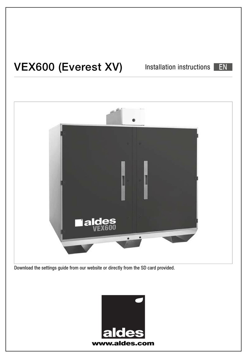
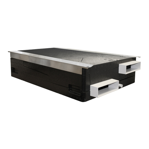
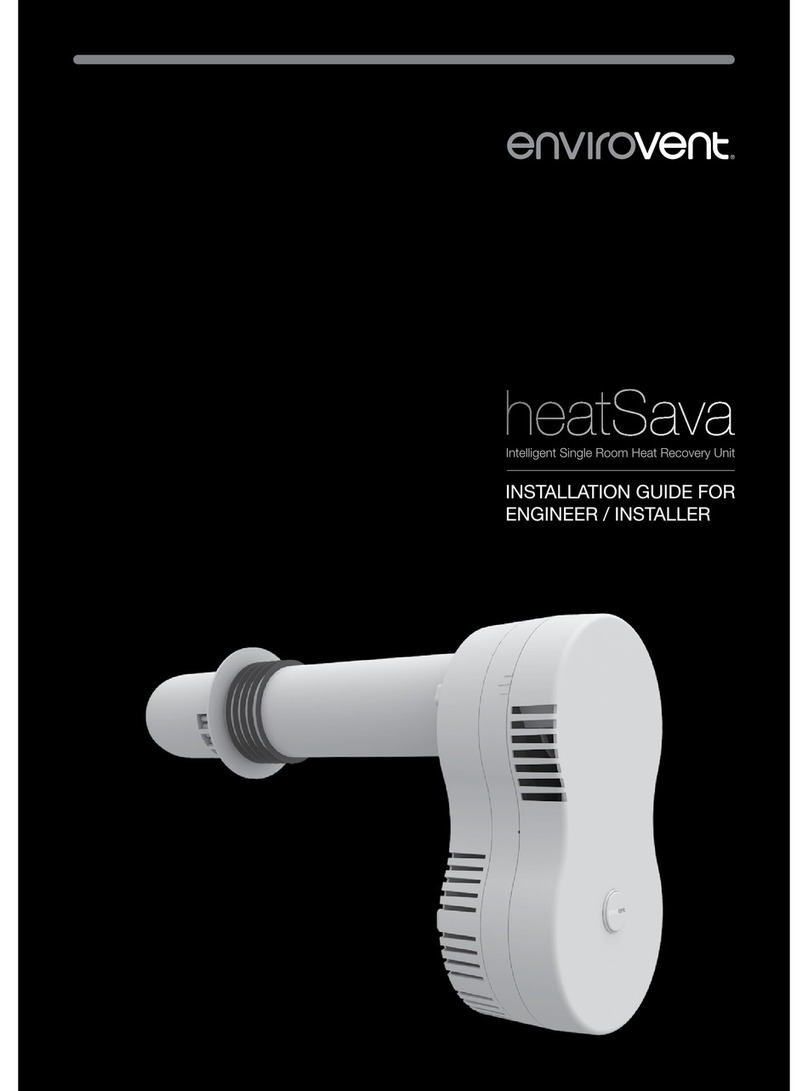
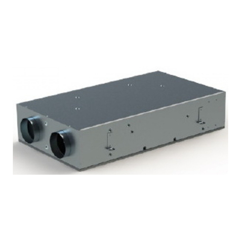
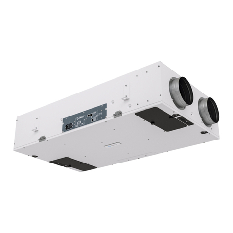
The Heat Recovery Unit : DXA Unit
The DXA has been specifically designed for
wall or cupboards installation. Thanks to
its wellfitted dimensions, the DXA can be
installed in technical rooms, wallmounted.
A creamy white metal sheet covers the front
face of the the DXA which allows it to be
unnoticed as a technical equipment. The DXA
unit is compatible with two demand control
strategies used in the DX System “Premium”
and “Excellence”.
2. DESCRIPTION
2.1. GENERAL INFORMATION
The DX System is a range of smart heat recovery ventilation systems that continually supply pollen-free and dust-free preheated fresh air to living areas,
ensuring a comfortable feel-good climate.
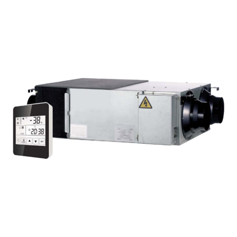
The DXA is a heat recovery unit with demand-controlled airflows for vertical installation (on the wall) in the apartment or in the house, from 2to 5 main
rooms, and from 1 to 5 technical rooms (kitchen, bathroom, others wet rooms). The dwelling has to be limited to 2 floors (1 ground floor and 1 floor
maximum), and has a maximum surface of 210m². This HRVsystem can also be used in oces, hostels, etc., if the required airflow is in accordance
with the one oered by the system.
General working of the DX System, Premium Version
The DXSystem is comprised of a heat recovery unit (DXA Unit 1 ) con-
nected to exhaust and supply ductworks. The counter-flow heat exchanger,
integrated into the main unit, ensures the recovery and transfer of most of
the energy from the exhaust air to the supply air, thus limiting the energy
required to heat the fresh air.
Airflows are automatically controlled according to the needs of each
dwelling’s room: a room by room DCV is ensured on the exhaust side while
on the supply side, airflow are managed globally by the mean of one or
several indoor air quality sensors 4. Preheated 8fresh air is supplied
3in the bedrooms and in the living room. Stale air is extracted 5from
the kitchen, bathroom and WC. To manage supply airflows, one or several
C02or presence sensors 4drive the exhaust compensation valve. If
several sensors are connected, a weighted average of the ventilation need
is calculated by the system to adap the airflow. With this strategy, the
exhaust airflow 5increase depending on the sensors measurement,
which will drive consequently the supply airflows. Supply airflows, as
they are distributed through a passive distribution box 2, are identical
in all the dierent main rooms (to the nearest drop pressure losses). On
the exhaust side, the exhaust units 5 adjust automatically the airflow,
according to parameters read by various sensors: humidity (used in the
kitchen, in the bathroom and in WC), presence (used in WC). Versions
with switch, presence, remote, CO2or VOC sensors can also be used for
exhaust units. In order to have a balanced system, supply airflows are
similar to exhaust airflows.
The use of an exhaust compensation valve 7 , connected to a specific
supply unit 6 , is also a solution to increase the airflows. This scenario
is used in order to get a very ecient over-ventilation mode, also called
free-cooling mode.
Supply airflows and exhaust airflows are measured by the use of accurate
pressure sensors placed in the heat recovery unit. This allows to calculate
with a high accuracy supply and exhaust airflows, without influence of
clogging filters or ductwork pressure drop. It ensures the highest eciency
for the system. So that, energy savings are at their maximum.
CO2 detection
Based on the level of CO2in the room, a
consequence of people occupancy, CO2
sensors are a really good indicators to
modulate the supply airflows, and allow reliable
measurement of the concentrations of CO2
in a zone. The analysis principle consists in
measuring the absorption of infrared light in
order to determine the concentration in a room.
This method gives a very accurate response
and is not aected by any other pollution
(humidity, dust, etc.).
Presence detection
The presence sensors located in the main rooms
(at least 1 sensor in one or several main rooms)
send the information to the system (presence
detected or not) with a timer that depends on
the period through luminosity measurement
(day or night). This timer keeps the detection
at the maximum level during 20 or 45 minutes
after the last detection, to optimize the quality
of detection. Timer day = 20 min ; Timer night
= 45 min. When there is detection, the local
supply airflow is increased to ensure the best
air quality. If there is no detection, the local
supply airflow is reduced to optimize energy
savings.


