manuals.online logo
Brands
  1. Home
  2. •
  3. Brands
  4. •
  5. Aviom
  6. •
  7. Computer Hardware
  8. •
  9. Aviom BOOM-1 User manual

Aviom BOOM-1 User manual

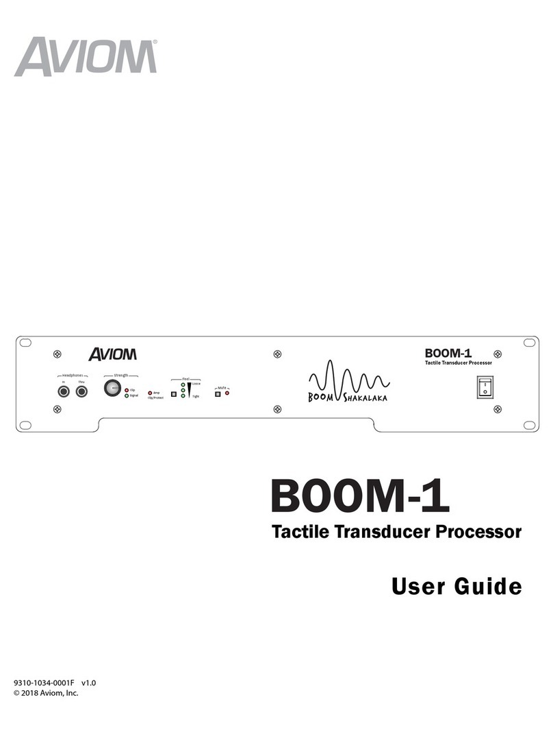
BOOM-1
Tactile Transducer Processor
Welcome to the BOOM team!
Thank you for purchasing the BOOM System. The
BOOM-1 Tactile Transducer Processor provides
optimized DSP and amplification for tactile
transducers that are mounted to drum thrones,
keyboard seats, platforms, performance stools, or
even installed in the floor of a stage.
This Quick Start Guide will help you set up and
optimize your BOOM System products to get the
best performance from your personal mixer, IEMs
or headphones, BOOM-1, and tactile transducer
products.
System Benets
Tactile transducers benet all in-ear and headphone
performers and are especially benecial to those using
electronic drum kits as well as guitar and bass amp
simulators. Why? Because playing an acoustic drum kit
or an electric guitar or bass through an amp actually
vibrates the performer’s physical surroundings and
this vibration becomes part of the live performance
experience and energy. When you switch to in-ears or
headphones and an electronic drum kit or a modeled
amp system without speaker cabinets, those natural
vibrations are lost…
Until now.
The BOOM System concept is simple: by adding a
natural feeling low-frequency tactile transducer
(also known as a“bass shaker”) to your drum throne,
keyboard seat, performance stool, performance
platform, or even to your stage oor, the body feels
bass frequencies, adding realism to the mix. The
benets extend to any performer who loses their on-
stage amplication to a silent stage.
Aviom has made it extremely easy to incorporate
tactile transducers into your monitor mixing system by
oering a suite of complementary products that are
designed to work together seamlessly. These include
the CTT-1 Clamp-On Tactile Transducer (powered by
ButtKicker®) for drum thrones and stools, the KBS-1
Keyboard Seat, PFS-1 Performance Stool, and the
ButtKicker-enhanced PLF-1 Platform.
How To Use The Boom System
Since the BOOM System makes virtually no audible
sound, it’s important to understand the concepts
behind its use to enable you to use it eectively in a
musical context. A little goes a long way.
Using a BOOM System device with your IEMs or
headphones should add back that amount of vibration
that previously came from the sympathetic vibrations
of the stage and its surroundings when acoustic drum
sets and/or ampliers were being used. You don’t
want the eect that’s used in a theme park or movie
sound system to shake everyone and everything
during a high-energy action sequence. You’re trying to
complete a musical picture, not rebalance or re-mix it.
We always suggest that you start with the tactile
system o (with the Strength knob at minimum) and
get a good stereo mix on your personal mixer rst at
a moderate listening level. Then, blend in the BOOM
System slowly while playing and/or singing. Set to a
musically useful level, the BOOM System will enhance
your monitoring experience and allow you to deliver a
performance with more energy and to do so at lower
overall monitoring levels.
And don’t forget, if you need more help, the complete
User Guide is available on the Aviom website.
Quick Start
1157 Phoenixville Pike, Suite 201 • West Chester, PA 19380 USA
Voice: +1 610.738.9005 • Fax: +1 610.738.9950 • www.Aviom.com
BOOM-1
Tactile Transducer Processor
In Thru
Tight
Loose
Amp
Clip/Protect
Signal
Clip
Feel
Mute
Headphones Strength
BOOM System Quick Start
Feature Description
1 AC power inlet 120-240VAC 50/60Hz, switching power supply, IEC connector
2 Fuse, size: 250VAC~ T3AL To check the fuse, remove the small cover below the AC inlet to open the fuse compartment.
3 Transducer Out Impedance 4-8 Ohms; locking speaker connector
4 Line-level output volume
control
Use this to control the amount of the BOOM-1 processed audio signal sent from the XLR Line Out to
an external amplier’s audio input.
5Balanced line-level output Connects the unit’s processed audio signal to an external amplier; XLR-M. Output is not aected by
the front panel Mute control.
6DSP Prole DIP switches See table.
7Balanced line-level input Connect mono, line-level audio from an A360 Personal Mixer, mixing console, etc.; XLR-F.
Any audio connected to the rear panel XLR Line In is sent directly to the internal DSP processor and
will not be heard in headphones (or earbuds) connected to either Headphone Thru jack.
8Headphone In and Thru Duplicate of the front-panel headphone I/O



  

Rear Panel Features
BOOM-1
Tactile Transducer Processor
In Thru
Tight
Loose
Amp
Clip/Protect
Signal
Clip
Feel
Mute
Headphones Strength

 
Feature Description
1 Stereo Headphone In and Thru The HEADPHONE IN1/4-inch jack on the BOOM-1 is designed to accept a left-right stereo, unbalanced
TRS audio signal from a personal mixer as its input. Connect your headphones or in-ears to THRU.
2 Strength Control with Signal
and Clip LEDs
The STRENGTH knob controls how much of the unit’s DSP-processed signal is sent to the tactile
transducer output and the rear-panel LINE OUT jack.
3 Amp Clip/Protect LED The AMP CLIP/PROTECT LED has these behaviors:
It will light red to indicate that the input to the amplier is overloading and causing distortion.
If that overload state persists and the amplier becomes overheated, the AMP CLIP/PROTECT LED will
begin to ash, indicating that the BOOM-1 has suspended operation to protect itself.
The AMP CLIP/PROTECT LED will also ash if the unit detects a short circuit on the transducer output
while there is a signicant audio output. In this case the LED will continue ashing for one second after
the circuit detects that the short circuit was removed.
4 Feel control with push button
selector and three LED
indicators
Loose – 3 LEDs – Highest compression threshold; allows more dynamic variations from soft to loud.
Medium – 2 LEDs – Average compression threshold; moderate lter cuto setting.
Tight – 1 LED – Lowest compression threshold; lowest low pass lter (LPF) setting .
5Mute control with push button
switch and LED
Temporarily silences the rear-panel transducer output while leaving the incoming source audio active
in the BOOM-1 headphone output. It’s great for auditioning with/without the BOOM System active.
The Mute control does not aect the Line Out.
Front Panel Features
BOOM System Quick Start
DSP Prole DIP Switches
The six DIP switches in the TRANSDUCER SYSTEM SELECT section of the
DSP Prole allow the response of the BOOM-1 output to be optimally
tuned to suit the specic type and model of tactile device that you
are using. The table below shows the switch settings for the Aviom-
branded products that include tactile transducers as well as settings
for some common bass shaker products that can be added to drum
thrones, platforms, or built into stage oors. Each combination
includes three unique Feel settings, chosen from the front panel.
The DIP switch block also includes settings for the high pass lter and
polarity. The default position for the high pass lter (HPF) is down.
This setting rolls o non-musical components (like rumble) sent to
the transducer output from 15Hz and below. When the switch is up,
the HPF cuto is moved higher, near 20 Hz. Use the eight DSP Prole DIP switches to match the
BOOM-1 to your tactile transducer.
The default Polarity position is set to match the mounting
orientation of the tactile transducer. You may want to try the
polarity set in the opposite direction; use the setting that provides
the best low-frequency feel for your application.
Remember, the DSP Prole setting for each transducer oers three
distinct Feel variations; be sure to try each and choose the one that
best suits your performance environment and playing style.
1 2 3 4 5 6 7 8
DIP SWITCH 12345678
PRODUCT:= DIP switch down
= DIP switch up
CTT-1 Clamp-On Transducer 
KBS-1 Keyboard Seat 
PFS-1 Performance Stool 
PLF-1 Platform 
CTT-1 Variation 1 
CTT-1 Variation 2 
Drum Throne with two Aura® shakers 
Drum Throne with two ADX® shakers 
Drum Throne with two BK mini Concert® shakers 
Platform with two Aura shakers 
Keyboard Seat with one Aura shaker 
Keyboard Seat with one Visaton® shaker 
Bypass all DSP lter settings 
All other DIP switch combinations are set to the CTT-1 settings:

Setting Up a System
Adding the BOOM System products to most audio systems is
easy. The three basic steps include:
▪Connect headphone- or line-level audio to the BOOM-1
input.
▪Set the DSP Prole DIP switches to match your tactile
device.
▪Connect the locking speaker cable.
We have outlined the setup for two sample systems in this
document. There is an example for systems that use a TRS
stereo headphone output and one that uses a mono line-
level output.
You can use any of the tactile-transducer enhanced products
instead of the drum throne and performance platform
shown in the example systems. Remember, the tactile
component is supposed to musically enhance your monitor
mix; a little goes a long way.
Connecting an A360 Line-Level Output
This system example uses a device with a dedicated mono line-
level audio output such as the Aviom A360 Personal Mixer or a
mixing console’s Aux send connected to the BOOM-1’s XLR line-
level input on the rear panel. If your mono line-level audio source
has a balanced TRS 1/4-inch connector, use a TRS-to-XLR male
adapter cable. Do not use this type of cable with a stereo signal.
The BOOM-1 will be shown connected to the PLF-1 Platform
(powered by ButtKicker®), but any tactile transducer enhanced
product may be used.
Start with the power o on all devices. Follow these steps to
connect the system:
1. Connect the female end of an XLR mic cable to the MONO MIX
OUT of the A360 Personal Mixer.
2. Connect the male end of the XLR cable to the LINE INjack on
the BOOM-1 rear panel.
3. To tune the performance platform’s response, use the
Transducer System Select DIP switches on the BOOM-1 rear
panel. (See the table.)
4. Using the locking speaker cable, connect one end to the
TRANSDUCER OUT jack on the BOOM-1 processor’s rear panel.
5. Connect the other end of the locking speaker cable to the
tactile transducer input on PLF-1 Platform.
6. Connect the performer’s headphones or earbuds to the
STEREO MIX OUT jack on the A360 Personal Mixer.
7. Power up the personal mixing system and the BOOM-1 Tactile
Transducer Processor.
8. Create a basic mix on the personal mixer at a comfortable
listening level and then raise the level of the STRENGTH control
on the BOOM-1 front panel to add in the tactile transducer.
When using an A360 Personal Mixer, remember that the A360’s
MONO MIX OUT knob controls the amount of the current mix sent
to the A360’s rear-panel XLR MONO MIX OUT jack and hence, to the
BOOM system’s input.
Aviom, A-Net, the A-Net icon, Pro16, and Pro16e are trademarks of Aviom, Inc. All other trademarks are the property of their respective owners.
© 2018 Aviom, Inc. All rights reserved. Information subject to change without notice.
Part No. 9311-1034-0001F
v. 1.04 011019
Connecting Any Personal Mixer’s Headphone Output
This system example uses a personal mixer with a TRS stereo
headphone audio output such as an Aviom A320 or A-16II
Personal Mixer and the CTT-1 Clamp-On Transducer connected
to a drum throne. (Note that you can optionally connect any
personal mixer or device with a TRS stereo headphone output,
such as a phone, CD player, etc., to the BOOM-1 headphone
input)
Start with the power o on all devices. Follow these steps to
connect the system:
1. Connect one end of a TRS 1/4-inch cable to the headphone
output of the personal mixer.
2. Connect the other end of the TRS cable to the HEADPHONE IN
on the BOOM-1. (You can use either the front- or rear-panel
headphone connectors.)
3. Using the locking speaker cable from the CTT-1, connect
the locking end to the TRANSDUCER OUT jack on the BOOM-1
processor rear panel.
4. Set the DIP switches on the BOOM-1 rear panel for
the CTT-1 Clamp-On Transducer (see the table on the
previous page) .
5. Connect the drummer’s headphones or earbuds to the
Headphone THRU jack on the BOOM-1 front (or rear) panel.
6. Power up the personal mixing system and the BOOM-1
Tactile Transducer Processor.
7. Create a basic mix on the personal mixer at a comfortable
listening level and then raise the level of the STRENGTH
control on the BOOM-1 front panel to add in the tactile
transducer.
The Personal Mixer’s main output level controls the overall
amount of audio sent to the BOOM-1.
Be sure to try the three FEEL settings on the front panel; choose
the one that works best with your combination of music, style,
and performing ensemble.
Remember, any tactile-enhanced product
may be used in place of the drum throne and
platform shown in these setup examples.

Other manuals for BOOM-1

1

Other Aviom Computer Hardware manuals

Aviom A-16D A-Net User manual

Aviom

Aviom A-16D A-Net User manual

Aviom BOOM-1 User manual

Aviom

Aviom BOOM-1 User manual

Popular Computer Hardware manuals by other brands

SeaLevel SeaLINK DIN Rail USB Series manual

SeaLevel

SeaLevel SeaLINK DIN Rail USB Series manual

Intel RS2WC080 Hardware user's guide

Intel

Intel RS2WC080 Hardware user's guide

HighPoint RocketRAID 3700 Series user guide

HighPoint

HighPoint RocketRAID 3700 Series user guide

Texas Instruments SimpleLink CC1312PSIP manual

Texas Instruments

Texas Instruments SimpleLink CC1312PSIP manual

Alpha Data FMC-PLUS-QSFP-DD user manual

Alpha Data

Alpha Data FMC-PLUS-QSFP-DD user manual

Allied Telesis AT-A15/SX Quick install guide

Allied Telesis

Allied Telesis AT-A15/SX Quick install guide

Renesas M16C/64C user manual

Renesas

Renesas M16C/64C user manual

ADLINK Technology AMSTX-CF Series user manual

ADLINK Technology

ADLINK Technology AMSTX-CF Series user manual

Arduino PRO Portenta ASX00027 Product reference manual

Arduino

Arduino PRO Portenta ASX00027 Product reference manual

Active Cool AC4G-D user manual

Active Cool

Active Cool AC4G-D user manual

Renesas CK-RX65N Getting started guide

Renesas

Renesas CK-RX65N Getting started guide

XMOS XS1-L1 manual

XMOS

XMOS XS1-L1 manual

Juniper SRX5400 Hardware guide

Juniper

Juniper SRX5400 Hardware guide

Infineon AIROC CYBLE-343072-EVAL-M2B quick start guide

Infineon

Infineon AIROC CYBLE-343072-EVAL-M2B quick start guide

System Level Solutions USB20SR user guide

System Level Solutions

System Level Solutions USB20SR user guide

ekwb EK-FC580 DCII Installation and mounting manuals

ekwb

ekwb EK-FC580 DCII Installation and mounting manuals

OCZ Z-Drive R4 Installation & quick start guide

OCZ

OCZ Z-Drive R4 Installation & quick start guide

ICP DAS USA PCI-2602U quick start

ICP DAS USA

ICP DAS USA PCI-2602U quick start

manuals.online logo
manuals.online logoBrands
  • About & Mission
  • Contact us
  • Privacy Policy
  • Terms and Conditions

Copyright 2025 Manuals.Online. All Rights Reserved.