AVIRE E-MOTIVE ATOM ATOM01-104-7-40-940 User manual

ATOM
Cloud-connected high performance
multimedia elevator display
Installation Guide

2
Items Required for Installation:
+ATOM Multimedia Display
+ Display Lens
+Power Supply
+8 x M4 Fixing Screws
Tools Required for Installation: (Not Included)+
+Screwdriver
+Power Drill suitable for 4.5mm Holes
+Digital Multimeter
Optional Items Dependent on Installation:
+VDSL Converters (x2 per lift) for remote layout updates
+24VDC Power Supply (135-0-1-0022)
+Encoder CX-BASIC (for lift signals)
+CX-Synchro (time synchronisation)
+Router (for connection to building network)
+Ethernet Switch (for mulit-lift building connection)
+5m USB Extension Cable Male/Female (133-C-1-0229)
Before
you start
Before
You start
Mechanical
installation
Quick setup
guide
Wiring and
connections
Network
overview
Technical
specication
UK
t: +44 (0) 1628 540 100
e: sales.uk@avire-global.com
Australia
t: +61 (2) 9669 1102
e: sales.au@avire-global.com
Singapore
t: +65 6776 4111
e: sales.sg@avire-global.com
Deutschland
t: +49 (0) 9721 38656-0
e: sales.de@avire-global.com
España
t: +34 932 611 760
e: sales.es@avire-global.com
France
t: +33 (1) 30 28 95 29
e: sales.fr@avire-global.com
E-Motive is a brand of Avire
www.avire-global.com

3
Before
You start
Mechanical
installation
Quick setup
guide
Wiring and
connections
Network
overview
Technical
specication
1. Wiring Connections & Switches – ATOM
SCREEN SIZE 10.4” 12.1” 15.0” 15.6” 18.5” 19.0” 21.5”
Model No. ATOM01-
104-7-40-
940
ATOM01-
121-7-40-
940
ATOM01-
150-7-40-
940
OF-156-914H
& ATOM01-
000-0-40-
900
OF-185-914H
& ATOM01-
000-0-40-
900
OF-190-914H
& ATOM01-
000-0-40-
900
OF-215-914H &
ATOM01-000-
0-40-900
1
9
BATTERY
EMER IN
RESET
PWR IN LPBUS
HDMI2HDMI1
Micro USB Micro SD INPUT
LAN USB3
ADJ
AUD MIC USB1 USB2
BRIGHTNESS
PWR OUT EMD
DIP SWITCH
SW2 SW3
10 11 12
13
24 5
8
6
7
3
TLA:
MAC :
AddR:
s/n:
ATOM
ELEVATOR DISPLAY
Note:
Emergency power via a UPS or external system can be wired to the display using the EMER IN (3) connection
shown above (12V DC). This will allow the display to operate as normal should there be an interuption to the
primary power supply. If acceessories or slave displays are being powered from the on-board outputs (10/11),
then please note these may be eected when the power is switched to the emergency input.
1. Power Input -12V~24V/GND -Power Connector
Connector Type KF2EDGR-5.0-2P from KaiFeng or equivalent
Mating Connector Type KF2EDG-X-5.0-2P from KaiFeng or equivalent
Pin 1 Supply Ground/ Supply (+12V~24V)
Pin 2 Supply Ground/ Supply (+12V~24V)

4
Before
You start
Mechanical
installation
Quick setup
guide
Wiring and
connections
Network
overview
Technical
specication
2. Signal Input/Output - MKCAN In/Out
Connector Type MC 1,5/4-G-3,5-1844236 Green from Phoenix Contact or equivalent
Mating Connector Type MC 1,5/4-ST-3,5-1840382 Green from Phoenix Contact or equivalent
Pin 1 - VCAN Supply Input
Pin 2 - CANH CAN H Signal
Pin 3- CANL CAN L Signal
Pin 4 - GND Supply Ground
3. Emergency Power Input - EMER IN
Connector Type STLZ1550/2G-3.81-V-Green from Phoenix Mecano or equivalent
Mating Connector Type AKZ1550/2-3.81-Green from Phoenix Mecano or equivalent
Pin 1 Supply +12V
Pin 2 Supply Ground
4. Audio Signal -AUD_R/L -Audio Connector
Connector Type STLZ1550/2G-3.81-V-Green from Phoenix Mecano or equivalent
Mating Connector Type AKZ1550/2-3.81-Green from Phoenix Mecano or equivalent
5. USB1/USB2/USB3 -USB Connector
Connector Type USB Type A (USB 2.0)
Mating Connector Type Compatible USB Type-A Plug
Connector Type USB-SR-4A from MoreThanall or equivalent
Mating Connector Type Compatible HDMI Lead
6. HDMI (HDMI1/HDMI2-HDMI Connector)
Connector Type 47151-1001 from Molex
Mating Connector Type HDMI Cable
7. LAN1 - LAN Connector
Connector Type J0026D21BNL from Pulse or equivalent
Mating Connector Type RJ45 LAN Connector
8. Network Status LEDs & MKCANBus 2-Way Dipswitch
9. Power Status LED & Power Reset
10. Power Output -5V GND -Power Connector
Connector Type STLZ1550/2G-3.81-V-Green from Phoenix Mecano or equivalent
Mating Connector Type AKZ1550/2-3.81-Green from Phoenix Mecano or equivalent
Pin 1 -5V Supply 5V DC
Pin 2 - GND Supply Ground
11. Power Output -12V GND -Power Connector
Connector Type KF2EDGR-5.0-2P from KaiFeng or equivalent
Mating Connector Type KF2EDG-X-5.0-2P from KaiFeng or equivalent
Pin 1 -12V Supply 12V DC
Pin 2 - GND Supply Ground
12. Input Signal - EMD
Connector Type STLZ1550/2G-3.81-V-Green from Phoenix Mecano or equivalent
Mating Connector Type AKZ1550/2-3.81-Green from Phoenix Mecano or equivalent
Pin 1 - DR Data Return
Pin 2 - D Data

5
Installation guide
2. Mechanical installation
Step by Step Guide
1. Prepare the COP cut-out and mounting studs according to
the mechanical drawing of the screen/lens used. Ensure
sucient air space around the LCD unit for ventilation
2. Next, mount the lens. This item is optional. A lens is
recommended for the additional protection of the screen and
the aesthetic look of the COP/Transom. Peel adhesive rst
and stick to screen
3. Mount the ATOM LCD unit
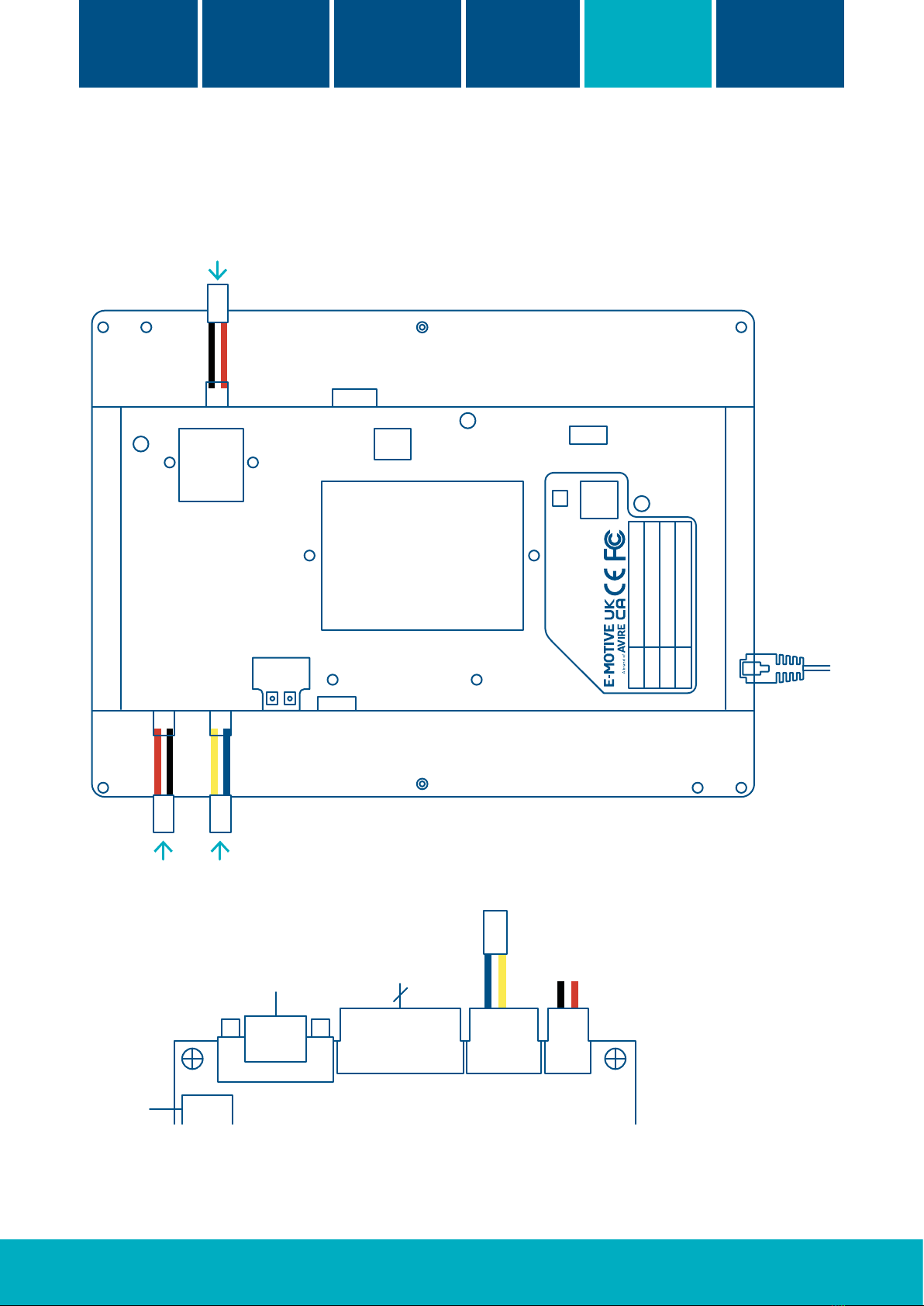
4. Prepare 1 x Mains (110/230VAC) socket and connect to PSU
135-0-1-0022. Connect power supply to PWR IN (P1/P2) on
the ATOM LCD unit.*
5. Mount the speakers on the car-top, with the speakers
facing into the car and connect to ATOM unit using AUD L/R
connections.
6. If there is an Open frame application, follow step 1 to 4 for
the mounting and use the HDMI & 12VDC outputs on the
display to provide HDMI and power to the slave screen.
7. For connected displays, connect the VDSL Tail unit to the
display using the LAN connection and ensure VDSL Head/Tail
are correctly congured using the dipswitch selection on the
VDSL units. The VDSL Tail can be powered by the 12V or 5V
output on the display.
Caution
+Risk of electric shock. Never
remove the casing of the unit
+Ensure that the power supply is
connected properly and that the
voltage is correct before turning
on the system.
+Handle LCD unit with care. Do not
knock or place heavy object on the
top surface of the LCD unit
+Avoid direct contact with heat
dissipating components e.g. heat sink
+PSU 135-0-1-0022 has selectable AC
voltage inputs. Always ensure this
is checked before connecting the
display
+Do not operate this product in
potentially explosive atmospheres
Before
You start
Mechanical
installation
Quick setup
guide
Wiring and
connections
Network
overview
Technical
specication
*Please adhere to instructions on power supply. If using third party PSU, note that funtionality of power outputs (12V/5V) may be eected.
Power from
external power
supply
This manual suits for next models
7
Table of contents
Other AVIRE Monitor manuals