Avital 4003 User manual

Model 4003
Installation Guide
NOTE:
This product is intended for installation by a profes-
sional installer only! Any attempt to install this product by any
person other than a trained professional may result in severe
damage to a vehicle’s electrical system and components.
© 2009 Directed Electronics, Vista, CA
N4003L 2009-04
Avital

Bitwriters with a date code of 6a or older require an IC upgrade
(p/n 998M). Some Bitwriters with a date code of 6B do not
require the IC upgrade. Refer to tech tip # 1112 for more
information. Also required, the Bitwriter T-harness included in
the chip version 2.6 kit (998U).
Bitwriter®, Code Hopping™, Doubleguard®, ESP™, FailSafe®, Ghost
Switch™, Learn Routine™, Nite-Lite®, Nuisance Prevention® Circuitry, Reveng-
er®, Silent Mode™, Soft Chirp®, Stinger®, Valet®, Vehicle Recovery System®,
VRS®, and Warn Away® are all Trademarks or Registered Trademarks of Di-
rected Electronics.
The Bitwriter® (p/n 998U)
requires chip version 2.6 or
newer to program this unit.

Contents
Warning! safety first..........................................................................................1
What is included...............................................................................................3
Installation points to remember............................................................................4
Virtual tach ..............................................................................................5
D2D........................................................................................................5
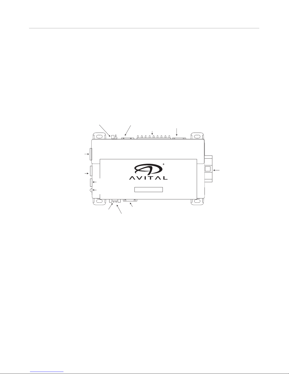
Component locations and finding wires ...............................................................6
Making your wiring connections .........................................................................6
Primary harness (H1) wiring diagram..........................................................7
4-pin satellite harness diagram ...................................................................7
Heavy gauge relay wiring diagram ............................................................7
Door lock harness, 3-pin connector* ...........................................................8
Remote start harness (H2) wiring diagram ...................................................8
Primary harness (H1), 9-pin connector .................................................................8
Heavy gauge relay interface ............................................................................14
Remote start harness (H2), 5-pin connector.........................................................15
Neutral safety switch interface ..........................................................................18
D2D and programmer interface ........................................................................19
Programming jumpers......................................................................................20
Light flash (+)/(-).....................................................................................20
Activation Input (+)/(-) .............................................................................20
Plug-in program switch.....................................................................................21
Tach learning..................................................................................................21
Virtual tach programming ........................................................................21
To learn the tach signal............................................................................22
Tach threshold on/off ..............................................................................22
How to reset features and virtual tach .......................................................23
Operating settings learn routine ........................................................................25
Features menu ................................................................................................27
Menu 1 .................................................................................................27
Feature descriptions.........................................................................................29
Menu 1 .................................................................................................29
Menu 2 .................................................................................................31
Bitwriter® ..............................................................................................34
Shutdown diagnostics......................................................................................35
Safety check...................................................................................................36
Troubleshooting ..............................................................................................38
Wiring quick reference guide ...........................................................................41


1
© 2009 Directed Electronics. All rights reserved.
Warning! safety first
The following safety warnings must be observed at all times:
Due to the complexity of this system, installation of this product must only be•
performed by an authorized Directed Electronics dealer.
When properly installed, this system can start the vehicle via a command•
signal from the remote control. Therefore, never operate the system in an
area that does not have adequate ventilation.
The following precautions are the sole responsibility of the user; however, autho-
rized Directed Electronics dealers should:
Never use a test light or logic probe when installing this unit. Always use•
a multimeter.
Never operate the system in an enclosed or partially enclosed area without•
ventilation (such as a garage).
When parking in an enclosed or partially enclosed area or when having•
the vehicle serviced, the remote start system must be disabled using the
installed toggle switch. It is the user’s sole responsibility to properly handle
and keep out of reach from children all remote controls to assure that the
system does not unintentionally remote start the vehicle.
USER MUST INSTALL A CARBON MONOXIDE DETECTOR IN OR ABOUT•
THE LIVING AREA ADJACENT TO THE VEHICLE. ALL DOORS LEADING
FROM ADJACENT LIVING AREAS TO THE ENCLOSED OR PARTIALLY
ENCLOSED VEHICLE STORAGE AREA MUST REMAIN CLOSED AT ALL
TIMES.
Use of this product in a manner contrary to its intended mode of operation may
result in property damage, personal injury, or death. Except when performing
the Safety Check outlined in this installation guide, (1) Never remotely start the
vehicle with the vehicle in gear, and (2) Never remotely start the vehicle with the
keys in the ignition. The user is responsible for having the neutral safety feature
of the vehicle periodically checked, wherein the vehicle must not remotely start
while the car is in gear. This testing should be performed by an authorized
Directed Electronics dealer in accordance with the Safety Check outlined in this
product installation guide. If the vehicle starts in gear, cease remote start opera-

2© 2009 Directed Electronics. All rights reserved.
tion immediately and consult with the user to fix the problem immediately.
After the remote start module has been installed, test the remote start module
in accordance with the Safety Check outlined in this installation guide. If the
vehicle starts when performing the Neutral Safety Shutdown Circuit test, the
remote start unit has not been properly installed. The remote start module must
be removed or properly reinstalled so that the vehicle does not start in gear. All
installations must be performed by an authorized Directed Electronics dealer.
OPERATION OF THE REMOTE START MODULE IF THE VEHICLE STARTS IN
GEAR IS CONTRARY TO ITS INTENDED MODE OF OPERATION. OPERAT-
ING THE REMOTE START SYSTEM UNDER THESE CONDITIONS MAY RESULT
IN PROPERTY DAMAGE OR PERSONAL INJURY. IMMEDIATELY CEASE THE
USE OF THE UNIT AND REPAIR OR DISCONNECT THE INSTALLED REMOTE
START MODULE. DIRECTED ELECTRONICS WILL NOT BE HELD RESPONSIBLE
OR PAY FOR INSTALLATION OR REINSTALLATION COSTS.

3
© 2009 Directed Electronics. All rights reserved.
What is included
The control module (see diagram below)•
A push-button programming switch•
A hood pinswitch•
A shut-down toggle switch•
AVISTART 4003
BLUE 2-pin port
Status LED
3-pin-2 wire door lock harness*
5-pin remote start
harness
Jumper activation
input polarity 9-pin main harness
4-pin satellite harness
Red 4-pin D2D/Bitwriter port
Jumper tachometer
threshold Jumper light ash polarity
6-pin relay output
4 pin, 3 wire receiver port*
*Available only when adding a reciever (P/N 543H) and remote (P/N 474L).

4© 2009 Directed Electronics. All rights reserved.
Installation points to remember
Important:
This product is designed for fuel-injected,
automatic transmission vehicles only. Installing it in a
standard transmission vehicle is dangerous and is con-
trary to its intended use.
Before beginning the installation:
Please read this entire installation guide before beginning the in-•
stallation. The installation of this remote start system requires in-
terfacing with many of the vehicle’s systems. Many new vehicles
use low-voltage or multiplexed systems that can be damaged by
low resistance testing devices, such as test lights and logic probes
(computer safe test lights). Test all circuits with a high quality digital
multi-meter before making connections.
Do not disconnect the battery if the vehicle has an anti-theft-coded•
radio. If equipped with an air bag, avoid disconnecting the bat-
tery if possible. Many airbag systems will display a diagnostic
code through their warning lights after they lose power. Discon-
necting the battery requires this code to be erased, which can
require a trip to the dealer.
Remove the dome light fuse. This prevents accidentally draining•
the battery.
Roll down a window to avoid being locked out of the vehicle.•
After the installation: Test all functions. The “Using Your System”•
section of the Owner’s Guide is very helpful when testing.
Complete the vehicle• Safety Check outlined in this manual prior
to the vehicle reassembly.

5
© 2009 Directed Electronics. All rights reserved.
➢Virtual tach
Virtual Tach is the default RPM-sensing method for new remote start
systems. Virtual Tach gives the installer the performance of a hardwired
tach wire, with the convenience of voltage sensing. It is far superior to
any voltage-sense feature you’ve tried before.
Virtual Tach monitors the cranking voltage of the vehicle using a very
fast micro-controller and an analog-to-digital converter. The micropro-
cessor “saves” the base voltage as a reference. When Virtual Tach
“sees” the slightest uptick in voltage, indicating that the alternator is
charging the battery, the starter motor shuts off instantly.
➢D2D
The system has the ability to interface with an Xpresskit module through
the D2D port. The advantage to using a D2D interface is that there
is less wiring involved in the installation. Check the Xpresskit module
installation guide to determine which wires are not needed, and which
options are available.

6© 2009 Directed Electronics. All rights reserved.
Component locations and finding wires
For detailed information on where to locate components, and how
to find the wires you need, please refer to the Direct Tech web site at
www.directechs.com.
Making your wiring connections
Before making your connections, plan how your wires will be routed
through the vehicle. For instance, the red 12V constant input and the re-
mote start ignition wires are often routed together to the ignition switch
harness. In order to keep the wiring neat and make it harder to find,
you may wish to wrap these wires together in electrical tape or conceal
them in tubing similar to what the manufacturer used.
There are two acceptable ways of making a wire connection - solder
connections and crimp connectors. When properly performed, either
type of connection is reliable and trouble-free. Regardless of whether
you solder your connections or you use mechanical type crimp-on con-
nections, ensure that all connections are mechanically sound and that
they are insulated, especially when connecting data lines in the ve-
hicle.
Cheap electrical tape, especially when poorly applied, is not a reli-
able insulator. It often falls off in hot weather. Use good quality electri-
cal tape or heat shrink.
Never twist-and-tape the wires together without soldering.•
Never use “fuse taps”, as they can damage fuse box terminals.•
If you use tapping connectors such as T-Taps (not to be confused with
Scotch-Locks), avoid using them in higher-current applications (constant
12V, ground, etc.) These connectors are inferior in quality and should
be avoided.

7
© 2009 Directed Electronics. All rights reserved.
➢Primary harness (H1) wiring diagram
H1/1 LIGHT GREEN/
BLACK
(-) FACTORY ALARM DISARM
H1/2 GREEN/WHITE (-) FACTORY ALARM REARM
H1/3 YELLOW (+) IGNITION OUT (TO ALARM)
H1/4 WHITE/BLUE (+/-) ACTIVATION INPUT
H1/5 ORANGE (-) GROUND WHEN LOCKED*
H1/6 BROWN (-) HORN OUTPUT*
H1/7 RED/WHITE (-) TRUNK RELEASE OUTPUT*
H1/8 BLACK GROUND
H1/9 WHITE (+/-) LIGHT FLASH
* Available only when adding a receiver (P/N 543H) and remote
(P/N 474L).
➢4-pin satellite harness diagram
1BLUE (-) STATUS OUTPUT
2ORANGE (-) ACCESSORY OUTPUT
3PURPLE (-) STARTER OUTPUT
4PINK (-) IGNITION OUTPUT
➢Heavy gauge relay wiring diagram
1PINK (+) OUTPUT TO IGNITION CIRCUIT
2PURPLE (+) OUTPUT TO STARTER CIRCUIT
3ORANGE (+) OUTPUT TO ACCESSORY CIRCUIT
4RED (+) (30A) HIGH CURRENT 12 INPUT
5PINK/WHITE (+) PROGRAMMABLE OUTPUT FOR ACCESSORY OR IGNITION
6RED (+) (30A) HIGH CURRENT 12V INPUT

8© 2009 Directed Electronics. All rights reserved.
➢Door lock harness, 3-pin connector*
1BLUE (-) UNLOCK OUTPUT
2EMPTY NOT USED
3GREEN (-) LOCK OUTPUT
*Available only when adding a receiver (P/N 543H) and remote
(P/N 474L).
➢Remote start harness (H2) wiring diagram
H2/1 BLACK/WHITE (-) NEUTRAL SAFETY SWITCH INPUT
H2/2 VIOLET/WHITE TACHOMETER INPUT WIRE
H2/3 BROWN (+) BRAKE SWITCH SHUTDOWN WIRE
H2/4 GRAY (-) HOOD PINSWITCH SHUTDOWN WIRE
H2/5 BLUE/WHITE (-) 200mA 2ND STATUS/REAR DEFOGGER OUTPUT
Primary harness (H1), 9-pin connector
H1/1 LIGHT GREEN/
BLACK
(-) FACTORY ALARM DISARM
This wire sends a negative pulse every time the remote start is activated
or the doors are unlocked. This can be used to pulse the disarm wire
of the vehicle’s factory anti-theft device. Use a relay to send a (-) or (+)
pulse to the disarm wire as shown in the following diagrams.

9
© 2009 Directed Electronics. All rights reserved.
Relay for Negative (-) Disarm Wire
Relay for Positive (+) Disarm Wire

10 © 2009 Directed Electronics. All rights reserved.
H1/2 GREEN/WHITE (-) FACTORY ALARM REARM
This wire sends a negative pulse every time the remote start shuts down
or the doors are locked. This can be used to pulse the arm wire of the
vehicle’s factory anti-theft device. Use a relay to send a (-) or (+) pulse
to the arm wire.
H1/3 YELLOW (+) IGNITION OUT (TO ALARM)
The H1/3 YELLOW wire is connected to the ignition input of the host
security or keyless entry system.
Disconnect the ignition/accessory input of the remote controlled secu-
rity or keyless entry system. Connect the H1/3 YELLOW ignition output
to the ignition/accessory input of the remote controlled security or key-
less entry system. The wire will prevent the host system from sensing that
the ignition is on during remote start operation.
H1/4 WHITE/BLUE (+/-) ACTIVATION INPUT
This input comes from the factory set to 1 activation pulse. This means
that it is necessary to have 1 positive or ground pulse (see the Pro-
gramming jumper section of this guide) on the white/blue wire for the
remote start to activate or to deactivate. This wire will be connected to
a security or keyless entry system.
Note:
The activation pulse count can be programmed to 1, 2, or 3
pulses.

11
© 2009 Directed Electronics. All rights reserved.
H1/5 ORANGE (-) GROUND WHEN LOCKED OUTPUT*
This wire supplies a (-)500 mA ground as long as the system is locked
and when the remote start is activated. (This feature can be turned off
by programming the anti-grind option Off). This output ceases as soon
as the system is unlocked. The GWA can be hooked up to an optional
starter kill/anti-grind relay control module, a voice module or any ac-
cessory that requires a ground when armed.
*Available only when adding a receiver (P/N 543H) and remote
(P/N 474L).
H1/6 BROWN (-) HORN OUTPUT*
This wire supplies a (-) 200 mA output that can be used to honk the
vehicle horn. It outputs a single pulse when locking the doors with the
remote, and two pulses when unlocking with the remote. This wire also
outputs pulses for 30 seconds when Panic Mode is activated. If the
vehicle has a (+) horn circuit, an optional relay can be used to interface
with the system.
*Available only when adding a receiver (P/N 543H) and remote
(P/N 474L).

12 © 2009 Directed Electronics. All rights reserved.
H1/7 RED/WHITE TRUNK RELEASE (-) 200 mA OUTPUT*
When the system receives the code controlling trunk release, for longer
than 1.5 seconds, the RED/WHITE wire will supply an output as long
as the transmission continues. This is often used to operate a trunk/
hatch release or other relay-driven function.
*Available only when adding a receiver (P/N 543H) and remote
(P/N 474L).
H1/8 BLACK (-) CHASSIS GROUND CONNECTION
We recommend that you do not use a factory ground. Ground all
your components to the same point in the vehicle, (preferably the kick
panel). Scrape away any paint and use a factory bolt or make your
own ground with a self-tapping screw and a star washer.
H1/9 WHITE (+/-) LIGHT FLASH OUTPUT
Important:
Do NOT connect this wire to a negative
vehicle light flash wire before changing the program-
ming jumper to the negative polarity position or dam-
age to the vehicle light circuit may occur.
As factory configured, the H1/9 WHITE wire should be connected to
the (+) parking light wire. If the light flash polarity jumper is moved to
the (-) position (refer to the Programming Jumper section of this guide),
this wire then supplies (-) 200mA output.

13
© 2009 Directed Electronics. All rights reserved.
Note:
For parking light systems that draw 10 amps or more, the jump-
er must be placed to the (-) light flash output (refer to the Programming
Jumpers section of this guide.) P/N 8617 or a standard automotive
SPDT relay must be used on the H1/2 light flash output wire.
(+) Positive Light Flash Output
(-) Light Flash Output

14 © 2009 Directed Electronics. All rights reserved.
Heavy gauge relay interface
The heavy gauge wires are used to energize high current circuits in the
vehicle. It is crucial that these connections are made correctly so that
they are capable of handling the current demands. For this reason,
scotch locks, T-taps and other such connectors should not be used.
1PINK (+) OUTPUT TO IGNITION CIRCUIT
Connect this wire to the ignition wire in the vehicle.
2PURPLE (+) OUTPUT TO STARTER CIRCUIT
Connect this wire to the starter wire in the vehicle.
3ORANGE (+) OUTPUT TO ACCESSORY CIRCUIT
Connect this wire to the accessory wire in the vehicle that powers the
climate control system.
4 & 6 RED (+) (30A) HIGH CURRENT 12V INPUT
Remove the two 30 amp fuses prior to connecting these wires and do
not replace them until the control module is ready to be tested. These
wires are the source of current for all onboard remote start relays and
the main unit. They must be connected to a high current source. Since
the factory supplies (+) 12V to the key switch that is used to operate the
motor, it is recommended that these wires be connected there.
Note:
If the factory supplies two separate (+) 12V feeds to the igni-
tion switch, connect one RED wire of the satellite to each feed at the
switch.

15
© 2009 Directed Electronics. All rights reserved.
5PINK/WHITE (+) PROGRAMMABLE OUTPUT FOR ACCESSORY OR IGNITION
Connect this wire to the second ignition or accessory wire in the vehicle.
(Selectable by using menu 2 feature 6.)
Note:
For vehicles that do not have a second ignition or accessory
wire, this connection is not required.
Remote start harness (H2), 5-pin connector
H2/1 BLACK/WHITE (-) NEUTRAL SAFETY SWITCH INPUT
Connect this wire to the toggle (override) switch as shown in Figure A.
Connect the other wire from the toggle switch to the PARK/NEUTRAL
switch in the vehicle. This wire will test with ground with the gear selector
either in PARK or NEUTRAL. This will prevent the vehicle from accidentally
being started while in a drive gear. This input MUST rest at ground in order
for the remote start system to operate. Connected properly the vehicle will
only start while in PARK or NEUTRAL.
In some vehicles, the PARK/NEUTRAL position switch activates a fac-
tory starter lock-out that will not allow the starter to operate in a drive
gear. In these vehicles, connect this wire to the toggle switch as shown
in Figure B on the following page. Connect the other wire from the
toggle switch to chassis ground.

16 © 2009 Directed Electronics. All rights reserved.
Figure A
Figure B
Important!
Always use the Vehicle Safety Check section of this guide to
verify that the vehicle cannot be started in ANY drive gear and that the
override switch is functioning properly.
H2/2 VIOLET/WHITE TACHOMETER INPUT WIRE
This input provides the module with information about the engine’s revo-
lutions per minute (RPMs). It can be connected to the negative side of
the coil in vehicles with conventional coils. In multi-coil and high energy
ignition systems locating a proper signal may be more difficult. Once
connected, you must teach the system the tach signal. (See
Tach Learn-
ing
section of this guide.)
Table of contents
Other Avital Car Alarm manuals

Avital
Avital Hurricane 2 User manual

Avital
Avital AVISTART 3001 User manual

Avital
Avital AviStart 6500 User manual

Avital
Avital Remote Access User manual

Avital
Avital 2200 User manual

Avital
Avital Hurricane User manual

Avital
Avital AviStart 3100 User manual

Avital
Avital 5103 User manual

Avital
Avital 4300 User manual

Avital
Avital Phoenix 2 User manual

Avital
Avital 4103 User manual

Avital
Avital Phoenix 2 User manual

Avital
Avital 4118L User manual

Avital
Avital AviStart 6000 User manual

Avital
Avital Hurricane 3 User manual

Avital
Avital 4100 User manual

Avital
Avital 2100 User manual

Avital
Avital AviStar 3300 User manual

Avital
Avital AviStart 6001 User manual

Avital
Avital Tornado User manual