AVPro Edge AC-MXNET-1G-E AVDM User manual

SETUP AND CONFIGURATION GUIDE

AVPro Edge ~ 2222 E 52nd ST N, Sioux Falls, SD, 57104 ~1.877.886.5112 ~ +1.605.274.6055 ~ [email protected]om 2 of 29
Table of Contents
Welcome to MXNet .............................................................................................................................................3
Technical Specifications.......................................................................................................................................4
Network Cabling Tips...........................................................................................................................................6
Getting Organized ...............................................................................................................................................7
Hardware............................................................................................................................................................8
Control Box .....................................................................................................................................................8
Encoders, Inputs & Sources .............................................................................................................................9
What’s in the box........................................................................................................................................11
Decoders, Outputs & Displays ........................................................................................................................11
What’s in the box........................................................................................................................................13
MXNet Mentor - Construct, Configure, Create & Control....................................................................................... 14
Home Page ...................................................................................................................................................15
Configure Page..............................................................................................................................................16
Inputs/Encoders/Sources ...........................................................................................................................16
Outputs/Decoders/Displays ........................................................................................................................17
Configure Page ~ Diagnostics......................................................................................................................... 18
Encoder Diagnostics................................................................................................................................... 18
Decoder Diagnostics ..................................................................................................................................19
Auto-Matrix Page ...........................................................................................................................................20
Video Wall Page.............................................................................................................................................21
Advanced Pages ...........................................................................................................................................22
CEC/HDMI & RS-232/IP Page.....................................................................................................................22
RS-232 & IR Direct Page ............................................................................................................................23
USB & KVM ...............................................................................................................................................24
Warranty ...........................................................................................................................................................25

AVPro Edge ~ 2222 E 52nd ST N, Sioux Falls, SD, 57104 ~1.877.886.5112 ~ +1.605.274.6055 ~ [email protected]om 3 of 29
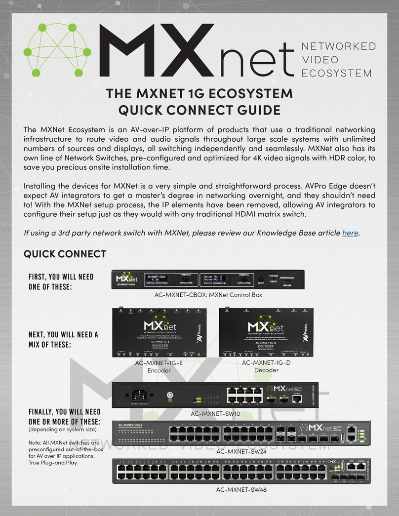
Welcome to MXNet
MXNet is a fresh approach to the Audio/Video Over IP product category. We’ve taken our vast experience with
video distribution solutions, conducted extensive research into current offerings, and re-engineered how
Audio/Video Over IP is configured, constructed, deployed and controlled.
The result is a system which is remarkably easy to build any size system - from residences, classrooms, light
commercial all the way up to casinos or even stadiums which hundreds of decoders/end point.
•The ease-of-use magic to this system begins with our advanced hardware engineering and industry
leading software interface designs. Attention to every detail is evident with the design of our encoders
and decoders. Some of the advancements include:
•an all-aluminum chassis which efficiently dissipates heat eliminating the need for cooling fans
•a proprietary front mini-OLED display “Data Window” providing critical system information such as the
encoder/decoder IP address and Custom Name assignments.
•Light controls on each encoder and decoder: On, Flash, and Off ( including those pesky network data
lights )!
•Only 3-6 Watts POE power consumption! ( 802.3af compliant )
•From 720P up to 4K/HDR/Dolby Vison® video output.
•JPEG 2000 video encoding/decoding
Our HTML5 Web GUI is a best-in-class effort with simply powerful features and unparalleled ease of use. It
makes setting up an MXNet system a breeze.

AVPro Edge ~ 2222 E 52nd ST N, Sioux Falls, SD, 57104 ~1.877.886.5112 ~ +1.605.274.6055 ~ [email protected]om 4 of 29
Technical Specifications
SKU AC-MXNET-1G-E (& AVDM) AC-MXNET-1G-D AC-MXNET-CBOX
Category
Encoder (Transmitter)
Decoder (Receiver)
Controller
Video
Signal Type
DVI 1.0, HDMI 2.0b
DVI 1.0, HDMI 2.0b
N/A
Video Resolution
4K@60Hz 4:4:4*
4K@30Hz 4:4:4
4K@60Hz 4:2:0
4K@60Hz 4:4:4*
4K@30Hz 4:4:4
4K@60Hz 4:2:0
N/A
HDR format
HDR 10, HLG, DV
HDR 10, HLG, DV
N/A
Chroma Subsampling
444, 422, 420
444, 422, 420
N/A
Bit Depth per Color
1080p (16 Bit)
4K (10, 12 Bit)
1080p (16 Bit)
4K (10, 12 Bit)
N/A
Audio
Audio Format
PCM 2, 5.1, 7.1 Channel,
Dolby Digital 5.1 Channel,
Dolby Digital Plus, DTS 5.1
Channel, DTS–ES, DTS–HD
High Resolution
PCM 2, 5.1, 7.1 Channel,
Dolby Digital 5.1
Channel, Dolby Digital
Plus, DTS 5.1 Channel,
DTS–ES, DTS–HD High
Resolution
N/A
Embedded Audio
Stereo analog audio
N/A
N/A
De-embedded Audio
Balanced analog audio
Stereo analog audio
N/A
Ports
Ethernet
(1) × female RJ-45, PoE
(2) × female RJ-45, one
with PoE
SFP
(1) × SFP Slot
(1) × SFP Slot
0
HDMI
(2) × HDMI Type A 19-pin,
female, one HDMI input, one
HDMI loop out
(1) × HDMI Type A 19-
pin, female, one HDMI
output
N/A
Audio
(1) × 5 Pin Terminal Block,
Balanced L/R Audio out
(1) × 3.5 mm mini stereo
jack, Audio in
(1) × 3.5 mm mini stereo
jack, Audio out
N/A
IR
(3) × 3.5mm mini-stereo
jack, one IR-Pass, one IR-
EYE, one IR-out
(3) × 3.5mm mini-stereo
jack, one IR-Pass, one
IR-EYE, one IR-out
N/A
RS-232
(1) × 5 Pin Terminal Block
(1) × 5 Pin Terminal
Block
(1) × 5 Pin Terminal
Block for MXNET
system control

AVPro Edge ~ 2222 E 52nd ST N, Sioux Falls, SD, 57104 ~1.877.886.5112 ~ +1.605.274.6055 ~ [email protected]om 5 of 29
USB
(1) × USB 2.0 Type-B for
USB extension and KVM, (1)
× USB Micro Type-B for
MXNET service
(2) × USB 2.0 Type-A for
USB extension and KVM,
(1) × USB Micro Type-B
for MXNET service
(1) × USB Micro Type-B
for MXNET service
Distance
Ethernet
100 Meters/ 330 Feet over
CAT5e and above
100 Meters/ 330 Feet
over CAT5e and above
100 Meters/ 330 Feet
over CAT5e and above
SFP and Fiber
1000BASE-SX SFP
Transceiver Module (MMF,
850nm, 550m, LC, DOM)
1000BASE-SX SFP
Transceiver Module
(MMF, 850nm, 550m, LC,
DOM)
N/A
1000BASE-LX/LH SFP
1310nm 10km Transceiver
Module
1000BASE-LX/LH SFP
1310nm 10km
Transceiver Module
N/A
System
Max Power Consumption
6.5W (AVDM 9.5W)
9W
4.5W
PoE (Power over Ethernet)
IEEE 802.3af (15.4W)
Power Supply Unit
Input: AC 120-240V-
50/60Hz 0.8A
Output: DC 12V 2A
Input: AC 120-240V-
50/60Hz 0.8A
Output: DC 12V 2A
Input: AC 120-240V-
50/60Hz 0.5A
Output: DC 5V 2A
Operating Temperature
23 TO 125°F (-5 to 51℃)
Storage Temperature
-4 to 140°F (-20 TO 60℃)
-4 to 140°F (-20 TO
60℃)
Operating Humidity
5-90% RH (No
Condensation)
5-90% RH (No
Condensation)
5-90% RH (No
Condensation)
Mounting
Rack and furniture mount
support
Rack and furniture mount
support
Rack and furniture
mount support
Dimension
(Unit/Width/Depth/Height)
MM: 200×104×20
Inches: 7.87×4.09×0.79
MM: 200×104×20
Inches: 7.87×4.09×0.79
MM: 136×86×40
Inches: 5.35×3.39×1.57
Dimension
(Packaged/Width/Depth/Height)
MM: 310×180×54
Inches:12.20×7.09×2.13
MM: 310×180×54
Inches:12.20×7.09×2.13
MM: 310×180×54
Inches:12.20×7.09×2.13
Weight (Unit)
0.55KG
0.55KG
0.57KG
Weight (Packaged)
0.77KG
0.77KG
0.79KG
Regulatory
CE/FCC/UL
CE/FCC/UL
CE/FCC/UL
Product Warranty
10 Years
10 Years
10 Years
*4K60 4:4:4/4K60 4:2:2 Use ICT Compression

AVPro Edge ~ 2222 E 52nd ST N, Sioux Falls, SD, 57104 ~1.877.886.5112 ~ +1.605.274.6055 ~ [email protected]om 6 of 29
Network Cabling Tips
1. EVERTHING about a successful MXNet installation revolves around the network cables including:
• The quality of the cable
• The distance of the connection
• The handling of the cable
• The video resolution expected
• The higher the resolution, the better the cable should be
• The longer the run, the better the cable should be
2. When terminating network cable do not untwist the wires unnecessarily.
• Wires are twisted for good reasons:
• Cancels out EMI (Electromagnetic Interference)
• Cancels out crosstalk from neighboring conductors
• Make sure not to untwist more than a ½ inch (preferably ¼ inch)
• Remove as little of the sheath as possible
• Terminate with traditional connectors – avoid “EZ” types.
3. Handle cables with care
• NO tight tie wraps
• NO clamping or stapling
• Tie cables loosely with appropriate cable wraps
• If you need to pull, don’t pull too hard – may cause pairs to untwist – degrade performance
• Do not overbend cables – ¼ inch cable radius = 2” bend radius
4. Keep network cables away from power sources
5. Do not use patch cords unnecessarily
6. Test, Test, Test
7. Be Organized

AVPro Edge ~ 2222 E 52nd ST N, Sioux Falls, SD, 57104 ~1.877.886.5112 ~ +1.605.274.6055 ~ [email protected]om 7 of 29
Getting Organized
With MXNet, you are not required to connect the encoders and decoders in any specific order on the network
switch. In fact, the system is extremely accommodating to the point that you could connect and place encoders
and decoders on adjacent ports right next to each other, and MXNet would function as expected without
issues.
However, for best results (especially with troubleshooting highly complex systems with dozens of end
points/outputs) a certain degree of design and planning is required . . .
Here are some suggestions:
• Create a diagram/flow chart indicating the network cable run starting points and destinations.
• Label each cable run on both ends to indicate the location of source inputs and outputs.
• Use zip ties to neatly but loosely bundle together the encoder and decoder cable runs. This method will
help with mitigating the “Spaghetti Effect”.
• Create any supporting “as-built” documentation to go with your schematics and diagrams, so that an
Archeologist in the future will be able to understand what you were doing.
• Plan ahead . . .
• MXNet allows you to assign custom names for each Encoder and Decoder.
oThe Custom Names are limited to 12 characters, plus there is a 12 character “DESCRIPTION”
field to provide further details about the INPUT or OUTPUT device.
oWith larger projects you may need to get a bit creative with how you assign a custom name to
each Encoder and Decoder.
oAlthough not required, best practices suggest that the Encoder cables be grouped next to each
other on the network switch - followed by similarly grouping the Decoders.

AVPro Edge ~ 2222 E 52nd ST N, Sioux Falls, SD, 57104 ~1.877.886.5112 ~ +1.605.274.6055 ~ [email protected]om 8 of 29
Hardware
Control Box
( AC-MXNET-CBOX )
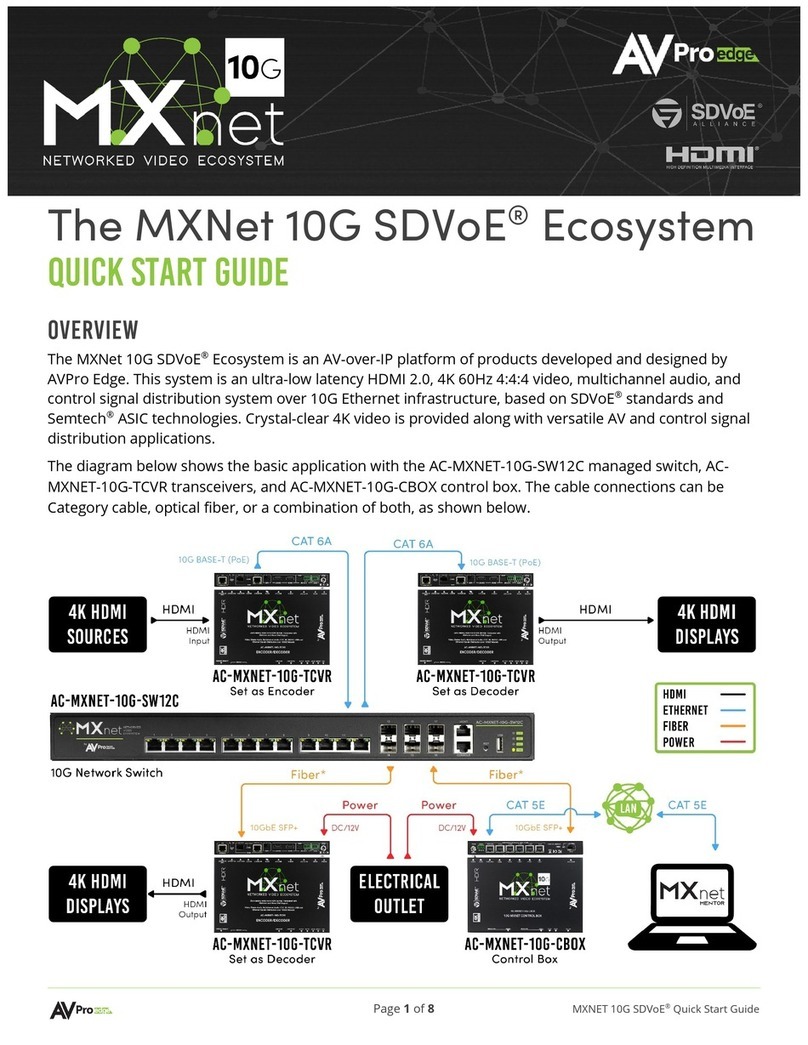
The MXNet CBOX (Control Box) is designed to provide multipoint AV over IP distribution and control routing
capabilities for a wide variety of multicast ready network data switches. The state-of-the-art HTML 5 web based
“MXNet Mentor”app provides a full featured environment for setting up an MXNet system with great efficiency.
(FRONT)
BPOWER indicator light
CToggle: DHCP / Static IP setting
DSYSTEM RESET – use a paperclip or pen – click and hold for 7 seconds - RESET to
factory defaults.
(BACK)
E LAN 1 (POE) / AV OVER IP – supports a POE power source and is plugged into the designated Control
Traffic port on the network switch.
F LAN 2 (CTRL) / SYS. CONTROL – connects to the LAN or a control system
CPU/Processor.
G SYS. CTRL. / RS-232 – three pin terminal block for connecting to CBOX and controlling
system using RS-232.
H PROPRIETARY ISP/USB – service port – AVPro use ONLY.
I Optional POWER - locking ring – 5V / 1A charging block (included in box). Not necessary when
connected to a POE+ network switch which will provide the any power required.

AVPro Edge ~ 2222 E 52nd ST N, Sioux Falls, SD, 57104 ~1.877.886.5112 ~ +1.605.274.6055 ~ [email protected]om 9 of 29
(TOP)
Encoders, Inputs & Sources
( AC-MXNET-1G-E )
The MXNet Encoder is the starting point where all sources and hosts are connected for distribution of audio
and video signals to the end points at the other end of the connection. Video sources, audio sources, USB
hosting for KVM functions, RS-232 encapsulated control, RS-232 direct passthrough, and IR passthrough all
start at the Encoder. With only 3-5 watts of power usage, the POE powered AC-MXNET-1G-E sets a standard
for efficiency. The only thing missing? The fan. That’s correct, there’s no cooling fan because both of our
MXNet Encoders AND Decoders use an integrated metal chassis and chip-top heatsinks to efficiently disperse
heat.. The entire internal frame acts like one giant heatsink. On the next few pages, we will breakdown the
plethora of connections waiting to be discovered . . .
(FRONT)
B POWER indicator light. During booting, the light will slowly pulsate until the incoming power (POE or
charger) stabilizes. At that point it will turn to a solid blue light.
C LINK / SINK indicator light. This light will flash green until it connects to a Decoder at
which point it will turn to a solid green light.
D EDID COPY FROM HDMI LOOP OUT – copies the EDID of the display
connected to the HDMI Loop Out connector on the back of
Encoder.
ERS-232 signal passthrough and routing from an RS-232 (BOTTOM)
bridge to any Decoder.
F IR IN / I-PASS / IR-EYE – IR signal passthrough using two
methods: I-PASS which allows for a 3.5mm direct connect
of an IR emitter from an IR bridge or control system CPU or
processor.
G IR IN / R-EYE supports taking a flashing IR emitter from

AVPro Edge ~ 2222 E 52nd ST N, Sioux Falls, SD, 57104 ~1.877.886.5112 ~ +1.605.274.6055 ~ [email protected]om 10 of 29
an IR bridge or control system CPU and attaching the
emitter to an IR decoder - which is plugged into the 3.5mm
IR-EYE port - and then routed to any Decoder.
H IR OUT – for receiving IR signals upstream from a
Decoder
I IP MONITOR – OLED “DATA WINDOW”. Displays the
Encoder’S IP address and Custom Name or
MAC address. MXNet / AVPro exclusive and proprietary.
J EDID SETTINGS – Override the MXNet Mentor settings
and permanently set a generic EDID. See EDID setting chart on
bottom of the
Encoder.
K PROPRIETARY FPGA / MCU debug settings. AVPro service ONLY.
L USB – AVPro service port ONLY.
(BACK)
M 1GbE NETWORK port. POE supported. Connected from the Encoder to the network switch. A network
switch which supports POE is highly recommended.
N BI DIR. O.M. LC FIBER – Fiber connection for extremely long runs. Requires a fiber extender kit or a
network switch with fiber ports.
O HDMI LOOP OUT – mirrored uncompressed signal to display.
P HDMI IN – source input.
Q AUDIO OUT - BALANCED analog stereo.
R AUDIO IN – 3.5mm
S USB HOST - locking ring – 5V / 1A charging block (included in box). Not needed if the network switch is
providing power
via POE.
T RESET port – use a paperclip or similar object. Resets the Encoder to factory
configuration.
UPOWER – locking POWER supply / charger. Not required if the network switch is providing POE power.
( DC 12v/2a )
(BOTTOM)

AVPro Edge ~ 2222 E 52nd ST N, Sioux Falls, SD, 57104 ~1.877.886.5112 ~ +1.605.274.6055 ~ [email protected]om 11 of 29
What’s in the box
•AC-MXNET-1G-E
•1 x IR Tx Unit
•1 x IR Rx Unit
•2 x 3-Pin Terminal Blocks
•1 x 5-Pin Terminal Blocks
•Mounting Ears
•Rubber Feet
(TOP)
Decoders, Outputs & Displays
( AC-MXNET-1G-D )
The MXNet Decoder receives all source and host data / signals as they arrive to the end point location.
Distributed audio and video signals are first gathered at the starting point by the Encoder and then routed via
the network switch to the end points at the other end of the connection. Video sources, audio sources, USB
hosting for KVM functions, RS-232 encapsulated control, RS-232 direct passthrough, and IR passthrough all
end at the Decoder. With only 3-5 watts of power usage, the POE powered AC-MXNET-1G-D sets a standard
for efficiency. Again, there’s no cooling fan because both of our MXNet Encoders and Decoders use an
aluminum chassis to disperse heat super efficiently. The entire internal frame acts like one giant heatsink. On
the next few pages, we will breakdown the function and utility of all the connections and ports . . .

AVPro Edge ~ 2222 E 52nd ST N, Sioux Falls, SD, 57104 ~1.877.886.5112 ~ +1.605.274.6055 ~ [email protected]om 12 of 29
(FRONT)
B POWER indicator light and is plugged into the designated Control Traffic port on the network switch.
C LINK / SINK indicator light. This light will flash green until it connects to a Decoder at
which point it will turn to a solid green light.
D EDID COPY FROM HDMI OUT – copies the EDID of the display
connected to the HDMI OUT connector on the back of the Decoder.
E RS-232 – outputs RS-232 signals which are generated using either the RS-232/IP method
or via RS-232 direct passthrough.
F IR IN I-PASS allows for sending direct routing IR signals upstream.
G IR IN IR-EYE allows for sending direct routing IR signals upstream.
H IR OUT – incoming IR signals routed from a designated Encoder.
I IP MONITOR – OLED “DATA WINDOW”. Displays the Decoder’S IP address and
Custom Name or MAC address. MXNet / AVPro exclusive and proprietary.
J USB DEVICES -1 – supports routing the USB 2.0 signal from the Decoder to the
designated HOST Encoder.
K USB DEVICES -2 – supports routing the USB 2.0 signal from the Decoder to the same designated
HOST Encoder.
L PROPRIETARY FPGA / MCU debug settings. AVPro service ONLY.
M USB – AVPro service port ONLY.
(BACK)
N 1GbE NETWORK port. POE supported. Connected from the Decoder to the network switch. A network
switch which supports POE is highly recommended.
O BI DIR. O.M. LC FIBER – Fiber connection for extremely long runs. Requires a fiber extender kit
or a network switch with fiber ports.
P HDMI OUT – output to HDMI port of the display.
Q AUDIO OUT -
R POWER - locking ring – 5V / 1A charging block (included in box). Not required if the
network switch is providing power to the Decoder via POE.

AVPro Edge ~ 2222 E 52nd ST N, Sioux Falls, SD, 57104 ~1.877.886.5112 ~ +1.605.274.6055 ~ [email protected]om 13 of 29
What’s in the box
•AC-MXNET-1G-D
•1 x IR Tx Unit
•1 x IR Rx Unit
•2 x 3-Pin Terminal Blocks
•Mounting Ears
•Rubber Feet

AVPro Edge ~ 2222 E 52nd ST N, Sioux Falls, SD, 57104 ~1.877.886.5112 ~ +1.605.274.6055 ~ [email protected]om 14 of 29
MXNet Mentor - Construct, Configure, Create & Control
MXNet Mentor is AVPro’s proprietary - state-of-the-art - HTML 5 based setup and control app. Mentor is a
complete, full featured solution showcasing a large variety of simple, yet powerful features and functions. The
following pages will provide a comprehensive guide to all the utilities that comprise the MXNet Mentor app and
MXNet Ecosystem.
To experience MXNet Mentor, simply launch any modern web browser – ( Explorer, Safari, Chrome, etc. ) – on
your ( Windows 10, Mac, iOS, or Android ) device, and enter the IP address of the MXNet Control Box.
The default factory IP address is: 192.168.1.239
Username: admin
Password: admin
On the left side of the screen, you will notice a column of icons representing each critical function and utility
available. Simply click or tap on each icon to see. The next several pages extensively cover and explain each
and every function of “MXNet Mentor” staring with the HOME / SYSTEM UTILITIES page.

AVPro Edge ~ 2222 E 52nd ST N, Sioux Falls, SD, 57104 ~1.877.886.5112 ~ +1.605.274.6055 ~ [email protected]om 15 of 29
Home Page
The HOME page provides a variety of MXNet system information including the versions of currently installed
application software and firmware as well as a firmware update/installation portal.

AVPro Edge ~ 2222 E 52nd ST N, Sioux Falls, SD, 57104 ~1.877.886.5112 ~ +1.605.274.6055 ~ [email protected]om 16 of 29
Configure Page
NOTE:You must connect an MXNet Control Box, MXNet Encoders/Encoders, and MXNet Decoders/Decoders
to your network switch prior to attempting to input any information on the CONFIGURE pages. The
CONFIGURE pages will remain blank until that equipment is connected.
Inputs/Encoders/Sources
Looking at the page from left to right you will see the following columns:
NAME (AUTO): ( Example: Tx1, Tx2, Tx3, etc. ) This info is automatically generated by the MXNet control
system for keeping internal track of the connected Encoders. This field is grayed out, and cannot be edited.
CUSTOM NAME: Assign any custom name to a Encoder. You have up to 12 characters available - no spaces.
DESCRIPTION: Enter any text desired. You have up to 12 characters available - no spaces.
EDID MGMT: Choose an EDID which will provide the highest level of compatibility with the target display. In
most cases, a generic lower common denominator EDID such an 1080P 2CH will provide the best
CHANNEL: Each channel number must be unique. The MXNet control system will automatically assign
channel numbers to each Encoder. If you notice a duplicate channel number ( highly unlikely ), then assign a
unique number. You have 9,998 possible combinations.
IP ADDRESS (AUTO): The IP Address is automatically generated by the MXNet control system. This field is
grayed out, and cannot be edited.
MAC ADDRESS: The MAC Address is pre-assigned to each Encoder. This field is grayed out, and cannot be
edited.
Encoder LIGHTS: Encoder lighting controls ( mini-display, PWR, LINK, and Network link/activity ) are actuated
using rotating toggle/clicks: Click once to cause all lights on the Encoder to FLASH, click again to Turn OFF all
lights, and click once more to Turn ON all lights. You have the option to actuate this feature with individual
Encoders or ALL Encoders.

AVPro Edge ~ 2222 E 52nd ST N, Sioux Falls, SD, 57104 ~1.877.886.5112 ~ +1.605.274.6055 ~ [email protected]om 17 of 29
Outputs/Decoders/Displays
Looking at the page from left to right you will see the following columns:
NAME (AUTO): ( Example: Rx1, Rx2, Rx3, etc. ) This info is automatically generated by the MXNet control
system for keeping internal track of the connected Decoders. This field is grayed out, and cannot be edited.
CUSTOM NAME: Assign any custom name to a Decoder. You have up to 12 characters available - no spaces.
DESCRIPTION: Enter any text desired. You have up to 12 characters available - no spaces.
OUTPUT RESOLUTION: Choose an output resolution
IP ADDRESS (AUTO): The IP Address is automatically generated by the MXNet control system. This field is
grayed out, and cannot be edited.
MAC ADDRESS: The MAC Address is pre-assigned to each Decoder. This field is grayed out, and cannot be
edited.
OSD ( On Screen Display ): Click to toggle On or Off. The OSD feature will present the following information
to the lower left corner of a display device:
• Decoder IP Address
• Custom Name or MAC address of the Decoder
• Switched content or media source
Decoder LIGHTS: Decoder lighting controls ( mini-display, PWR, LINK, and Network link/activity ) are actuated
using rotating toggle/clicks: Click once to cause all lights on the Decoder to FLASH, click again to Turn OFF all
lights, and click once more to Turn ON all lights. You have the option to actuate this feature with individual
Decoders or with ALL connected Decoders.

AVPro Edge ~ 2222 E 52nd ST N, Sioux Falls, SD, 57104 ~1.877.886.5112 ~ +1.605.274.6055 ~ [email protected]om 18 of 29
Configure Page ~ Diagnostics
Encoder Diagnostics
Looking at the page from left to right you will see the following columns -
NAME (AUTO): ( Example: Tx1, Tx2, Tx3, etc. ) This info is automatically generated by the MXNet control
system for keeping internal track of the connected Encoders. This field is grayed out, and cannot be edited.
CUSTOM NAME: The Encoder CUSTOM NAME listing is pulled from the CONFIGURE page, and cannot be
edited within the ~SYSTEM DIAGNOSTICS~ overlay/page.
NETWORK CONNECTION: The NETWORK CONNECTION column is tied directly to the adjoining
CONNECTION SPEED column, and indicates the quality of the network cable connection. You will see three
ratings: GOOD (Green), MARGINAL (Yellow), and FAIL (Red).
CONNECTION SPEED*: If the CONNECTION SPEED = “1G”, the NETWORK CONNECTION column will
indicate that you have a “GOOD” (Green) network connection. If the CONNECTION SPEED = 100MB or less,
the NETWORK CONNECTION column will indicate that you have a “MARGINAL” (Yellow) connection. If the
NETWORK CONNECTION function is unable detect any connection to a Encoder, then the NETWORK
CONNECTION column will indicate “FAIL” (Red) and the CONNECTION SPEED column will display “NO
SIGNAL”.
HDMI VIDEO: This column indicates the outgoing HDMI VIDEO signal resolution and timing. For example a 4K
60Hz signal will display as “3840x2160/60Hz”.
HDR: Response = “YES” or “NO”. This column indicates if the HDMI VIDEO signal contains HDR metadata or
not.
COLOR DEPTH: Response = 8 BIT or 10 BIT. If the HDR Response = “NO” and the COLOR DEPTH = “8
BIT”, then the Encoder is sending an SDR signal. If the HDR Response = “YES”, and the COLOR DEPTH = “8
BIT” then the Encoder is sending a Dolby Vision signal. Finally, if the HDR Response = “YES” and the COLOR
DEPTH =“ 10 BIT”, then the Encoder is sending an HDR10, HDR10+, or HLG signal.
HDMI AUDIO: Response = “PCM” or “NON PCM”. This column indicates the HDMI AUDIO encoding signal.
HOT-PLUG DETECT/RESET: Click on the “RESET” text to force reconnection. The Green light indicates that
a HOT-PLUG DETECT has been identified by the system.
HDCP VERS: Response = “1.4” or “2.2”. HDMI signals that require less than 10mb of bandwidth will use
HDCP VERS. “1.4” and signals requiring 18gb of bandwidth will use HDCP VERS. “2.2”.
Encoder LIGHTS: Encoder lighting controls ( mini-display, PWR, LINK, and Network link/activity ) are actuated
using rotating toggle/clicks: Click once to cause all lights on the Encoder to FLASH, click again to Turn OFF all
lights, and click once more to Turn ON all lights. You have the option to actuate this feature with individual
Encoders or ALL Encoders. This is a very helpful tool when troubleshooting the MXNet system.

AVPro Edge ~ 2222 E 52nd ST N, Sioux Falls, SD, 57104 ~1.877.886.5112 ~ +1.605.274.6055 ~ [email protected]om 19 of 29
Decoder Diagnostics
Looking at the page from left to right you will see the following columns -
NAME (AUTO): ( Example: Rx1, Rx2, Rx3, etc. ) This info is automatically generated by the MXNet control
system for keeping internal track of the connected Decoders. This field is grayed out, and cannot be edited.
CUSTOM NAME: The Decoder CUSTOM NAME listing is pulled from the CONFIGURE page, and cannot be
edited within the ~DIAGNOSTICS~ overlay/page.
NETWORK CONNECTION: The NETWORK CONNECTION column is tied directly to the adjoining
CONNECTION SPEED column, and indicates the quality of the network cable connection. You will see three
ratings: GOOD (Green), MARGINAL (Yellow), and FAIL (Red).
CONNECTION SPEED*: If the CONNECTION SPEED = “1G”, the NETWORK CONNECTION column will
indicate that you have a “GOOD” (Green) network connection. If the CONNECTION SPEED = 100MB or less,
the NETWORK CONNECTION column will indicate that you have a “MARGINAL” (Yellow) connection. If the
NETWORK CONNECTION function is unable detect any connection to a Encoder, then the NETWORK
CONNECTION column will indicate “FAIL” (Red) and the CONNECTION SPEED column will display “NO
SIGNAL”.
HDMI VIDEO: This column indicates the incoming HDMI VIDEO signal resolution and timing. For example, a
4K 60Hz signal will display as “3840x2160/60Hz”.
HDR: Response = “YES” or “NO”. This column indicates if the HDMI VIDEO signal contains HDR metadata or
not.
COLOR DEPTH: Response = 8 BIT or 10 BIT. If the HDR Response = “NO” and the COLOR DEPTH = “8
BIT”, then the Decoder is acquiring an SDR signal. If the HDR Response = “YES”, and the COLOR DEPTH =
“8 BIT” then the Decoder is getting a Dolby Vision signal. Finally, if the HDR Response = “YES” and the
COLOR DEPTH =“ 10 BIT”, then the Decoder is acquiring an HDR10, HDR10+, or HLG signal.
HDMI AUDIO: Response = “PCM” or “BIT STREAM”. This column indicates the HDMI AUDIO encoding
signal. Identify actual CODEC.
HOT-PLUG: The Green light indicates that a HOT-PLUG DETECT has been identified by the system. Click
on “RESET” to force a refresh of the HDMI signal.
HDCP VERS: Response = “1.4” or “2.2”. HDMI signals that require less than 10mb of bandwidth will use
HDCP VERS. “1.4” and signals requiring 18gb of bandwidth will use HDCP VERS. “2.2”.
CONNECTED SINK/DISPLAY: Shows the manufacturer or model number of a display connected to a specific
decoder.
SOURCE Encoder: Identifies the source signal routing to the Decoder.
Decoder LIGHTS: Decoder lighting controls ( mini-display, PWR, LINK, and Network link/activity ) are actuated
using rotating toggle/clicks: Click once to cause all lights on the Encoder to FLASH, click again to Turn OFF all
lights, and click once more to Turn ON all lights. You have the option to actuate this feature with individual
Decoders or ALL Decoders. This is a very helpful tool when troubleshooting the MXNet system.

AVPro Edge ~ 2222 E 52nd ST N, Sioux Falls, SD, 57104 ~1.877.886.5112 ~ +1.605.274.6055 ~ [email protected]om 20 of 29
Auto-Matrix Page
The INPUT/OUTPUT layout of the AUTO-MATRIX page is AUTOMATICALLY generated by the
INPUT/OUTPUT information entered into the CONFIGURE pages. Please review that section of this guide as
needed. Until you actually connect Encoders and Decoders, the AUTO-MATRX page will be blank except for
the outlines of the INPUT and OUTPUT buttons.
The Inputs/Outputs switching buttons are automatically populated with the following:
•System generated ( Tx/Rx ) names
•Custom Names or MAC addresses of both Encoders and Decoders
•Thumbnails of the actual content sourcing from the Encoders
• Visual feedback of the video switching configurations including which INPUT
•S are sending signals to specific OUTPUTS.
TRY THIS ~
•Click on an INPUT button and it will highlight with an Orange border to indicate its selection.
•Click on an OUTPUT button, or several OUTPUT buttons and they will also highlight with an Orange border.
•You have now sent switching commands from the selected INPUT to the selected OUTPUT(s).
•Click on a different INPUT button and then choose a different set of OUTPUTS.
•Now, click back and forth on the two INPUTS and watch as the two sets of OUTPUTS highlight to reflect the
different sets of switching settings.
This manual suits for next models
2
Table of contents
Other AVPro Edge Network Hardware manuals
Popular Network Hardware manuals by other brands

Verizon Wireless
Verizon Wireless F256VW user manual

ADTRAN
ADTRAN HTU Nx64 Specifications

Connect Tech
Connect Tech Blue Heat/Net user manual

Patton electronics
Patton electronics 3092 Administrator's reference guide

Optocore
Optocore SANE TP Series quick start guide

Lenovo
Lenovo LENOVOEMC PX4-300D Specifications