Warmington SG-EG 600 User manual

16 March 2023
Due to continued product improvement, Warmington Ind LTD reserves the right to change product specifications without prior notification.
1
Gas Type Conversion NG/LPG
NG to LPG
1. Jets needs to be replaced.
2. Jumper needs to be removed from the control box.
3. Pressures needs to be adjusted.
4. Pilot needs to replaced, make sure air-intake is opened.
LPG to NG
1. Jets needs to be drilled out
2. Jumper needs to be added to the control box.
3. Pressures needs to be adjusted.
4. Pilot needs to replaced, make sure air-intake is closed.
NG to LPG
1. Jets needs to be replaced.
2. Remove NG regulator
3. Pressures needs to be adjusted.
4. Pilot needs to be adjusted and air-intake on it opened.
LPG to NG
1. Jets needs to be drilled out
2. NG regulator to be added
3. Pressures needs to be adjusted.
4. Pilot needs to be adjusted and air-intake closed
1.1 TYPES OF CONVERSIONS
1.1.1 EG SERIES ELECTRONIC
1.1.2 SG SERIES MANUAL

16 March 2023
Due to continued product improvement, Warmington Ind LTD reserves the right to change product specifications without prior notification.
2
* Inlet Pressure not to exceed 4.0KPa
1.2 GAS SPECIFICATIONS FOR REFERENCE
MODLE SG-EG 700 SG-EG 780 SG-EG 900 SG-EG 1100SG-EG 600
LPG
Nominal Pressure kPa 2.75 kPa 2.75 kPa 2.75 kPa 2.75 kPa2.75 kPa
Nominal Injector Size mm 2 X 1.1mm 2 X 1.2mm 2 X 1.3mm 2 X 1.4mm2x 1.0 mm
Burner Pressure High kPa 2.5 2.5 2.5 2.52.50
Burner Pressure Low kPa 0.75 0.75 0.75 0.750.75
MJ/h 29 38 42 5026
Flame Effect Output Only Effect Effect Effect EffectEffect
Supply Pipe Size dia—min 3/8” 3/8” 1/2” 1/2”3/8”
Natural Gas
Nominal Pressure kPa 1.5 kPa 1.5 kPa 1.5 kPa 1.5 kPa1.5kPa
Nominal Injector Size mm 2 X 1.8mm 2 X 2mm 2 X 2.2mm 2 X 2.4mm2x1.6 mm
Burner Pressure High kPa 1111.01
Burner Pressure Low kPa 0.3 0.3 0.3 0.30.3
MJ/h 35 45 41 5827
Flame Effect Output Only Effect Effect Effect EffectEffect
Supply Pipe Size dia—min 3/8” 1/2” 1/2” 1/2”3/8”
Lab. Test No GL 923 GL 900 GL 834 GL 876CUB 008
Lab. Test Dates 20/04/2010 26/02/10 26/06/09 24/12/0913/08/2015
ESS Declaration No: 1149420106 1149520106 1149720106 1149820106n/a
2. STEPS
2.1 JET ADJUSTMENT
To access the jets the burner tray needs to be taken off. To do this undo the 2x bolts on top of the burner legs on
each side, and 1x bolt for the pilot assembly.

16 March 2023
Due to continued product improvement, Warmington Ind LTD reserves the right to change product specifications without prior notification.
3
You can then lift the burner tray up to access the jets, see below.
Jet head
For NG to LPG the jet head has to be changed over. Use a spanner to unscrew the NG jet head only
and replace the jet head with the supplied new LPG jet heads. Refer to the table in section 1.2. for the
number of jets to be replaced.
2.1.1 JET ADJUSTMENT NG TO LPG
For LPG to NG the jet head can be drilled out. To get the appropriate jet size please refer to the table
in section 1.2. The drill bit has to be accurate to the correct decimal, and can be supplied by
Warmington.
2.1.2 JET ADJUSTMENT LPG TO NG
Burner
Side-legs

16 March 2023
Due to continued product improvement, Warmington Ind LTD reserves the right to change product specifications without prior notification.
4
2.1 PRESSURE ADJUSTMENT
How to adjust the pressures depends on the type of ignition system you have. The options are
manual ignition (SG) and electronic ignition (EG) 840 (on/off), 843 (high/low) & 845 (remote).
Please refer to the table in section 1.2 for the correct pressure for the burner model.
2.1.1 PRESSURE ADJUSTMENT FOR SG MANUAL IGNITION
Turn appliance off & remove front plastic cover on igniter, pull cover to slide off.
Unscrew test nipple on the burner manifold & fit the manometer to the nipple, see diagram below.
To set high pressure: Light the burner & turn to high - Then adjust the high screw to the desired
pressure.
To set low pressure: Light the burner & turn to low - Then adjust the low screw to the desired
pressure.
Extinguish Appliance, remove test equipment and secure test nipple screw.
Check valve & burner for correct operation & check for gas leaks.
Adjustment of High & Low Settings Must be Carried out by a Certified Gas Fitter Only .
Gas test nipple
2.1.2 PRESSURE ADJUSTMENT FOR ELECTRONIC 840 IGNITION WALL SWITCH ON/OFF
Light Appliance and attached manometer to test nipple shown in section 2.1.1.
Pressure Setting: Turn the Burner on with the switch and wait for full ignition. Screw the adjusting screw clock-
wise to Increase the Outlet Pressure or screw counter clockwise to Decrease the Pressure to the desired set-
tings. Use a standard screw driver.
Test Point Inlet
Gas Outlet
SIT 840 Control Valve
Wall Switch
Gas Inlet
Adjustment Screw
• After checking the pressure, turn the unit off, remove Manometer from the Test Point and Tighten the Test
Point Screw. Ensure to check for gas leaks.
• Turn the Appliance On and Off a few times to check ignition.
• When you are satisfied that the Appliance is working correctly , fit the Front Panel Assembly back to the Gas
Burner.
• All Burner Aerations are Factory Preset and cannot be adjusted.

16 March 2023
Due to continued product improvement, Warmington Ind LTD reserves the right to change product specifications without prior notification.
5
2.1.3 PRESSURE ADJUSTMENT FOR ELECTRONIC 843 IGNITION DOUBLE WALL SWITCH HIGH/LOW
High Pressure Setting: Set the Burner to High with the switch. Screw in Nut A to Increase the Outlet Pressure
then screw Nut A out to Decrease the Pressure to the desired settings . Use 10mm spanner.
Low Pressure Setting: Set the Burner to Low with the switch - See Wiring Diagram) and, keep Nut A stationary .
Use a screwdriver to screw in Screw B to Increase the Pressure and Screw it Out to Decrease the Pressure .
Carefully replace the Modulator Plastic Cap.
Test Point Inlet Test Point Outlet
1/2” BSPT Gas Outlet
SIT 843 Control Valve
Double wall switch
Nut A
High setting adjustment
screw
Screw B
Low setting adjustment screw
• After checking the pressure, turn the unit off, remove Manometer from the Test Point and Tighten the Test
Point Screw. Ensure to check for gas leaks.
• Turn the Appliance on and off a few times to check ignition.
• When you are satisfied that the Appliance is working correctly, fit the Front Panel Assembly back to the Gas
Burner.
• All Burner Aerations are Factory Preset and cannot be adjusted.
2.1.4 PRESSURE ADJUSTMENT FOR ELECTRONIC 845 (HIGH/LOW) IGNITION REMOTE CONTROLLED
High Pressure Setting: Set the modulator to Maximum Condition. Screw in Nut A to Increase the Outlet Pres-
sure then screw Nut A out to Decrease the Pressure to the desired settings . Use 10mm spanner.
Low Pressure Setting: Turn Off the Power to the Modulator (by disconnecting the Modulator Harness Connec-
tion at the Valve - See Wiring Diagram in Page 17 .) and, keep Nut A stationary . Use a screwdriver to screw in
Screw B to Increase the Pressure and Screw it Out to Decrease the Pressure . Carefully replace the Modulator
Plastic Cap.
Modulator Harness
Nut
Screw
• After checking the pressure, turn the unit off, remove Manometer from the Test Point and Tighten the Test
Point Screw. Ensure to check for gas leaks.
• Turn the Appliance on and off a few times to check ignition.
• When you are satisfied that the Appliance is working correctly, fit the Front Panel Assembly back to the Gas
Burner.
• All Burner Aerations are Factory Preset and cannot be adjusted.

16 March 2023
Due to continued product improvement, Warmington Ind LTD reserves the right to change product specifications without prior notification.
6
Note: When the Base screw is removed, gas will leak from the out let, ensure that the pilot is not adjusted or
the screw is removed when the fire is burning.
• Adjustment of Pilot - 3 Flame: Unscrew base screw as shown in diagram below step 2.
• Insert a screwdriver as shown in step 3 and adjust the screw inside the pilot to adjust the flame height.
• The flame must always engulf over the Electrodes on both sides.
• Replace the Base screw and check for leaks.
Pilot in
Assembled
State Correct Operation of Pilot
3
2
1
3.1 PILOT ADJUSTMENTS
3.1.2 PILOT FLAME ADJUSTMENT
3.1.3 PILOT AIR ADJUSTMENT
The air-intake ion the pilot is supposed to be fully open on a LPG burner and approx. half-way closed on
NG, please match this as shown below.
Fully open air-
intake, hence this
is a LPG unit
Half open air-
intake, hence this
is a NG unit
3.1.1 PILOT FLAME REPLACEMENT
First unscrew the two front bolts (1) to remove the spark and rectifying
probes. Then remove the single bolt on burner bracket (2) to take the
pilot assembly off. Then replace the pilot with the new assembly with
the correct gas type, install the probes and screw in place. (1)
(2)
16 March 2023
Due to continued product improvement, Warmington Ind LTD reserves the right to change product specifications without prior notification.
7
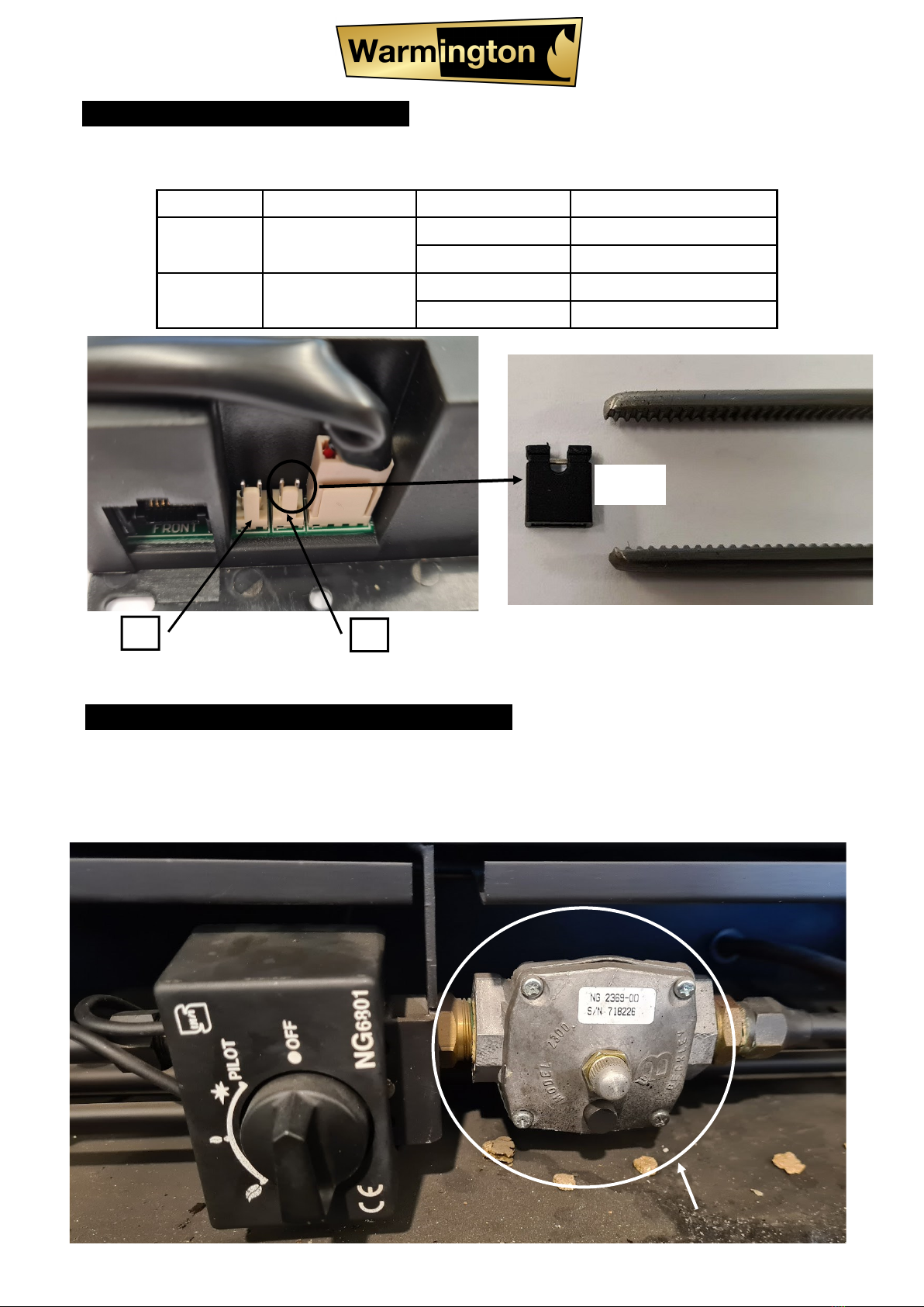
4.1 EG CONTROL BOX ADJUSTMENT
The black Millennium control box gas has a jumper to differentiate between NG and LPG, see below for
the different jumper settings:
Connector Description Jumper Selection
J6 Gas Select ON NG
OFF LPG
J8 Mode Select ON Power Flue ONLY
OFF Regular Flue System
J8 J6
NOTE: The jumper is small and can be tricky to put in or take out, best tool to use is tweezers. Take care
not to lose the jumper as it is small and can be hard to recover if lost.
Jumper
5.1 NG REGULATOR FOR SG (MANUAL) FIRES ONLY
All manual NG gas burners come installed with a regulator that sits on the inlet of the manual ignitor. If the
fire is converted from NG to LPG this needs to be removed. If the fire is converted from LPG to NG this
needs to be installed. Regulator will be supplied by Warmington and removal or installation of one has to
be done by a certified gas fitters, as the plumbing of the gas fire will have to be changed. Check for leaks
after the swap has been completed. See below for correct installation of regulator.
NG REGULATOR
Other manuals for SG-EG 600
1
This manual suits for next models
5
Table of contents
Popular Network Hardware manuals by other brands

Matrix Switch Corporation
Matrix Switch Corporation MSC-HD161DEL product manual

B&B Electronics
B&B Electronics ZXT9-IO-222R2 product manual

Yudor
Yudor YDS-16 user manual

D-Link
D-Link ShareCenter DNS-320L datasheet

Samsung
Samsung ES1642dc Hardware user manual

Honeywell Home
Honeywell Home LTEM-PV Installation and setup guide


