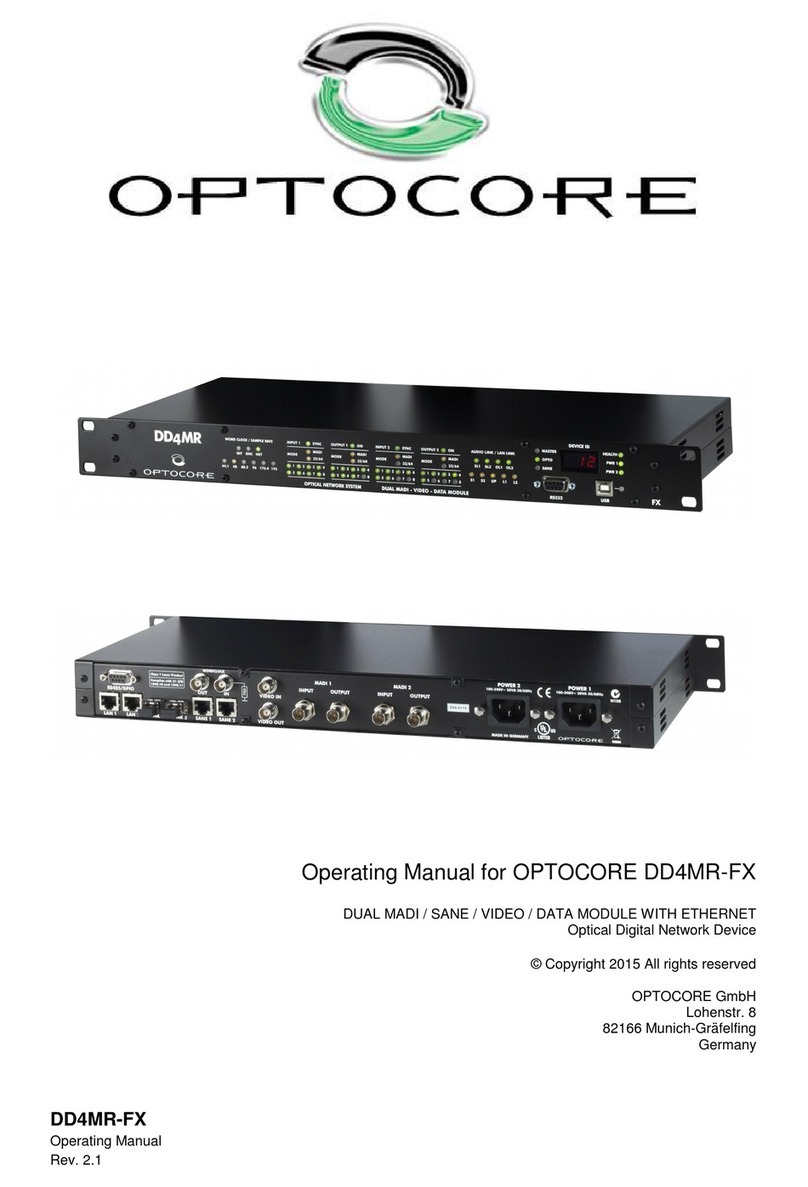
Optocore SANE TP Series User manual

SANE with Optocore - Quick Start Guide
Rev. 2.21.024
SANE with Optocore - Quick Start Guide
Using SANE TP devices as expanders for Optocore FX devices
Rev. 2.21.024
© Copyright 2020 All rights reserved
OPTOCORE GmbH
Alte Allee 28
81245 Munich
Germany

Page intentionally left blank.

SANE with Optocore 3 / 10 rev. 2.21.024
This document is intended to be a brief introduction on how to use Optocore SANE TP devices to expand the
number of inputs and outputs on Optocore FX devices.The document assumes that an Optocore system has
been configured according to the Optocore Quick Start guide and/or the Optocore Software Manual.
SANE expander setup
Optocore SANE TP network devices can be used to expand the number of inputs and outputs on Optocore FX
devices.
Configuration of SANE TP expanders is set in the Software Local Settings of the Optocore FX device and the
Local Settings of the SANE TP device.
1) Open the system Configuration window (Drop down menu: “Set” -> “Configuration”)
2) Enter the Software Local Settings of the Optocore FX device (Local Settings Column -> “Setup” button)
3) Set the TP device type for TP-ID 2-8 (TP-IDs 5-8 when
configuring DD32R-FX) as required.
By default the AES/EBU ports on TP devices are disabled.
a) To enable AES/EBU Port A on a TP device
•Configure the first TP-ID that follows the TP device
requiring an active AES/EBU port as “Generic”
•Select the required “I/O Configuration” for AES/EBU port A
b) To enable AES/EBU Port B on a TP device
•Configure the TP-ID that follows AES/EBU port A as
“Generic”
•Select the required “I/O Configuration” for AES/EBU port B
4) Click “OK” and in the “Configuration” window click “OK & Write”
5) Connect to the Optocore FX device with a USB, Ethernet or RS232 cable and “Write” the Local Settings
to the device
6) Connect to the SANE TP device with a USB, Ethernet or RS232 cable.
7) Enter the Local Settings of the SANE TP device (Drop down menu: “Set” -> “Local Settings”)
8) Set the “ID” to match the Sane port “TP-ID” configured in
the Optocore FX device’s Software Local Settings
9) Set the “Parent ID” to the ID of the Optocore FX device that
is connected to the SANE TP device
10) If utilising the AES/EBU port(s) of the SANE TP device,
configure the AES port “I/O Configuration” to match the
setup in the Optocore FX device.
11) Write the Local Settings to the SANE TP device.
12) Connect the SANE link from the Optocore FX device’s
SANE 1 port to SANE TP device’s SANE 2.
13) Connect the SANE link from SANE 1 to SANE 2 trough all devices.
Do not connect the SANE link back to the Optocore FX device.
Example:
The screenshot shows X6R-TP-16MI SANE device with TP-ID 2 configured to have both
AES/EBU port A and B enabled for a total of 8 AES inputs and 24 AES outputs.
The next SANE TP device is assigned to TP-ID 5.
FX unit - Local Settings – Sane Setup
TP ID 2 - Local Settings

SANE with Optocore 4 / 10 rev. 2.21.024
Audio is routed using the Optocore Control Software as in a regular Optocore network. Individual SANE TP
devices and converters are nested together as ports under the parent Optocore device in the device tree and the
Matrix window. The port number relate to the TP-ID of the SANE device.
Please note:
The software needs to be configured to connect to the devices using USB, Ethernet or
RS232.
In the “Administration” pull down menu, select “Server Options” to set the connection
method.
Refer to the Optocore Software Manual for setup of the Ethernet connection
Please note:
When configuring DD32R-FX with TP devices connected by SANE, IDs 1-4 are
reserved to the AES ports of DD32R-FX. The first TP-ID in the daisy chain is 5
Please note:
To access and configure Software Local Settings on an Optocore FX device:
•From the drop down menu select: “Set” -> “Configuration”
•In the Local Settings column click “Setup” for the device to be configured
•Configure as needed
•Click “OK” - In the Configuration window click “OK & Write”
•The computer must be connected to the Optocore FX with USB, Ethernet or RS232
•Locate the device from the device list and click “Write”
To access and configure Local Settings on a SANE TP device:
•The computer must be connected to the SANE TP with USB, Ethernet or RS232
•From the drop down menu select: “Set” -> “Local Settings”
•Configure as needed
•Click “Write”
Please note:
Audio inputs from SANE TP units connected to an Optocore FX device need to be
added to the total input count from the Optocore FX device in the “Configuration”
window to be accessible on the Optocore network.
The sum of all input channels in SANE sub-network cannot exceed 64 (including FX
device channels).
The sum of all output channels in SANE sub-network cannot exceed 64 (including FX
device channels).
Please note:
Do not connect a SANE link from the last device back to the Optocore FX device.
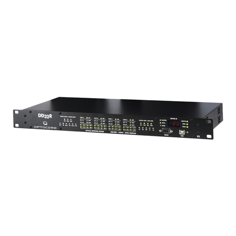
The SANE expansion is wired as a daisy chain

SANE with Optocore 5 / 10 rev. 2.21.024
EXAMPLES
The following examples demonstrate how to configure and wire Optocore SANE TP expanders when used with
Optocore FX devices.
EXAMPLE 1: TP devices without AES ports
Seven X6R-TP SANE devices are connected to an Optocore X6R-FX device as shown in the diagram below.
This system would be configured as shown below:
1) In ID16 - Software Local Settings - Sane setup:
a. TP – ID 2: X6R-16MicIn
b. TP – ID 3: X6R-8DualMic
c. TP – ID 4: X6R-8MicIn/8LineOut
d. TP – ID 5: X6R-8MicIn/8LineOut
e. TP – ID 6: X6R-16LineOut
f. TP – ID 7: X6R-16LineOut
g. TP – ID 8: X6R-16LineOut
2) For each X6R-TP – Local Settings:
a. ID: 2…8 (depending on the position of the device in the daisy-chain)
b. Parent ID: 16
c. AES port A and B: Disabled
The screenshots show Local Settings on X6R-TP-16MI (TP-ID 2) and X6R-TP-8MI/8LO (TP-ID 5).
FX unit - Local Settings – Sane Setup
TP-ID&2&
TP-ID&5&

SANE with Optocore 6 / 10 rev. 2.21.024
EXAMPLE 2: Five TP devices, one with two AES/EBU ports enabled
An Optocore X6R-FX is connected to five X6R-TP devices by SANE. The third TP device in the daisy chain is
configured with both AES/EBU ports enabled and connected to generic 3rd party converters as shown below.
This system would be configured as shown below:
1) In ID8 - Software Local Settings - Sane setup:
a. TP – ID 2: X6R-8MicIn/8LineIn
b. TP – ID 3: X6R-8DualMic
c. TP – ID 4: X6R-16MicIn
d. TP – ID 5: Generic, 8/8 Standard
e. TP – ID 6: Generic, 16 Out
f. TP – ID 7: X6R-16LineOut
g. TP – ID 8: X6R-16LineOut
2) In the third X6R-TP – Local Settings:
a. ID: 4
b. Parent ID: 8
c. AES port A: Generic, 8/8 Standard
d. AES port B: Generic, 16 Out
3) In the first, second, fourth and fifth X6R-TP– Local Settings
a. ID: 2, 3, 7, 8 (depending on the position of the
device in the daisy-chain)
b. Parent ID: 16
c. AES port A and B: Disabled
TP-ID&4&
TP-ID&2&
FX unit - Local Settings – Sane Setup
TP devices - Local Settings

SANE with Optocore 7 / 10 rev. 2.21.024
EXAMPLE 3: Two TP devices connected to DD4MR-FX, each with a single AES/EBU port enabled
In this example a DD4MR-FX Optocore unit is connected to two X6R-TP devices, each with one AES port
enabled.
This system would be configured as shown below:
1) In ID22 - Software Local Settings - Sane setup:
a. TP – ID 2: X6R-16MicIn
b. TP – ID 3: Generic, 16 Out
c. TP – ID 4: X6R-8MicIn/8LineOut
d. TP – ID 5: Generic, 16 In
2) In X6R-TP-16MI - Local Settings:
a. ID: 2
b. Parent ID: 22
c. AES port A: Generic, 16 Out
d. AES port B: Disabled
3) In X6R-TP-8MI/8LO - Local Settings:
a. ID: 4
b. Parent ID: 22
c. AES port A: Generic, 16 In
d. AES port B: Disabled
FX unit - Local Settings – Sane Setup
TP ID 2 - Local Settings
TP ID 4 - Local Settings

SANE with Optocore 8 / 10 rev. 2.21.024
EXAMPLE 4: Two TP devices connected to DD2FR-FX and three Y3R-TP cards connected through SANE2
In this example a DD2FR-FX Optocore unit is connected to two X6R-TP devices and three Yamaha expansion
cards connected through SANE2 connector compatible with MADI over CAT protocol. Depending on number of
cards channel count for MADI Cat 2, should match number of cards x 16. E.g. for 2 cards 32 In and 32 Out should
be configured.
This system would be configured as shown below:
1) In ID4 - Software Local Settings - Sane setup:
a. TP – ID 2: X6R-16MicIn
b. TP – ID 4: X6R-8MicIn/8LineOut
c. MADI Cat 2 IN – AES10-2003 48 ch
d. MADI Cat 2 OUT – AES10-2003 48 ch
2) In X6R-TP-16MI - Local Settings:
a. ID: 2
b. Parent ID: 4
c. AES port A: Disabled
d. AES port B: Disabled
3) In X6R-TP-8MI/8LO - Local Settings:
a. ID: 3
b. Parent ID: 4
c. AES port A: Disabled
d. AES port B: Disabled
FX unit - Local Settings – Sane Setup

SANE with Optocore 9 / 10 rev. 2.21.024
EXAMPLE 5: Two TP devices connected one with AES/EBU generic device expansion to DD2FR-FX and
two additional Y3R-TP cards
In this example a DD2FR-FX Optocore unit is connected to two X6R-TP devices, where one is expanded with
external AES/EBUI converter and two Yamaha expansion cards connected to SANE daisy chain. Depending on
number of cards channel count for MADI Cat 2, should match number of cards x 16. E.g. for 2 cards 32 In and 32
Out should be configured (sum for TP ID5 – ID8 is 32/32 channels)
This system would be configured as shown below:
4) In ID2 - Software Local Settings - Sane setup:
e. TP – ID 2: X6R-16MicIn
f. TP – ID 3: X6R-16LineOut
g. TP – ID 4: Generic, 16 In
h. TP – ID 5: Generic, 8/8 Standard
i. TP – ID 6: Generic, 8/8 Standard
j. TP – ID 7: Generic, 16 In
k. TP – ID 8: Generic, 16 Out
5) In X6R-TP-16MI - Local Settings:
e. ID: 2
f. Parent ID: 2
g. AES port A: Disabled
h. AES port B: Disabled
6) In X6R-TP-16LO - Local Settings:
e. ID: 3
f. Parent ID: 2
g. AES port A: Generic ,16 in
h. AES port B: Disabled
FX unit - Local Settings – Port Setup

SANE with Optocore 10 / 10 rev. 2.21.024
Contact Information
Mailing Address:
OPTOCORE GmbH
Alte Allee 28
D-81245 Munich
Germany
Telephone:
+49 – (0)89 – 8999640
Facsimile:
+49 – (0)89 – 89996455
Internet:
www.optocore.com
Email:
This manual suits for next models
5
Table of contents
Other Optocore Network Hardware manuals