Table of Contents
Overview ......................................................................................................................................................................... 1
Requirement.................................................................................................................................................................. 1
Scope .......................................................................................................................................................................... 1
Hardware Information ....................................................................................................................................................... 1
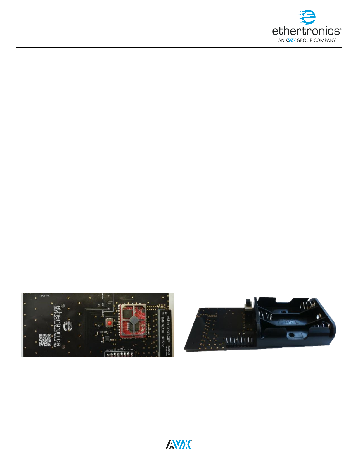
Evaluation Board............................................................................................................................................................. 1
Passive Evaluation Board .............................................................................................................................................. 1
Active Evaluation Board ................................................................................................................................................ 2
USB UART Cable ............................................................................................................................................................. 3
Computer with Windows OS ............................................................................................................................................... 4
Connection.................................................................................................................................................................... 4
Passive Evaluation Board Connection ............................................................................................................................... 4
Active Evaluation Board Connection ................................................................................................................................. 5
Software Information ........................................................................................................................................................ 5
Installation ...................................................................................................................................................................... 5
Installing the Driver.......................................................................................................................................................... 5
Installing the Ethertronics Control Tool.................................................................................................................................. 6
Quick Start Guide ............................................................................................................................................................. 7
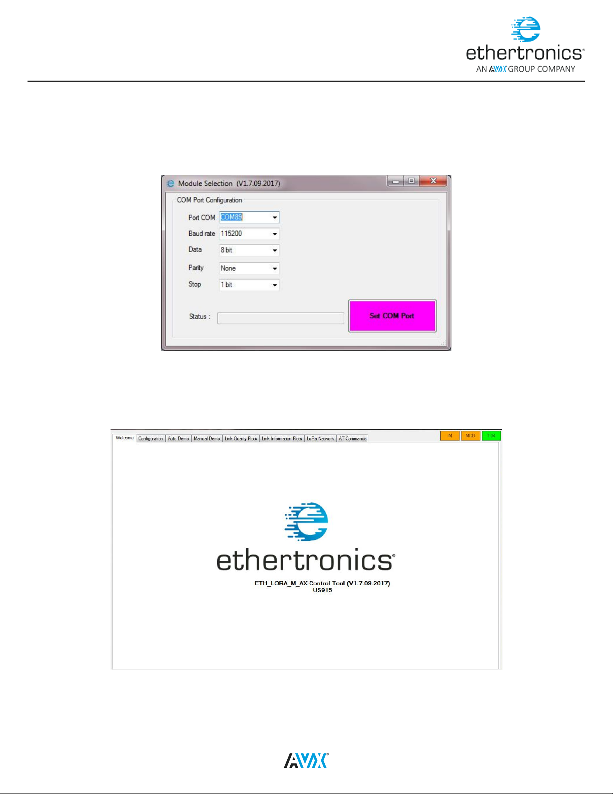
Ethertronics control Tool ................................................................................................................................................... 7
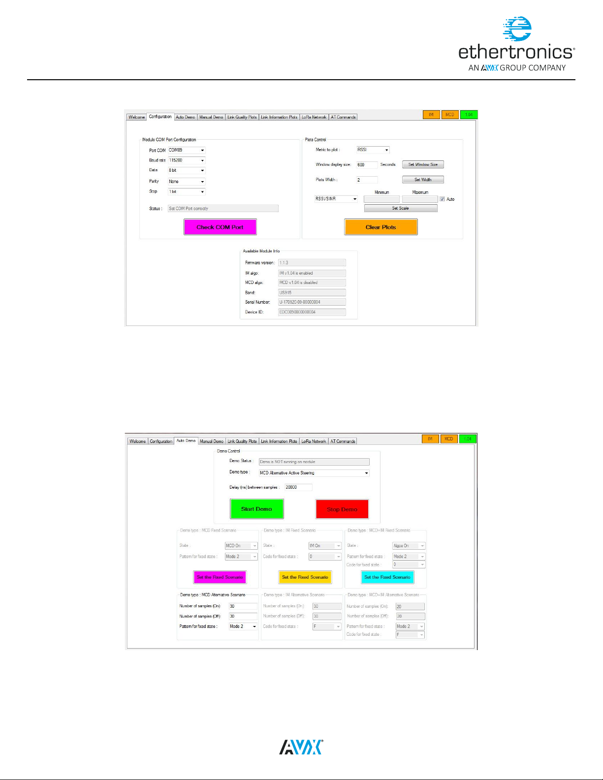
Conguration Tab ....................................................................................................................................................... 8
Auto Demo Tab .......................................................................................................................................................... 8
Manual Demo Tab ....................................................................................................................................................... 9
Link Quality Tab.......................................................................................................................................................... 9
Link Information Tab.................................................................................................................................................. 10
LoRa Network Tab..................................................................................................................................................... 10
AT Commands Tab .................................................................................................................................................... 11
Tera Term................................................................................................................................................................... 11