manuals.online logo
Brands
  1. Home
  2. •
  3. Brands
  4. •
  5. AVZ
  6. •
  7. Tent
  8. •
  9. AVZ Cubola Solidare User manual

AVZ Cubola Solidare User manual

Cubola®Solidare®EN 20-04-2018
Manufacturing and installation instruction
Cubola® Solidare®
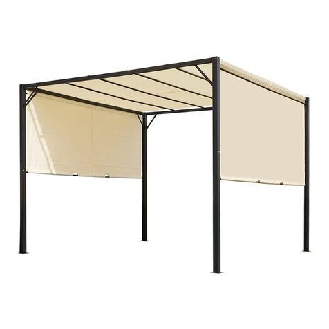
Free standing awning/pergola awning
Cubola®Solidare®EN 20-04-2018 2
* * A T T E N T I O N * *
AVZ accepts no liability for any errors in this manual,
or for any damage or losses resulting from the use thereof.
Cubola®Solidare®EN 20-04-2018 3
General information Cubola®Solidare®
Maximum dimensions (cm)*
Width unit
Projection unit
Height unit
Maximum per unit
600 cm
400 cm
300 cm
* = While the system in theory allows for endless connection in all directions, it is not possible to end both front
profiles at one profile.
Note: No joints are available for the fabric rollers, so each unit of max. 6000 x 4000 mm has 2 motors.
Fabric confection
The Solidare is only available with acrylic fabric in panels. Without zipper, Soltis fabric is also available.
The fabric of the Solidare is wound bottom wise.
The fabric in the front support beam is wound topwise (max. 800 mm projection).
Motor diagram
Width
Projection
150 to 300 cm
300 to 350 cm
351 to 400 cm
From 200 to 300 cm
40 Nm
40 Nm
From 301 to 400 cm
40 Nm
40 Nm
50 Nm
From 401 to 500 cm
40 Nm
40 Nm
50 Nm
From 501 to 600 cm
50 Nm
50 Nm
50 Nm
For the fabric in the support beam (valance) use at least 20Nm without fabric stretch compensation or
40Nm with fabric stretch compensation.
Mounting brackets
The number of mounting brackets depends on the width of the Cubola i.c.w. Solidare.
Width
Freestanding
Wall-mounted
200 to 400 cm
Set L+R freestanding
(4217420-…)
Set L+R wall-mounted (4217424-…)
400 to 500 cm
Set L+R freestanding (4217420-…)
1x centre (4217422-…)
Set L+R wall-mounted (4217424-…)
1x centre wall-mounted (4217426-…)
500 to 600 cm
Set L+R freestanding (4217420-…)
2x centre freestanding (4217422-…)
Set L+R wall-mounted (4217424-…)
2x centre wall-mounted (4217426-…)
Cubola®Solidare®EN 20-04-2018 4
General information Cubola®Solidare®
Determine the centre-to-centre size per unit
In order to determine the cut sizes, first measure the centre to centre size of each unit. A drawing with dimensions is
shown below.
For a more detailed view, see the cut size diagram and the enclosed cut lists.
Note: Mounting plates extend beyond the width and projection sizes. This is 5 mm for the wall mounting plate and
45 mm for the mounting plate of the post.
Dissimilar units
Note: In case of a connected system with dissimilar units placed in front or alongside one another, the outer size
minus the values stated above are divided over the number of units.
For example: Freestanding model with 2 units connected in width:
Total width = 10000 mm
The total CTC size is then 10000 –110 mm = 9890 mm
If the first unit has a CTC size of 3000 mm, the second unit will be 6890 –3000 = 3890 mm.
Cut sizes
The cut sizes apply to all configurations, including a connected or wall-mounted system. It is based on the CTC size
of each unit. The applicable sizes are listed in the cut size diagram shown on the following page.
Diepte
HOH diepte = Diepte –110 mm
Diepte
HOH diepte = Diepte –10 mm
Hart tot wand = HOH diepte –45
Breedte (excl. montageplaten)
HOH breedte totaal = Breedte totaal –110 mm
HOH breedte 1
HOH breedte 2
Depth
Depth
CTC depth –depth -110 mm
CTC projection = projection - 10 mm
C to wall = HOH projection –45
Width (excl. sketch plates)
Total CTC width = width - 110 mm
CTC width 1
CTC width 2
Depth = CTC depth + 110 mm
CTC projection = depth - 110 mm
Supporting beam projection = CTC projection - 110 mm
CTC Width
Height
Post = height –10 mm
Height above ground level
Depth below ground level
Ground level
Fabric projection=
CTC projection - 110 mm
Guide =
CTC projection - 345 mm
CTC width = width + 110 mm
Supporting beam/beam front = CTC width - 110 mm
Bottom cover = CTC width - 152 mm
Top cover/top cover extension = CTC width - 153 mm
Roller = CTC width –195 mm
Fabric in cassette = CTC width - 252 mm
Front profile = CTC width - 324 mm
Front profile cover = CTC width - 325 mm
Fabric in supporting beam = CTC width - 190 mm
Roller 63 = CTC width - 192 mm
Front profile = CTC width –135 mm
Cubola®Solidare®EN 20-04-2018 5
General information Cubola®Solidare®
Freestanding (connected)
Wall-mounted ( connected )
Single
freestanding
Double
freestanding
side-by-side
Double
freestanding
following
Single wall-
mounted
Double wall-
mounted side-
by-side
Double wall-
mounted
following
CTC projection per unit
Projection –110 mm / no. of units
Projection –10 mm / no. of units
CTC width per unit
Width –110 mm / no. of units
Cut sizes Width
No. of pieces
Width support
beam
CTC width
–110 mm
1
2
1
0
0
0
Front support
beam
CTC width
–110 mm
1
2
2
1
2
2
Mounting part
front
CTC width
–116 mm
1
2
2
1
2
2
Front profile
CTC width
–135 mm
1
2
2
1
2
2
Roller 85
Somfy/ASA
CTC width
–195mm/ -198mm
1
2
2
1
2
2
Roller 63
Somfy/ASA
CTC width
–160 / –175 mm
1
2
2
1
2
2
Cover front
profile
CTC width
–325 mm
1
2
2
1
2
2
Front profile
CTC width
–324 mm
1
2
2
1
2
2
Tensioning
wire
Front profile
–160 mm
1
2
2
1
2
2
Cover profile
Front profile
–274 mm
1
2
2
1
2
2
Bottom cover
CTC width
–152 mm
1
2
2
1
2
2
Top cover
CTC width
–153 mm
1
2
2
1
2
2
Cover extension
CTC width
–153 mm
(1)
(2)
(2)
(1)
(2)
(2)
Cut sizes Projection
No. of pieces
Beam
projection
CTC projection
–110 mm
2
3
4
2
3
4
Guide
CTC projection
–345 mm
2
4
4
2
4
4
Gutter profile
(optional)
CTC projection
–250 mm
(2)
(4)
(4)
(2)
(4)
(4)
PVC guide
CTC projection
–320 mm
2
4
4
2
4
4
Number and cut sizes
The cut sizes apply to all
configurations, based on the CTC
size of each unit. The number of
units to be used is stated in the
table below.(Various cut sizes are
enclosed)..
Cubola®Solidare®EN 20-04-2018 6
General information Cubola®Solidare®
Note: -You must determine the numbers of pieces for other configurations yourself.
- Use of dissimilar units will lead to different CTC sizes; this will result in multiple
lengths for one type of profile!
Cut sizes Height
No. of pieces
Leg
Height + size under
ground level –10
mm
4
6
6
2
3
4
Fabric dimension
No. of pieces
Fabric with
zipper in
cassette
CTC width
–252 mm
1
2
2
1
2
2
CTC projection
+ 0 mm
Fabric without
zipper in
cassette
CTC width
–314 mm
1
2
2
1
2
2
CTC projection
+ 0 mm
Fabric in
beam
CTC width
-190 mm
1
2
2
1
2
2
Fixed height size =
800 mm
2 Fabrics in
beam
(system larger
than 4.0 m)
CTC width
–250 mm / 2
2
4
4
2
4
4
Fixed height size =
800 mm
Cubola®Solidare®EN 20-04-2018 7
Assembly Cubola®Solidare®
Sub-composition support beams
1. Cut the profiles to the correct lengths according to the cut lists.
2. Place the drilling template and drill 4 holes according to the ‘support beam pattern. Do the same on
the other side of the profile.
Freestanding Cubola®Solidare®
3. Insert the corner mounting piece in the leg. Note: Turn the side with the most holes towards the centre
of the profile so that the corner mounting piece is laid 2 mm into the leg. Note: When the profile is
turned around, the corner mounting piece will be flush with the profile. This is used for wall mounting
and thus not desired for this application!.
4. Fasten the corner mounting pieces with the bolts on the top.
Cubola®Solidare®EN 20-04-2018 8
Assembly Cubola®Solidare®
Wall mounting Cubola®Solidare®
5. Screw the wall mounting plate to the mounting profile.
Note: Side mounting plate with holes at 50 mm (side with the most holes) against the wall mounting
plate.
6. Slide the mounting profile into the tubular profile and temporarily fasten or deliver the support
separately with the profile.
On site, first mount the mounting profile to the wall before attaching the support beam.
Note: The wall mounting plate is available in a left and right version.
7. On the other side, place the mounting profile (corner profile) in the support beam and fasten it with
bolts. Note: Turn the side with the most holes towards the centre of the profile so that the mounting
piece is laid 2 mm into the support beam. Note: When the profile is turned around, the corner
mounting piece will be flush with the profile.
Cubola®Solidare®EN 20-04-2018 9
Assembly Cubola®Solidare®
Sub-composition support beam front side
1. Shorten the front profile support beam, mounting profile and front profile to the correct lengths.
2. Place the drilling template on the top of the profile and drill 4 holes according to the ‘support beam’
pattern. Do the same on the other side of the profile
3. Drill on both sides of the mounting profile 4 holes of 6.5 mm, as shown hereunder.
Tap M8 thread in the holes and also in the holes on the side.
4. Place the PVC slide bearing between the fabrics (fasten it later in the mounting profile with self-drilling
screws). Insert PVC inserts into the fabric and wind the fabric top wise around the fabric roller. Make
sure that the groove on the pull side is filed round so that the fabric is not torn by being pulled against
the sharp edge.
5. Insert bearing bung into the non-operating side of the fabric roller.
6. Place the motor with friction ring and motor bung into the other side of the roller. Take the direction
of rotation into account.
7. Place the complete fabric roller into the mounting profile.
8. Mount the end plate with bearing pin and the end plate with motor bracket to the mounting profile.
Make sure the motor cable is drawn through the cable opening into the end plate. Fasten the PVC
central slide bearing to the mounting profile with self-drilling screw 3,5x9,5.
Cubola®Solidare®EN 20-04-2018 10
Assembly Cubola®Solidare®
9. Slide the complete mounting profile in the support beam front side and fasten both sides on the top
with 8 bolts.
10. Slide the sealing strip into the support beam.
11. Slide the filed off fabric roller onto the fabric and wind the fabric eventually.
Cubola®Solidare®EN 20-04-2018 11
Assembly Cubola®Solidare®
Sub-composition legs
1. Shorten the legs to the correct size.
2. Place the drilling template on the profile and drill 7 holes according to the 'top of leg’ pattern.
3. Drill the centred hole up to 20 mm. This hole is for the cable entry.
4. Turn the profile 90° (quarter turn) and drill the same pattern again. If the leg is fitted with support
beams on 3 sides (in case of a connected system), the pattern must also be drilled on the third side.
5. Place the drilling template against the bottom of the profile and drill according to the bottom of leg
pattern.
6. Also drill two holes on the other side. Preferably drill the holes on the same side as the holes on the
top of the profile.
7. Fasten the mounting adjusting plate to the mounting profile using countersunk bolts.
8. Place the leg on the profile and fasten the 4 bolts on the side. You can opt to first fasten the adjusting
plates to the mounting location against the wall before placing the profile on it.
9. Insert the mounting part leg into the top of the profile
10. Temporarily fasten the mounting profile using 2 bolts and nuts or loosely fit the adjusting plate
mounting profile into the leg.
11. Loosely fit the cover plates, bolts and screws into the leg or fasten them temporarily
Cubola®Solidare®EN 20-04-2018 12
Assembly Cubola®Solidare®
Sub-composition side guides
1. Shorten the side guides to the correct lengths.
2. Place the end cap front profile at the mounting position, make sure the front is flush with the end of
the side guide. Drill a hole of 6,5 mm through the hole in the end cap.
3. Drill 2 holes of 7 mm, as shown below, to assemble the support beam to the top cover support.
4. Stick each 400-500 mm 2x neoprene self-adhesive neoprene strips on the guides. Stick at the
bottom and 100 mm from the top a neoprene strip.
5. Fasten the funnel side guide to the guides.
6. Slide the PVC side guide in the side guide and install the guide plate.
Cubola®Solidare®EN 20-04-2018 13
Assembly Cubola®Solidare®
7. Slide the end bearing block with bearing in front of the guide.
8. Place the end cap of the front profile around the guide and fasten it on the side with a countersunk
screw (through the guide into the end bearing block).
9. Place a clamping plate into the bottom of the profile and fasten the end cap on the bottom.
10. On the top of the profile turn a self-drilling screw. This ensures that the end is fastened
on all sides.
Sub-composition gutter guides (optional)
1. Shorten the 2 parts of the gutter to the correct lengths.
2. Cut the ridge at 100 mm from the front side and 112 mm from the back side until the
rejuvenations. Note: Left and right version.
3. Watch out not to damage the edges of the profile, the saw-blade is very close!
A. Always use this part. Also in combination with a side cap (e.g. SolidScreen) for instance.
B. If no side cap is used, use this part to close off the space between the support beam and the guide.
4. Break the cut parts of the profile by using pincers.
5. Place the end cap gutter at both ends of the profile and fasten them.
6. Drill 2 holes of 4.5 mm at intervals of ± 500 mm above one another on the drill lines in the profiles
for fitting to the guide. Then fasten the two profiles into the side guide using self-drilling screws.
A.
B.
Cubola®Solidare®EN 20-04-2018 14
Assembly Cubola®Solidare®
Sub-composition tensioning system (systems larger than 4.0 meter)
1. Slide the clamping plate in the slot of the front profile with the wholes to the centre of the front
profile. Make sure the sides of the clamping plate and the front profile are flush.
2. Mark the holes and drill hole of 9 mm. Do this on both sides of the front profile. Note: Do not drill
the holes of the clamping plate.
3. Drill holes of 6,5 mm with aid of the drilling template in the slot of the front profile. Keep about 500
mm distance between the holes. Keep a distance of 700 mm in the middle of the front profile. Note:
The distance of 700 mm is the required space for the clamp cleat during opening and closing.
4. Slide the block to the centre of the tailored tensioning wire and screw it into place with the hexagon
screw.
ATTENTION: Slide first the spring
support blocks in the front profile.
See item 8 –9 page 17.
Cubola®Solidare®EN 20-04-2018 15
5. Take the tensioning wire through the tensioning wire mounting blocks and the cover profile. Fasten
the tensioning wire mounting blocks in the clamping plate with M8x25 bolts. Note: Make sure the
mounting blocks are centered under the front profile.
6. Keep at both sides of the mounting block and the cover profile a distance of 2 mm. Fasten the cover
profile through the holes of 6,5 mm.
7. Fasten the hexagon connection nut with a washer to the side of the tensioning wire with screw-
thread. On the other side the clamping sleeve with wedge set is positioned.
8. Turn the hexagon connection nut tight to tension the front profile straight.
Cubola®Solidare®EN 20-04-2018 16
9. Close both sides of the tensioning system with covers and fasten with M4x25 cylinder screws.
Sub-composition cassette with front profile
1. At the operation side drill a hole of 11 mm in the bottom cover for the passage of the motor cable.
Make a rushing in the hole.
2. Slide the mounting plates of the mounting brackets and the PVC inlay strip in the bottom cover. Screw
the top cover supports on the bottom cover with plate screws 4,2x32 mm. Fasten the aluminium
motor bracket and the PVC bearing block on the top cover supports.
3. Slide the 2 fabric strings into the fabric.
4. Roll the fabric bottom wise onto the roller.
5. Install the cord pulleys.
Cubola®Solidare®EN 20-04-2018 17
6. At the operation side, install the motor in the fabric roller and the bearing bung at the bearing side.
7. Make 4 windings of cord around the cord pulley and ensure that the cord runs neatly. TIP: Apply double
sided tape in the cord pulley before winding the cord. Now the first 4 windings are fixed in place and
will remain so during transport. The required length of cord per side is determined as follows: 2x the
projection + 1.5x the width + 1 meter.
8. Slide the front profile onto the fabric. Place the 4 support blocks in the front profile. Attach the guide
blocks to the front profile using self-tapping screw 4,2x45 mm. Fasten the plastic end caps for the
zipper fabric with self-tapping screw 3,5x32 mm.
9. Place the zipper parallel to the PVC end cap and make sure the zipper oversizes about 7 mm on both
sides. Fasten the PVC end plate with plate screw 3,5x16 mm.
10. Hook the spring to the eye onto the guide block. Slide the support blocks over the springs and fasten
with self-drilling screws 4,2x13 mm (2 pcs. per spring.
Cubola®Solidare®EN 20-04-2018 18
11. Apply the stickers showing maximum stretch of the spring in the front profile. A spring may be
stretched up to 60% of its original length.
In case of a short spring (length 35 cm), apply the redline of the sticker at 56 cm from the side of the
front profile.
In case of a long spring (length 57 cm), apply the redline of the sticker at 91 cm from the side of the
front profile.
12. Pass the cord through the guide block in the front profile. Allow a loop to extend from the front profile.
Neatly roll up the rest of the cord and lay it into the front profile.
13. Disassemble the top part of the aluminium motor support and the bearing block. Place the complete
internal mechanism with front profile into the bottom cover. Fasten the entire core with the top part
of the motor bracket and the bearing block.
Cubola®Solidare®EN 20-04-2018 19
14. Control the cord pulleys are straight in front of the wheel on the top cover support. The cord rolls
bottom wise.
15. Install the mounting brackets on the bottom cover. The number of the mounting brackets depend on
the width of the system (see page 3). Place the outer mounting brackets against the top cover
support. Divide the central brackets over the length of the cassette.
16. Use the mounting brackets below.
17. Install the top cover on the cassette and fasten it with self-drilling screws 4,2x13 mm. Click the
cover profile front profile on the front profile. The cassette is ready for transport.
Free-standing
Wall-mounted
Cubola®Solidare®EN 20-04-2018 20
Installation Cubola®Solidare®
Installation free-standing Cubola®Solidare®
1. Measure the positions of the legs on the floor. Various means of floor mounting are possible,
depending on the situation. For example: on concrete pads, foundation or existing floor. Mounting on
concrete pads is assumed for the purposes of these instructions
2. Dig 4 holes and place 4 concrete pads. Place these at the right height, taking the ground level and
adjusting option on the concrete pad into account.
3. Fasten 2 legs to the support beam. This forms the side (motor-side) of the Cubola through which the
cables are fed.
4. Ensure that a control cable for the valance system is fed through the beam.
5. Connect a control plug to the cable at the front of the system.
6. At cassette side, fasten a control plug to the motor cable. Connect the control plug and let it drop into
the leg.
7. From the base plate leg, pass a (floor)cable, which is connected to the network until the top of the
electrical box.
8. Fasten wall mounting beams to the 2 concrete bases, ensure that the (floor)cable below is free (adjust
the adjusting plate at small height above the concrete base). Install the arch levelled onto the 2
concrete bases.
9. Assemble a corner from the support beam and the leg. No wiring is conducted here. Place this corner
on the next concrete base and connect it to the installed arch. This is the rear beam of the system.
10. Make the next corner and install it on the next concrete base and connect it to the installed corner.
This will be the non-operating side. Do not yet fasten the leg on concrete base.
11. Place the front support beam between the opening.
12. Feed the motor cable through the hole in the leg.
13. Fasten the front support beam with the M8x35 bolts.
14. Fasten a control plug to the motor cable. Connect the control plug and let it drop into the leg.
15. Measure the system diagonally, move the concrete pads if necessary to achieve the perfect position.
Also set the exact height of the adjusting plate.
16. Fasten the adjusting plate to the concrete base.
17. Place covers on the legs, let the leg with control plug and floor cable open, so the cassette can be
connected.
18. Remove the 2 bolts from the top of the support beams on which the cassette will be placed. Place the
cassette on the support beams and fasten using the 2 removed inner bolts

Popular Tent manuals by other brands

Woods EASY UP 076-3242-6 quick start guide

Woods

Woods EASY UP 076-3242-6 quick start guide

UBERHAUS DESIGN 999-3142990 manual

UBERHAUS DESIGN

UBERHAUS DESIGN 999-3142990 manual

Exped VELA I EXTREME instructions

Exped

Exped VELA I EXTREME instructions

Fit4Home LMLC-23 user manual

Fit4Home

Fit4Home LMLC-23 user manual

viparspectra Mylar Hydroponic Reflective 600D instruction manual

viparspectra

viparspectra Mylar Hydroponic Reflective 600D instruction manual

Let's Go Aero Tentris ArcHaus ARC-10 owner's manual

Let's Go Aero

Let's Go Aero Tentris ArcHaus ARC-10 owner's manual

SereneLife SLGZ10W user manual

SereneLife

SereneLife SLGZ10W user manual

Dura-Max Vinyl Owner's manual/ instructions for assembly

Dura-Max

Dura-Max Vinyl Owner's manual/ instructions for assembly

HAMPTON BAY 5RGZ1389-WBS Use and care guide

HAMPTON BAY

HAMPTON BAY 5RGZ1389-WBS Use and care guide

Beavertail Flip Top Blind instructions

Beavertail

Beavertail Flip Top Blind instructions

Aztec Tents QWIK-TOP FRAME product manual

Aztec Tents

Aztec Tents QWIK-TOP FRAME product manual

Alice's Garden DOMUS TRTDOME250 manual

Alice's Garden

Alice's Garden DOMUS TRTDOME250 manual

Bestway Inflate Your Fun Ocaso X3 owner's manual

Bestway

Bestway Inflate Your Fun Ocaso X3 owner's manual

EzyFast 19JS00121201 instruction manual

EzyFast

EzyFast 19JS00121201 instruction manual

Jula Axley 009911 operating instructions

Jula

Jula Axley 009911 operating instructions

23zero Dakota 1400 user manual

23zero

23zero Dakota 1400 user manual

Outdoor Revolution Ozone 6.0XT Instruction and Care Manual

Outdoor Revolution

Outdoor Revolution Ozone 6.0XT Instruction and Care Manual

BEGA 13 231 Instructions for use

BEGA

BEGA 13 231 Instructions for use

manuals.online logo
manuals.online logoBrands
  • About & Mission
  • Contact us
  • Privacy Policy
  • Terms and Conditions

Copyright 2025 Manuals.Online. All Rights Reserved.