Awaiba Orion USB3 User manual

ORION USB3
Evaluation Kit

Orion USB3 Evaluation Kit
Table of Contents
1 General Description..........................................................................................................................................................4
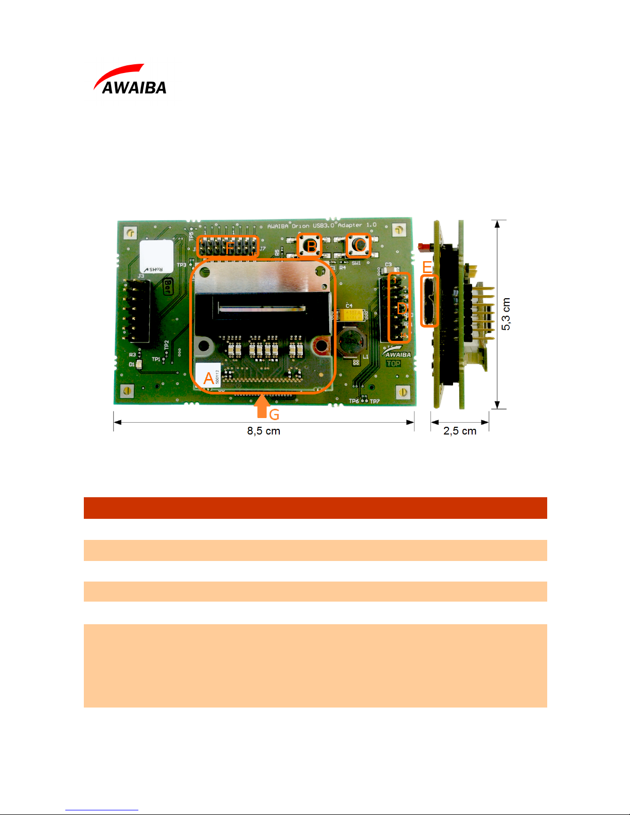
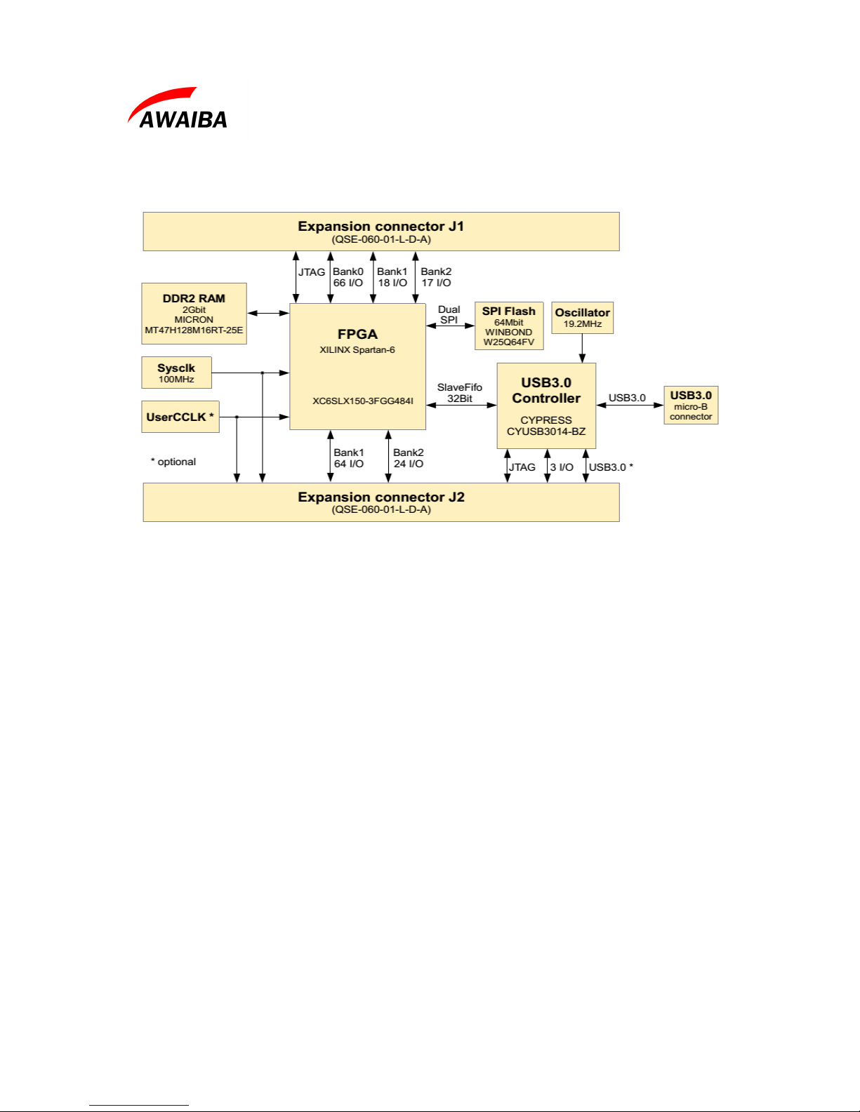
2 System Overview..............................................................................................................................................................5
3 Operating Instructions.......................................................................................................................................................7
3.1 Recommen e Equipment .........................................................................................................................................7
3.2 Resolution / Fame rate an ADC gain settings ..........................................................................................................7
3.3 Auxiliary pixel settings...............................................................................................................................................8
3.4 External Trigger Input ...............................................................................................................................................8
3.5 Test Mux Signals rea ing ..........................................................................................................................................9
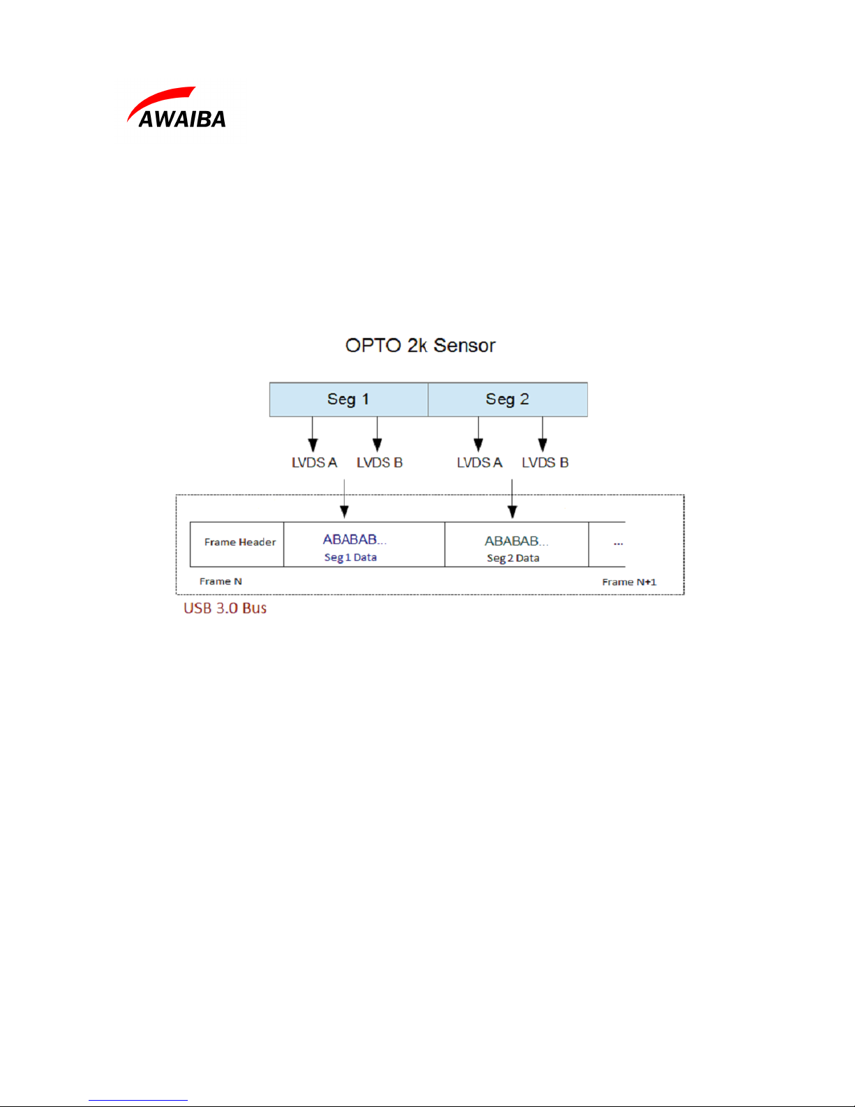
3.6 Rea out Implementation...........................................................................................................................................10
4 Evaluation Software........................................................................................................................................................11
5 Troubleshooting..............................................................................................................................................................12
5.1 How to Install Awaiba Line Viewer.........................................................................................................................12
5.2 How to Start Awaiba Line Viewer ...........................................................................................................................12
5.3 How to Use Awaiba Line Viewer ...........................................................................................................................12
5.4 How to Debug Orion USB3 boar ...........................................................................................................................12
Date: 30/03/16 Version 1.0.4 Page: 2/16

Orion USB3 Evaluation Kit
Index of Tables
Table 1: Orion interface boar ..............................................................................................................................................5
Table 2: ADC resolution configuration................................................................................................................................7
Table 3: Pixel size configuration..........................................................................................................................................8
Table 4: Hea boar pin out.................................................................................................................................................9
Index of Figures
Figure 1: Orion evaluation set overview...............................................................................................................................4
Figure 2: ORION interface boar ........................................................................................................................................5
Figure 3: FPGA – USB boar functional Diagram ..............................................................................................................6
Figure 4: OPTO Hea Boar pin out assignment................................................................................................................9
Figure 5: Orion rea out implementation.............................................................................................................................10
Figure 6: FPGA Configuration...........................................................................................................................................13
Figure 7: Orion USB3 En points list..................................................................................................................................13
Figure 8: Write to en point 0x01.......................................................................................................................................14
Figure 9: Streamer example ata from en point 0x81........................................................................................................15
Date: 30/03/16 Version 1.0.4 Page: 3/16

Orion USB3 Evaluation Kit
1 eneral Description
This ocument preten s to be a user manual to the Awaiba ORION evaluation kit . The ORION
eval kit is emonstration kit is a two-boar system use to evaluate the Awaiba ORION 1K an 2K
line CMOS image sensor. The kit consists of the CMOS image sensor an a circuit boar
containing all support circuits necessary to operate the CMOS image sensor. In a ition, the kit
inclu es software the permits for any use to acquire ata an configure the system through an USB3
interface.
Date: 30/03/16 Version 1.0.4 Page: 4/16
Figure 1: Orion evaluation set overview

Orion USB3 Evaluation Kit
2 System Overview
The evaluation kit is compose of two boar s, one off-the-shelf USB-FPGA interface an another
one specific to the Orion sensor.
Legend
A Orion sensor: 1K or 2K
B FX3 USB 3 controller reset button
C FPGA soft reset button
D JTAG connection pin: 1, 2, 4, 6, 8, 10
E USB3 plug
FGPIO: 1 - External trigger Input
2 - VCC
3 - LVAL Segment 2
6 - LVAL Segment 1
9 - MISO
11 - MOSI
13 - SCLK
15 - N_CS
G Connector to the a apter boar (Hirose DF17(4.0)-80DS-0.5V(57))
Table 1: Orion interface board
Date: 30/03/16 Version 1.0.4 Page: 5/16
Figure 2: ORION interface board

Orion USB3 Evaluation Kit
The off-the-shelf USB/FPGA boar is an embe e mo ule featuring a XILINX™ SPARTAN-6
FPGA in conjunction with the CYPRESS™ FX3 SuperSpee USB 3.0 interface controller.
Main Features:
•USB3.0 SuperSpee interface through versatile CypressTM EZ-FX3 controller
•USB bus-powere , no external power supply necessary
•Two FX3 GPIO on expansion connector
•XilinxTM Spartan-6 FPGA ( LX150)
•2Gbit DDR2 memory
•64Mbit ual SPI configuration/ ata memory
•High stability 100MHz +/-25ppm onboar clock oscillator
•512Kbit I²C EEPROM for FX3 configuration ata
•I²C interface available on expansion connector to increase available FX3 configuration
memory for stan alone applications
•FPGA configuration from SPI memory, JTAG or USB 3
•JTAG for FPGA an FX3 controller available on expansion connectors
Date: 30/03/16 Version 1.0.4 Page: 6/16
Figure 3: FPGA USB board functional Diagram

Orion USB3 Evaluation Kit
3 Operating Instructions
The kit is factory a juste an operational when receive . This section lists recommen e
equipment, basic operational instructions, inclu e signal voltage level requirements, options that
are factory selecte but that are easily mo ifie by the user.
3.1 Recommended Equipment
–Oscilloscope
–Desktop PC (recommen e )
–USB3 Port
–Signal Generator
3.2 Resolution / Fame rate and ADC gain settings
The chip has the capability of increasing the output Line Rate by re ucing the ADC resolution. For
each ADC resolution there is ifferent Gains.
For 13 bits resolution, it is possible to achieve 20KHz, with integration time efine as 40us.
Table 2 exemplifies, for instance, the recommen e ADC gain configuration for resolution 13 bits,
12 bits an 11 bits.
Resolution Frame Rate ADC time Analogue ain
Register 0x04
13 bits 20 KHz 40 us CF
12 bits 40 KHz 22 us 9F
11 bits 70 KHz 11 us 40
Table 2: ADC resolution configuration
Date: 30/03/16 Version 1.0.4 Page: 7/16

Orion USB3 Evaluation Kit
3.3 Auxiliary pixel settings
This sensor has the unique feature of have two pixel sizes option available for the user. Basically the
user can choose between a small photo io e pixel 10 um x 10 um, an larger one with 10 um x 200
um.
Reg 0x08 Reg 0x02
Large Pixel
10 um x 200 um Bit 7 = 0 CVC Gain = 1x
Bit 3 = 1
Smaller Pixel
10 um x 10 um Bit 7 = 1 CVC Gain = 11x
Bit 3 = 0
Table 3: Pixel size configuration
3.4 External Trigger Input
As an example of the signal that can be connecte to the external trigger pin, please use a pulse
generator with 970Hz an make sure that between each pulse you have 1ms.
Please change the FPGA register 0, Sensor Operation Control to 0x07.
Date: 30/03/16 Version 1.0.4 Page: 8/16

Orion USB3 Evaluation Kit
3.5 Test Mux Signals reading
In or er to check the test mux channel, it possible to access that particular signal from the pa
in icate on the figure.
Legend
A Test MUX 1st segment output pa
B LVAL Signal
C Test MUX 2n segment output pa
Table 4: Head board pin out
Date: 30/03/16 Version 1.0.4 Page: 9/16
Figure 4: OPTO Head Board pin out assignment
B
B
C
C
A
A

Orion USB3 Evaluation Kit
3.6 Readout Implementation
The rea out implementation on VHDL takes the 8 LVDS on OPTO/ORION 2K an 4 LVDS on
OPTO/ORION 1K outputs an combines them two by two in or er to have the 4/2 buses:
Segment1_A + Segment1_B (for OPTO/ORION 2K an 1K) an Segment2_A + Segment2_B(for
OPTO/ORION 2K only). These segments are organize accor ing the following iagram:
Date: 30/03/16 Version 1.0.4 Page: 10/16
Figure 5: Orion readout implementation

Orion USB3 Evaluation Kit
4 Evaluation Software
The evaluation system comes with the USB evaluation unit that receives ata from the FPGA-
Mo ule with one or more sensors an the win ows software to run the camera on a PC in real-time.
Image isplay an storage is provi e . It has the following features:
•Possibility to a just all sensor registers
•Possibility to a just Line rate an integration time
•Possibility to save snapshots in PNG
•Loa in runtime a new configuration an change the sensor/boar to receive images
An API interface to the ata stream is available for easy integration in existing isplay systems an
evaluation of image processing algorithms.
Date: 30/03/16 Version 1.0.4 Page: 11/16

Orion USB3 Evaluation Kit
5 Troubleshooting
5.1 How to Install Awaiba Line Viewer
Please take a look into page 6, section 2, on Orion Viewer Quick Start file.
5.2 How to Start Awaiba Line Viewer
Please take a look into page 12, section 4.1, on Orion Viewer Quick Start file.
5.3 How to Use Awaiba Line Viewer
Please take a look into page 13, section 4.2, on Orion Viewer Quick Start file.
5.4 How to Debug Orion USB3 board
If you can not receive images, this section can help you to ebug the boar .
When the viewer is installe , insi e the application/debug/USB3 fol er, there is several programs
that can be use to ebug the user's problem.
First, you shoul start the Template. Following the instructions on that win ow you shoul
ownloa the firmware an then program the FPGA. You can fin the bit file at
\ProgramData\Awaiba\Orion Viewer\FP A Files.
When this task is complete you shoul be able to have the information as in the image 6.
Date: 30/03/16 Version 1.0.4 Page: 12/16

Orion USB3 Evaluation Kit
After this a LED shoul turn on, on the USB3 boar .
Secon ly, start the USB Control Center (CyControl.exe). You shoul have two en points as shown
in figure 7.
Then, click the Bulk out endpoint (0x01) an on the Data Transfers tab, write the comman s, as
exemplifie on figure 8:
Date: 30/03/16 Version 1.0.4 Page: 13/16
Figure 7: Orion USB3 Endpoints list
Figure 6: FPGA Configuration

Orion USB3 Evaluation Kit
•23 06 02 00 20 C9 0D
•23 06 02 00 27 A2 0D
After this, you shoul see a LED blinking on the USB3 boar .
Please start the streamer program with the 0x81 en point, 32 packets per Xfer an 16 Xfers to
Queue. Then click start, an you shoul get ata from this en point, as shown in figure 9.
Date: 30/03/16 Version 1.0.4 Page: 14/16
Figure 8: Write to endpoint 0x01

Orion USB3 Evaluation Kit
If you have aroun 100300 KB/s, then the transfer rate is goo , an you are receiving all the ata
from the sensor. If the ata is lower than that, you shoul use a USB3 PCI a apter.
For a itional information or assistance please contact our technical support through
Date: 30/03/16 Version 1.0.4 Page: 15/16
Figure 9: Streamer example data from endpoint 0x81

Orion USB3 Evaluation Kit
End of Document
Date: 30/03/16 Version 1.0.4 Page: 16/16
Table of contents