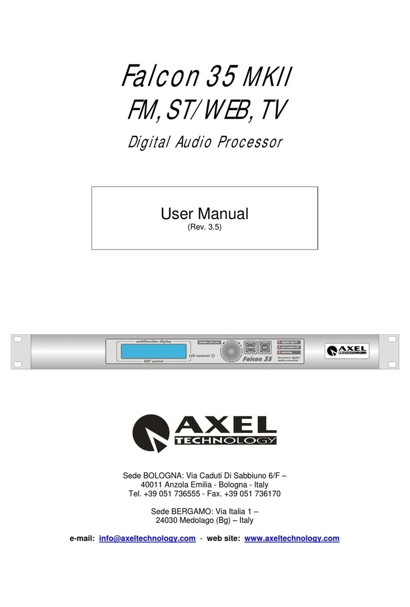
Axel Falcon 50 FM User manual

Operating manual
(Rel. 1.3)
PART ONE: INSTALLATION
Via Caduti Di Sabbiuno 6/F - 40011 Anzola Emilia - Bologna - Italy
Tel. +39 051 736555 – 051 736154 - Fax. +39 051 736170
e-mail: info@axeltechnology.com - web site: www.axeltechnology.com
Falcon 50 FM
6 Band DIGITAL audio PROCESSOR

Pag. 2

FOREWORD
ENG
Pag. 3
1 FOREWORD
F
rom all of us at Axel Technology, thank you for choosing the Falcon 50 FM digital
audio processor.
A great deal of effort went into the design and construction of this precision device.
With proper installation and calibration the processor will give you the most
accurate results for audio processing and modulation.
Take the time to go through the steps provided in this manual to ensure you get the
most out of your equipment.
Used properly, the Falcon 50 will give you many years of enjoyment.
Measurements of the Falcon 50 yield excellent results by any standards. However, the Falcon 50 audio quality can not
always be represented only by measures. We therefore invite You to a complete and enjoyable listening session...

ENG
Pag. 4
For your own safety and to avoid invalidation of the warranty all text marked with
these Warning Symbols should be read carefully.
Information in this manual is subject to change without notice and does not represent a commitment on the
part of the vendor.
Axel Technology shall not be liable for any loss or damage whatsoever arising from the use of information or
any error contained in this manual, or through any mis-operation or fault in hardware contained in the
product.
It is recommended that all maintenance and service on the product should be carried out by Axel Technology
or its authorised agents. Axel Technology cannot accept any liability whatsoever for any loss or damage
caused by service, maintenance or repair by unauthorised personnel.

TABLE OF CONTENTS
ENG
Pag. 5
2 TABLE OF CONTENTS
1
FOREWORD.........................................................................................................................................3
2
TABLE OF CONTENTS........................................................................................................................5
3
INTRODUCTION...................................................................................................................................6
3.1
APPROACHING
AN
FM
AUDIO
PROCESSOR..........................................................................................8
4
INSTALLATION CONSIDERATIONS ...................................................................................................9
5
BLOCK DIAGRAM ............................................................................................................................. 10
6
SAFETY WARNINGS......................................................................................................................... 11
7
FOREWORD....................................................................................................................................... 12
8
SAFETY WARNINGS......................................................................................................................... 13
9
CONSIGNES DE SÉCURITÉ IMPORTANTES.................................................................................... 15
10
ISTRUZIONI IMPORTANTI PER LA SICUREZZA........................................................................... 17
11
WICHTIGE SICHERHEITSHINWEISE............................................................................................. 19
12
INSTRUCCIONES IMPORTANTES DE SEGURIDAD..................................................................... 21
13
UNPACKING AND INSPECTION.................................................................................................... 23
14
FIRST INSTALLATION RECOMMENDATIONS.............................................................................. 24
14.1
POWER
SUPPLY
CABLE .........................................................................................................................24
14.2
AC
MAINS
VOLTAGE
SETTING
(230
V
/
115
V).....................................................................................24
14.3
FUSE
REPLACEMENT.............................................................................................................................25
14.4
PROTECTION
AGAINST
LIGHTNING ....................................................................................................25
14.5
VENTILATION .........................................................................................................................................26
15
AUDIO AND MPX GENERAL SETTINGS ....................................................................................... 27
15.1
AUDIO
INPUT
IMPEDANCE....................................................................................................................27
15.2
MPX
OUTPUT
SETTINGS........................................................................................................................28
16
GENERAL DESCRIPTION.............................................................................................................. 30
16.1
REAR
PANEL
VIEW.................................................................................................................................30
16.2
FRONT
PANEL
SOCKETS
AND
SIGNALLINGS .....................................................................................32
17
AUDIO I/O WIRING......................................................................................................................... 33
17.1
ANALOG
AUDIO
INPUT..........................................................................................................................33
17.2
ANALOG
AUDIO
OUTPUT ......................................................................................................................33
17.3
AUDIO
CABLING.....................................................................................................................................34
17.4
DIGITAL
AUDIO
INPUT...........................................................................................................................34
10.2.1
Converting between AES/EBU and S/PDIF interfaces..........................................................................34
17.5
DIGITAL
AUDIO
OUTPUT.......................................................................................................................34
17.6
DIGITAL
AUDIO
SYNCHRONIZATION
INTERFACE............................................................................35
18
COMMUNICATION PORTS, AUDIO JACK AND GPI/O WIRING.................................................... 36
18.1
SERIAL
PORT ...........................................................................................................................................36
18.2
USB
PORTS...............................................................................................................................................37
10.2.1
INSTALLING USB DRIVERS ..............................................................................................................37
18.3
ETHERNET
PORT*...................................................................................................................................39
18.4
GP
INPUT
INTERFACE ............................................................................................................................40
18.5
GP
OUTPUT
INTERFACE.........................................................................................................................42
18.6
FRONT
HEADPHONE
SOCKET...............................................................................................................43
18.7
MPX
AND
AUX
CONNECTIONS.............................................................................................................44
19
INSTALLING THE REMOTE CONTROL SOFTWARE.................................................................... 45

INTRODUCTION
ENG
Pag. 6
3 INTRODUCTION
Congratulations on your purchase of the Falcon 50 FM. The Axel Technology design team is confident you
will enjoy the outstanding performance of the DAP for many years. In case you are interested in technical
details, what follows is a brief outline of some of the key technologies in your new processor.
A brief overview
Relying on Axel Technology’s extensive know-how in audio processing techniques, the Falcon 50 FM has
been designed and built using a new approach that incorporates the most up-to-date components and
technologies. Its efficient design allows the Falcon 50 to produce top-level results in a cost-effective way.
The largest control set allows you to paint a truly unique and competitive on-air sound: from detailed and flat
to heavy and loud. Its exceptional audio quality is maintained even at extreme settings.
The largest connection capabilities
Whether your audio system contains analog, digital or both formats, the Falcon 50 FM can be configured to
fit in perfectly. A sophisticated module allows flexible switching between inputs, e.g. for emergency purpose.
Fail-safe operation is assured by an internal bypass on all the audio and MPX I/O circuits.
Two Composite Baseband Outputs are provided, each with independent level control. The MPX clipping
stage is user-enable and adjustable. MPX power can be limited accordingly to ITU R-BS 412 Specification.
Two serial RS232 ports, an USB port and a TCP/IP Ethernet connection (the latter available as an option)
permit remote control and monitoring from almost any location through the use of a standard PC and the
dedicated control software which comes with the unit.
User-friendly controls
Falcon 50 FM set-up is quick and easy, thanks to a wizard based on less/more controls. User-configurable
remote control functions (including preset programming) are available through optocoupled inputs. For more
convenience, a complete day-part automation is also completely self-contained.
Control from anywhere
The Falcon 50 can be remotely controlled, either from a locally attached computer, or from anywhere in the
world.
There are many ways to do this.
- Using Falcon 50’s IP connection or modem connection you can control processor from any where in the
world using the provided remote Control Software.
- Falcon 50’s serial and USB interfaces allow you to connect any PC running the provided remote Control
Software.
- Falcon50’s programmable TTL inputs give you six “contact closure” inputs that can be used to control
certain functions, like ‘switch audio input’ or ‘change audio curve’.
State-of-art circuitation and plenty of headroom
Falcon 50’s analog and digital audio input and output circuits are state-of-the-art for high quality, low noise
and low distortion audio. The processor’s levels on analog input assure plenty of headroom for all
applications without the need for audio limiters. Professional quality AES/EBU digital audio input and output,
with internal high-quality rate converters are standard.

INTRODUCTION
ENG
Pag. 7
Built-in automatic audio changeover
The Falcon 50 features two inputs: analog and digital.
The selection between inputs may be achieved manually or the programme source may be forced to either
input Analog or input Digital by activating one of six GP Input, accordingly to Source Selection menu.
The Falcon 50 also incoporates an audio detector stage, which can be used to automatically select between
two identical stereo programme paths (Analog or Digital), in the event the main program runs under-
threshold (set at – 35 dB), extinguishes or the difference on levels between Left and Right channels exceeds
20 dB.
Once the Falcon 50 has switched from Main to Stand-by input, the Main input may be kept monitored till the
Main audio input resumes. Also when Main audio appears, a settable time may be awaited before inverse
switching (from B to A) is performed.
OPTIONAL FEATURES DESCRIPTION
TCP –IP The TCP IP interface allows users to view/take control of Falcon 50 from any
Windows machine networked with the processor.
NOTE: the present manual describes the processor in its complete configuration. Depending on the
chosen configuration and on the chosen options, Yr actual equipment might not provide some of the
here-below described features or controls.

INTRODUCTION
ENG
Pag. 8
3.1 APPROACHING AN FM AUDIO PROCESSOR
An audio processor is a nonlinear process, that is, even if the ouput signal might be slightly more attractive in
respect to the input signal, it has surely more distortion respect to the input.
For this reason, always try to use the cleanest possible audio material to get the cleanest ouput audio and
remember that the correct adjustment of a multiband processor is a quite complicated task, so, don’t be
frustrated if after thirty minutes you still cannot get your sound.
Remember also that “extreme loudness” settings are well suited only for certain kinds of music (pop, disco,
rap…) while are awful for other kinds of music; so always adapt the processor to the format of your radio.
General settings often sound well with most music formats even if they have not the same loudness.
The output sound is always a trade-off between loudness distortion and cleaness and you must choose the
trade-off between them according your taste.
Another last tip is that you might avoid the use of high stereo expander levels expecially with low bitrate
MP3s; MPEG compression puts a lot of “trash” into the stereo image so, often, enhancing the stereo image
you could enhance just “MPEG noise” (a sort of “tingling” you may hear at medium-high frequencies).
Last recommendation is to use a good quality audio board with a “flat” output, that is no further bass or treble
equalization must be added. This is the only way you may expect to have a good peak control and a
satisfactory audio quality.

INSTALLATION CONSIDERATIONS
ENG
Pag. 9
4 INSTALLATION CONSIDERATIONS
Installing the Falcon 50 requires a bit more than mounting it in the rack, connecting some cables, and then
putting it on the air.
Among the factors you should consider are:
1. Monitor Location. You should have a good location in which the system, once on the air, can be
monitored. We suggest a good tuner, with good reception, feeding a set of studio monitor speakers
to be sufficient. While car radio and other “typical listener situation” settings are important, they
should not be the main reference points.
2. Good, Clean Source Material. If you are using poor source material, or poor performing playback
equipment, you will not get maximum sonic benefit from your equipment. Anomalies that you
perceive to be processing problems, may be source problems that the processing is exaggerating!
Make sure that you start out with a good first step - good source material!
3. Mic Processing. This may appear trivial, but the perceived sound of “live” voices over the air can
change dramatically with different processing systems. Whatever the effect your on-air microphones
will probably change when you change your processing. If you utilize mic processing, you may have
to adjust it to suit the operation of the new processing system. Most announcers develop a “comfort
zone” with respect to the sound of their voice over the air. When that “comfort zone” is changed or
modified, the common response is that something is wrong. Mic processing can be a very important
part of your overall station sound.
4. Operating Levels. This is another simple area where trouble can develop. Make sure the input and
output levels of the processor are at the operating at the proper level within your system. If you are
comparing the Falcon 50 with other processors, be sure they are operating at the same levels. Your
modulation monitor is an important tool in any processing comparison.
Equipment internal Clock is powered by a capacitor instead of a traditional battery. The capacitor keeps the
clock operating and protects the system memory to prevent the loss of stored programs during power failure
around one week long (depending on the environmental conditions). Capacity charge needs at least 30’ of
normal operation. Clock tolerance might amount to about 1 sec per day.
A correct installation and an optimum level setting are crucial for a good operating and the exploitation of all
the equipment capabilities. Please pay attention to all notes contained in the user manual.

BLOCK DIAGRAM
ENG
Pag. 10
5 BLOCK DIAGRAM
OPTIONAL
32,44.1,48,96
KHz
47.5Ks/sec
D
I
G
I
T
A
L
A
N
A
L
O
G
Digital
Input
Analog
Input
AD Clipping
Point
Input
mode
switch
Primary
Input
Selector
Input
mode
switch
MPX
Power
Limiter
Hi-Pass
30Hz
Hi-Pass
30Hz
2-Band
AGC
Monitor
6-Band
6-Band
Opto Interface
6-Band
FM-Proc
FM-Proc
FM-Proc
FM-Proc
FM-Proc
DAB/IBOC
FM-Proc
Generator
EQ
Generator
Generator
Monitor
Multiband
Input
Input
Input
Input
Input
5-Band
C
O
M
P
R
E
S
S
O
R
L
I
M
I
T
E
R
E
X
P
A
N
D
E
R
Stereo
Enhancer
Super
Bass
External
Signals User
Command
ModulationFreq.
Mode
Selection Command
Logic
Phase
Rotator
Phase
Rotator
Look
Ahead
Limiter
&
Expander
A
U
X
2
A
U
X
3
A
U
X
1
A
N
A
L
O
G
H
E
A
D
P
H
O
N
E
S
D
I
G
I
T
A
L
D
A
B
I
B
O
C
M
P
X
2
M
P
X
1
O
U
T
O
U
T
O
U
T
O
U
T
O
U
T
O
U
T
I
N
I
N
I
N
I
N
I
N
Input EQ
Block diagram
1°
2°
3°
4°
5°
6°
1°
2°
3°
4°

SAFETY WARNINGS
ENG
Pag. 11
6 SAFETY WARNINGS
SAFETY WARNINGS
CONSIGNES DE SÉCURITÉ IMPORTANTES
ISTRUZIONI IMPORTANTI PER LA SICUREZZA
WICHTIGE SICHERHEITSHINWEISE
INSTRUCCIONES IMPORTANTES DE SEGURIDAD
(Rel. 1.0)

FOREWORD
ENG
Pag. 12
7 FOREWORD
For your own safety and to avoid invalidation of the warranty all text marked with these Warning
Symbols should be read carefully.
Information in this manual is subject to change without notice and does not represent a commitment on the
part of the vendor.
The manufacturer shall not be liable for any loss or damage whatsoever arising from the use of information
or any error contained in this manual, or through any mis-operation or fault in hardware contained in the
product.
It is recommended that all maintenance and service on the product should be carried out by the
manufacturer or its authorised agents. The manufacturer cannot accept any liability whatsoever for any loss
or damage caused by service, maintenance or repair by unauthorised personnel.

SAFETY WARNINGS
ENG
Pag. 13
8 SAFETY WARNINGS
The installation and servicing instructions in this manual are for use by qualified personnel only.
- Read All Instructions. All safety and operating instructions must be read before operating the product.
They also must be retained for future reference, as it contains a number of useful hints for determining
the best combination of equipment settings for Yr particular application.
- Heed All Warnings. All warnings on the product and those listed in the operating instructions must be
adhered to.
- Heat. This product must be situated away from any heat sources such as radiators or other products
(including power amplifiers or transmitters) that produce heat.
- Power Sources. This product must be operated from the type of power source indicated on the marking
label and in the installation instructions. If you are not sure of the type of power supplied to your facility,
consult your local power company. Make sure the AC main voltage corresponds to that indicated in the
technical specifications. If a different voltage (ex. 110/115 VAC) is available, open the equipment closure
and set the voltage switch on the main supply circuit, located behind the AC socket
- Power Cord Protection. Power supply cords must be routed so that they are not likely to be walked on
nor pinched by items placed upon or against them. Pay particular attention to the cords at AC wall plugs
and convenience receptacles, and at the point where the cord plugs into the product
- Clean only with dry cloth
-
Use only with a cart, stand, tripod, bracket, or table specified by the manufacturer, or sold with
the apparatus. When a cart is used, use caution when moving the cart/apparatus combination
to avoid injury from tip-over.
- Lightning. For added protection for this product during a lightning storm, or when it is left unattended and
unused for long periods of time, unplug it from the AC wall outlet and the audio connections. This will
prevent damage to the product due to lightning and power line surges
- Installation. Configuration and installation should only be carried out by a competent installation engineer
- Cabling. Using high quality wires, well protected. Make sure the cable integrity.
- Equipment design. This manual images could differ a bit from the equipment actual design
This symbol alerts you to the presence of dangerous voltage inside the closure –
voltage which may be sufficient to constitute a risk of shock. Do not perform any
servicing other than that contained in the operating instructions. Refer all servicing
to qualified personnel
The exclamation point within an equilateral triangle is intended to alert the user to the
presence of important operating and maintenance (servicing) instructions in the
literature accompanying the appliance.

SAFETY WARNINGS
ENG
Pag. 14
Do not change the voltage setting or replace the mains fuse without first turning the
unit off and unplugging the mains cord.
This apparatus must be EARTHED !
To avoid risk of fire use the correct value fuse, as indicated on the label stuck on the
right side of the unit.
Make sure the AC main voltage corresponds to that indicated in the technical
specifications.
This apparatus uses a single pole mains switch and does therefore not separate the
unit completely from the mains power. To completely separate from mains power (f.i.
in the event of danger) unplug mains power cord. As the MAINS plug as the
disconnect device, the disconnect device shall remain readily operable.

CONSIGNES DE SÉCURITÉ IMPORTANTES
ENG
Pag. 15
9 CONSIGNES DE SÉCURITÉ IMPORTANTES
- Lire ces consignes
- Conserver ces consignes
- Observer tous les avertissements
- Suivre toutes les consignes
- Ne pas utiliser cet appareil à proximité de l’eau
- Nettoyer uniquement avec un chiffon sec
- Ne pas obstruer les ouvertures de ventilation. Installer en respectant les consignes du fabricant
- Ne pas installer à proximité d'une source de chaleur telle qu'un radiateur, une bouche de chaleur, un
poêle ou d'autres appareils (dont les amplificateurs) produisant de la chaleur.
- Ne pas annuler la sécurité de la fiche de terre, la troisième branche est destinée à la sécurité. Si la
fiche fournie ne s'adapte pas à la prise électrique, demander à un électricien de remplacer la prise hors
normes.
- Protéger le cordon d'alimentation afin que personne ne marche dessus et que rien ne le pince, en
particulier aux fiches, aux prises de courant et au point de sortie de l’appareil
- Utiliser uniquement les accessoires spécifiés par le fabricant
-
Utiliser uniquement avec un chariot, un support ou une table spécifié par le fabricant ou vendu
avec l’appareil. Si un chariot est utilisé, déplacer l’ensemble chariot–appareil avec précaution
afin de ne pas le renverser, ce qui pourrait entraîner des blessures
- Débrancher l’appareil pendant les orages ou quand il ne sera pas utilisé pendant longtemps.
- Confier toute réparation à du personnel qualifié. Des réparations sont nécessaires si l’appareil est
endommagé d’une façon quelconque, par exemple: cordon ou prise d’alimentation endommagé, liquide
renversé ou objet tombé à l’intérieur de l’appareil, exposition de l’appareil à la pluie ou à l’humidité,
appareil qui ne marche pas normalement ou que l’on a fait tomber.
- NE PAS exposer cet appareil aux égouttures et aux éclaboussements. Ne pas poser des objets
contenant de l'eau, comme des vases, sur l'appareil
Ce symbole indique la présence d'une tension dangereuse dans l'appareil constituant
un risque de choc électrique.
Ce symbole indique que la documentation fournie avec l'appareil contient des
instructions d'utilisation et d'entretien importantes.

CONSIGNES DE SÉCURITÉ IMPORTANTES
ENG
Pag. 16
Avant de modifier le commutateur de changement de tension ou replacer le fusible il
faut débrancher l’appareil de la prise électrique
Pendant son usage, l’appareil doit etre branchee à la prise de terre
Utiliser le fusible principal AC avec le valeur qui est indiquée sur l'étiquette collée sur
le coffret.
Assurez-vous que la tension principale AC correspond à celle indiquée dans les
spécifications techniques.
L’interrupteur d’alimentation interrompt un pôle du réseau d’alimentation excepté le
conducteur de terre de protection.
En cas de danger, debrancher le cordon d'alimentation. Parce que la prise du réseau
de alimentation est utilisée comme dispositif de déconnexion, ce dispositif doit
demeuré aisément accessible.

ISTRUZIONI IMPORTANTI PER LA SICUREZZA
ENG
Pag. 17
10 ISTRUZIONI IMPORTANTI PER LA SICUREZZA
- Leggere le presenti istruzioni
- Conservare queste istruzioni
- Osservare tutte le avvertenze
- Seguire scrupolosamente tutte le istruzioni
- Non usare questo apparecchio in prossimità di acqua
- Pulire l'apparecchio solo con un panno asciutto.
- Non ostruire alcuna apertura per il raffreddamento. Installare l’apparecchio seguendo le istruzioni
- Non installare l'apparecchio accanto a fonti di calore quali radiatori, aperture per l'afflusso di aria
calda, forni o altri apparecchi (amplificatori inclusi) che generino calore
- Non rimuovere il terminale di connessione a terra sul cordone di alimentazione: esso ha lo scopo di
tutelare l’incolumità dell’utilizzatore. Se la spina in dotazione non si adatta alla presa di corrente, rivolgersi
ad un elettricista per far eseguire le modifiche necessarie.
- Evitare di calpestare il cavo di alimentazione o di comprimerlo, specialmente in corrispondenza della
spina e del punto di inserzione sull’apparato.
- Utilizzare solo dispositivi di collegamento e gli accessori specificati dal produttore.
-
Utilizzare l’apparecchio solo con un carrello, un sostegno, una staffa o un tavolo di tipo
specificato dal produttore o venduto insieme all’apparecchio. Se si utilizza un carrello, fare
attenzione negli spostamenti per evitare infortuni causati da ribaltamenti del carrello stesso
- Scollegare l’apparecchio dalla presa di corrente durante i temporali o quando inutilizzato a lungo
- Per qualsiasi intervento, rivolgersi a personale di assistenza qualificato. È’ necessario intervenire
sull’apparecchio ogniqualvolta si verificano danneggiamenti di qualsiasi natura. Ad esempio, la spina o il
cavo di alimentazione sono danneggiati, è entrato liquido nell’apparecchio o sono caduti oggetti su di
esso, l’apparecchio è stato esposto alla pioggia o all’umidità, non funziona normalmente o è caduto.
- Non esporre a sgocciolamenti o spruzzi. Non appoggiare sull'apparecchio oggetti pieni di liquidi, ad
esempio vasi da fiori.
Questo simbolo indica la presenza di alta tensione all'interno dell'apparecchio, che
comporta rischi di scossa elettrica.
Questo simbolo indica la presenza di istruzioni importanti per l'uso e la manutenzione
nella documentazione in dotazione all'apparecchio.

ISTRUZIONI IMPORTANTI PER LA SICUREZZA
ENG
Pag. 18
Non sostituire il fusibile o cambiare la tensione di alimentazione senza aver prima
scollegato il cordone di alimentazione.
L’apparato deve essere connesso a terra durante il suo utilizzo.
Sostituire il fusibile generale con uno di identico valore, come indicato sulla etichetta
applicata sul mobile dell’apparato.
Assicurarsi che la tensione di rete corrisponda a quella per la quale è configurato
l’apparecchio.
Questo apparato utilizza un interruttore di alimentazione di tipo unipolare e
l’isolamento dalla rete elettrica non è pertanto completo.
Per ottenere un isolamento totale (ad esempio in caso di pericolo), scollegare il
cordone di alimentazione. Inoltre, poichè la spina di alimentazione è utilizzata come
dispositivo di sezionamento, essa deve restare facilmente raggiungibile.

WICHTIGE SICHERHEITSHINWEISE
ENG
Pag. 19
11 WICHTIGE SICHERHEITSHINWEISE
- Diese Hinweise LESEN
- Diese Hinweise AUFHEBEN
- Alle Warnhinweise BEACHTEN
- Alle Anweisungen BEFOLGEN
- Dieses Gerät NICHT in der Nähe von Wasser verwenden
- NUR mit einem sauberen Tuch REINIGEN
- KEINE Lüftungsöffnungen verdecken. Gemäß den Anweisungen des Herstellers einbauen
- Nicht in der Nähe von Wärmequellen, wie Heizkörpern, Raumheizungen, Herden oder anderen
Geräten (einschließlich Verstärkern) installieren, die Wärme erzeugen
- Die Schutzfunktion des Schukosteckers NICHT umgehen. Bei Steckern für die USA gibt es
polarisierte Stecker, bei denen ein Leiter breiter als der andere ist; US-Stecker mit Erdung verfügen über
einen dritten Schutzleiter. Bei diesen Steckerausführungen dient der breitere Leiter bzw. der Schutzleiter
Ihrer Sicherheit. Wenn der mitgelieferte Stecker nicht in die Steckdose passt, einen Elektriker mit dem
Austauschen der veralteten Steckdose beauftragen
- VERHINDERN, dass das Netzkabel gequetscht oder darauf getreten wird, insbesondere im Bereich
der Stecker, Netzsteckdosen und an der Austrittsstelle vom Gerät
- NUR das vom Hersteller angegebene Zubehör und entsprechende Zusatzgeräte verwenden.
-
NUR in Verbindung mit einem vom Hersteller angegebenen oder mit dem Gerät verkauften
Transportwagen, Stand, Stativ, Träger oder Tisch verwenden. Wenn ein Transportwagen
verwendet wird, beim Verschieben der Transportwagen-Geräte- Einheit vorsichtig
vorgehen, um Verletzungen durch Umkippen
- Das Netzkabel dieses Geräts während Gewittern oder bei längeren Stillstandszeiten aus der Steckdose
ABZIEHEN.
- Alle Reparatur- und Wartungsarbeiten von qualifiziertem Kundendienstpersonal DURCHFÜHREN
LASSEN. Kundendienst ist erforderlich, wenn das Gerät auf irgendwelche Weise beschädigt wurde, z.B.
wenn das Netzkabel oder der Netzstecker beschädigt wurden, wenn Flüssigkeiten in das Gerät
verschüttet wurden oder Fremdkörper hineinfielen, wenn das Gerät Regen oder Feuchtigkeit ausgesetzt
war, nicht normal funktioniert oder fallen gelassen wurde.
- Dieses Gerät vor Tropf- und Spritzwasser SCHÜTZEN. KEINE mit Wasser gefüllten Gegenstände wie
zum Beispiel Vasen auf das Gerät STELLEN.
Dieses Symbol zeigt an, dass gefährliche Spannungswerte, die ein Stromschlagrisiko
darstellen, innerhalb dieses Geräts auftreten.
Dieses Symbol zeigt an, dass das diesem Gerät beiliegende Handbuch wichtige
Betriebs- und Wartungsanweisungen enthält.

WICHTIGE SICHERHEITSHINWEISE
ENG
Pag. 20
Vor Änderung der Netzspannung oder Sicherungswechsel Netzkabel trennen.
Das Gerät muss für den Betrieb geerdet werden.
Hauptsicherung nur mit einer gleichwertigen austauschen
(s. entsprechende Etikette).
Vor Einschalten Netzspannungseinstellung am Gerät überprüfen bzw. anpassen.
Inpoliger Netzschalter. In Notfälle oder für Wartungsarbeiten Netzkabel trennen. Der
Netzstecker fungiert auch als Trennelement muss deshalb zugänglich bleiben
Table of contents
Other Axel Computer Hardware manuals
Popular Computer Hardware manuals by other brands

Renesas
Renesas PROM Programming Adapters PCA7441 user manual

Behringer
Behringer Sonic Exciter SX3040 quick start guide

AXIOMTEK
AXIOMTEK CAPA311 user manual

NXP Semiconductors
NXP Semiconductors i.MX 8QuadXPlus quick start guide

AJA
AJA IO LA Installation and operation guide

EK-Quantum
EK-Quantum Momentum2 ROG Strix X570-i Gaming D-RGB manual