AXIOMTEK GOT610-837 User manual

GOT610-837
10.4”XGA TFT
For Heavy-Duty Vehicle
Touch Panel Computer
User’s Manual

ii
Disclaimers
This manual has been carefully checked and believed to contain accurate information.
Axiomtek Co., Ltd. assumes no responsibility for any infringements of patents or rights of any
third party, and any liability arising from such use.
Axiomtek does not warrant or assume any legal liability or responsibility for the accuracy,
completeness or usefulness of any information in this document. Axiomtek does not make any
commitment to update the information in this manual.
Axiomtek reserves the right to change or revise this document and/or product at any time
without notice.
No part of this document may be reproduced, stored in a retrieval system, or transmitted, in
any form or by any means, electronic, mechanical, photocopying, recording, or otherwise,
without the prior written permission of Axiomtek Co., Ltd.
CAUTION
Wrong type of batteries may cause explosion. It is recommended that users only replace with
the same or equivalent type of batteries as suggested by the manufacturer once properly
disposing of any used ones.
Copyright 2019 Axiomtek Co., Ltd.
All Rights Reserved
June 2019, Version A1
Printed in Taiwan

iii
Safety Precautions
Before getting started, read the following important precautions.
1. Be sure to ground yourself to prevent static charge when installing the internal
components. Use a grounding wrist strap and place all electronic components in any
static-shielded devices. Most electronic components are sensitive to static electrical
charge.
2. Disconnect the power cords from the GOT600 Series before making any installation. Be
sure both the system and the external devices are turned OFF. Sudden surge of power
could ruin sensitive components. Make sure the GOT600 series is properly grounded.
3. Do not open the top cover of the system. If opening the cover for maintenance is a must,
only a trained technician is allowed to do so. Integrated circuits on computer boards are
sensitive to static electricity. To avoid damaging chips from electrostatic discharge,
observe the following precautions:
Before handling a board or integrated circuit, touch an unpainted portion of the
system unit chassis for a few seconds. This will help to discharge any static
electricity on a human body.
When handling boards and components, wear a grounding wrist strap, available
from most electronic component stores.
Trademark Acknowledgments
Axiomtek is a trademark of Axiomtek Co., Ltd.
Windows®is a trademark of Microsoft Corporation.
IBM, PC/AT, PS/2, VGA are trademarks of International Business Machines Corporation.
Intel®and Pentium®are trademarks of Intel Corporation.
AMI is trademark of American Megatrend Inc.
Other brand names and trademarks are the properties and registered brands of their
respective owners.

iv
Table of Contents
Disclaimers.....................................................................................................ii
Safety Precautions........................................................................................iii
Chapter 1 Introduction............................................. 1
1.1 General Description............................................................................1
1.2 Specifications......................................................................................2
1.2.1 Main CPU Board ......................................................................................... 2
1.2.2 I/O System................................................................................................... 2
1.2.3 System Specifications ................................................................................. 3
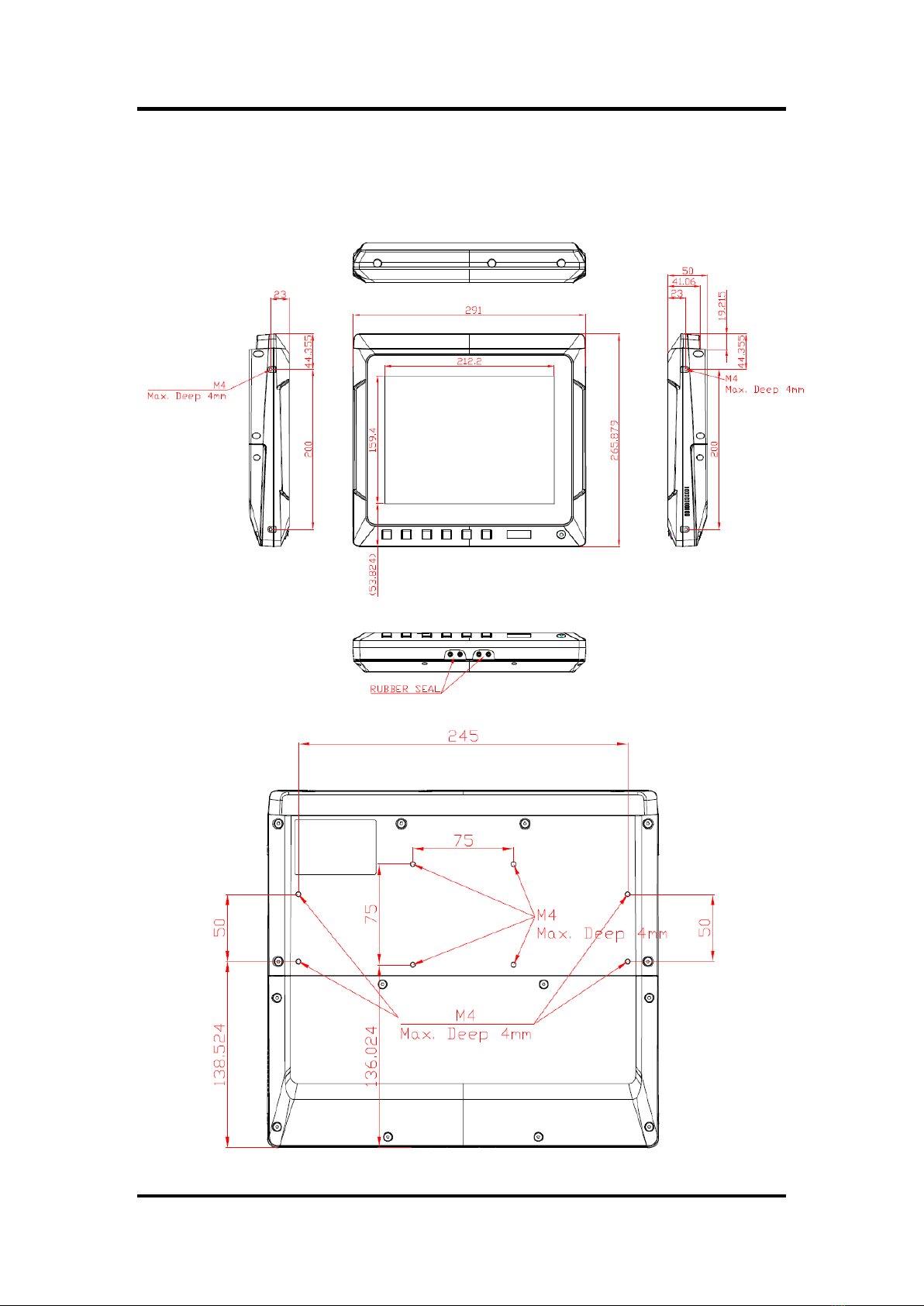
1.3 Dimensions..........................................................................................4
1.4 I/O Outlets............................................................................................5
1.5 Packing List.........................................................................................6
Chapter 2 Hardware and Installation ...................... 7
2.1 Open cover ..........................................................................................8
2.2 Vin 9-60VDC.........................................................................................9
2.3 CANBus................................................................................................9
2.4 COM 1 (Serial Port Connector) .......................................................10
2.5 USB 2.0...............................................................................................10
2.6 LAN.....................................................................................................11
2.7 DIO......................................................................................................12
2.7.1 Digital I/O Specification ............................................................................. 12
2.7.2 Digital I/O Software Programming............................................................. 13
2.7.3 Digital Input Wiring.................................................................................... 14
2.7.4 Digital Output Wiring................................................................................ 15
2.8 Mini card Installation.........................................................................16
2.8.1 WiFi/3G Module Installation ...................................................................... 16
2.8.2 mSATA Card Installation............................................................................ 17
2.9 System jumper settings....................................................................18
2.10 Hard keys Management....................................................................19
2.10.1 API Programming Library.......................................................................... 19
2.10.2 APP_Configuration Center........................................................................ 19
2.11 LED indicators...................................................................................20
2.12 Auto-dimming....................................................................................20
Chapter 3 AMI BIOS Setup Utility .......................... 21
3.1 Starting...............................................................................................21

v
3.2 Menu Bar............................................................................................22
3.3 Navigation Keys ................................................................................22
3.4 Main Menu..........................................................................................23
3.5 Advanced Menu.................................................................................24
3.6 Chipset Menu.....................................................................................31
3.7 Security Menu....................................................................................33
3.8 Boot Menu..........................................................................................34
3.9 Exit Menu...........................................................................................35
Chapter 4 Drivers and Installation ....................... 37
4.1 System ...............................................................................................37
4.2 Touch Screen.....................................................................................37
4.3 Configuration Center Software ........................................................40
4.3.1 Started Install Configuration .................................................................... 40
4.3.2 Configuration Center................................................................................. 42

vi
This page is intentionally left blank.

GOT610-837 User’s Manual
Introduction 1
Chapter 1
Introduction
This chapter contains general information and detailed specifications of the GOT610-837,
including the following sections:
General Description
Specifications
Dimensions
I/O Outlets
Package List
1.1 General Description
GOT610-837 is a fanless and compact-size touch panel computer, equipped with a 10.4” XGA
LCD display and low power consumption Intel○RAtom®E3845 1.91GHz processor. The
GOT610-837 supports Windows®7, Windows® 8.1, Windows® 10 and Linux Yocto OSs. In
addition, this panel computer provides two Mini card slots of full-size for extension. Its excellent
ID and friendly user interface make it a professional yet easy-to-use panel computer. The
GOT610-837 is ideal for vehicle-mounted terminal applications in heavy-duty vehicles,
especially suited for forklift and fleet management systems.
Sunlight readable design
Its sunlight readable technology with LED tech high brightness 500 nits color display allows the
screen legible even strong sunlight.
Wide operating temperature
The Intel® Atom® -based Vehicle panel PC, GOT610-837, applies unique extended
temperature technology with wide temperature range support as well as fanless operation. It
also has a compact design for heavy-duty transport environment.
Designed for vehicle markets
The Axiomtek GOT610-837 is particularly suitable for demanding HMI applications in the
vehicle-mounted sector, including arranging stocks and picking goods up and away.

GOT610-837 User’s Manual
2 Introduction
1.2 Specifications
1.2.1 Main CPU Board
CPU
Intel®AtomTM E3845 1.91GHz processor onboard (Bay Trail).
System memory
One DDR3L-1333 MHz(Bay Trail-I) 4GB
Maximum onboard memory up to 8 GB
BIOS
America Megatrends UEFI BIOS
1.2.2 I/O System
Standard I/O
1 x RS-232/422/485 with isolated 1.5KV (default RS-232)
4 x USB 2.0 (three in I/O line, one in top side)
1 x DIO with isolated 1.5KV D-Sub connector (6 input / 2 output)
1 x CAN bus with isolated / D-Sub connector
Ethernet
One Intel®i-210IT Gigabit Ethernet (PXE and LAN wake up)
Audio
1 x Audio: Line out, MIC in
Expansion
2 x Mini PCI-E card with full-size
Storage
16 GB flash onboard
1 x mSATA

GOT610-837 User’s Manual
Introduction 3
1.2.3 System Specifications
10.4”TFT LCD
10.4”XGA 500 nits, resolution 1024 x 768
5 wired resistive touch
IP65/ NEMA 4 protection, plastic front bezel
Net weight
2.05 Kgs (4.52 lb)
Dimension (main body size)
291 mm x 266 mm x 50 mm
Operation temperature
-30°C to +55°C
Relative humidity
10% to 95% @ 40°C, Non-Condensing
Power input
9~60VDC
Vibration
Refer to IEC60721-3-5 Class 5M3
10 to 500 Hz, 3.38G, random for 2.5”SSD
NOTE
1. All specifications and images are subject to change without notice.
2. The GOT610-837 has been designed particularly for operation in harsh environments;
please choose a wide-temperature SSD.
3. It is recommended to use a wide-temperature SSD if the operation temperature is
higher than 45
℃
.

GOT610-837 User’s Manual
4 Introduction
1.3 Dimensions
The following diagrams show the dimensions and outlines of the GOT610-837.

GOT610-837 User’s Manual
Introduction 5
1.4 I/O Outlets
Please refer to the following illustration for I/O locations of the GOT610-837.
Definitions of the front hot keys:
Definitions of the rear I/O functions:
No
Function
No
Function
1
DC-in
6
3 x USB 2.0 type A
2
AX/ATX mode switch
7
DIO (6-in/2-out)
3
CANBus
8
1 x RS-232/422/485
4
1 x Line-out
9
1 x LAN
5
1 x Mic-in
10
2 x Wireless antenna hole

GOT610-837 User’s Manual
6 Introduction
Definitions of the top side USB / SIM card slot / Antenna:
No
Function
11
3G/LTE/WIFI antenna hole
12
3G/LTE SIM slot
13
USB 2.0 A type
1.5 Packing List
A complete bundled package of the GOT610-837 should contain the following items:
GOT610-837 unit x 1
Driver CD x1
Phoenix connector x 2 (Power 4Pin * 1 / DIO 12Pin * 1)
Please contact an Axiomtek distributor immediately if you cannot find the package or any of the
above-mentioned items is missing.

GOT610-837 User’s Manual
Hardware and Installation 7
Chapter 2
Hardware and Installation
The GOT610-837 provides rich I/O ports and flexible expansions for you to meet different
demands. The chapter explains how to install the hardware parts, including:
Open cover: I/O cover, and back cover
Vin 9-60VDC
Serial ports
USB ports
Ethernet
DIO
Audio
CANBus
DC power
Mini card
System jumper setting
System panel header
Hard keys on front bezel
LED indicators
Auto-dimming

GOT610-837 User’s Manual
8 Hardware and Installation
2.1 Open cover
This section tells users how to open back covers. Please follow the steps below.
Open I/O Cover
Unscrew eight screws on the I/O cover. Please refer the photo below.
Open back cover
Unscrew six screws on the back cover. Please refer to the photo below.

GOT610-837 User’s Manual
Hardware and Installation 9
2.2 Vin 9-60VDC
The DC-in connector has four pins, as shown in the pin assignment table below.
Pin
Description
Definition
1
V+
For DC power in V+.
2
ACC
For ACC (Ignition)
3
V-
For DC power in V-
4
G
Chassis GND
2.3 CANBus
This system supports one CANBus with isolated 1.5KV. The pin assignments are listed in the
table below.
Pin
Definition
1
NA
2
CAN_LO
3
ISO3_GND
4
NA
5
NA
6
ISO3_GND
7
CAN_HO
8
NA
9
NA

GOT610-837 User’s Manual
10 Hardware and Installation
2.4 COM 1 (Serial Port Connector)
The COM1 connector is a standard DB-9 connector. The pin assignments of
RS-232/RS-422/RS-485 are listed on the following table. If you need COM port to support
RS-422 or RS-485, please select the matching COM port type from the BIOS items.
Pin
RS-232
RS-422
RS-485
1
DCD, Data carrier detect
TX-
Data-
2
RXD, Receive data
TX+
Data+
3
TXD, Transmit data
RX+
NC
4
DTR, Data terminal ready
RX-
NC
5
GND, ground
NC
NC
6
DSR, Data set ready
NC
NC
7
RTS, Request to send
NC
NC
8
CTS, Clear to send
NC
NC
9
RI, Ring indicator
NC
NC
2.5 USB 2.0
This system supports four USB ports which are located in the rear side and the top side. The
pin assignments are listed in the table below.
Pin
Signal USB Port 0
1
USB VCC
2
USB #0_D-
3
USB #0_D+
4
Ground (GND)

GOT610-837 User’s Manual
Hardware and Installation 11
2.6 LAN
The system is equipped with an RJ-45 connector for Gigabit LAN. To connect the board to a
10/100/1000 Base-T hub, just plug one end of the cable into LAN, and connect the other end
to a 10/100/1000 Base-T hub.
Pin
Description
1
MDI0+
2
MDI0-
3
MDI1+
4
MDI2+
5
MDI2-
6
MDI1-
7
MDI3+
8
MDI3-

GOT610-837 User’s Manual
12 Hardware and Installation
2.7 DIO
2.7.1 Digital I/O Specification
This system supports one DIO (6 input and 2 output) with isolated 1.5KV. The pin assignments
are listed in the table below.
Digital Input:
Input channels: 6, Dry/Wet type
Input voltage: 0 to 30VDC at 25Hz
Input level for dry contacts:
Logic level 0: close to ground
Logic level 1: open
Input level for wet contacts:
Logic level 1: +/-3VDC max.
Logic level 0: +/- 10VDC min. to +/-30VDC max. (source to digital input)
Digital output:
Output channels: 2, sink type
Output current: 200mA max. per channel
On-state voltage:12~ 24VDC nominal
Max. voltage on COM+: 30VDC
Pin
Definition
1
Common PWR+
2
DI4
3
DI5
4
DO0
5
DO1
6
Common PWR-
7
EXT_POWER
8
DI0
9
DI1
10
DI2
11
DI3
12
Isolation GND

GOT610-837 User’s Manual
Hardware and Installation 13
2.7.2 Digital I/O Software Programming
I2C to GPIO PCA9554PW GPIO Group0[3:0] is Output, Group0[7:4] is Input.
I2C address: 0b0100100x.
Registers:
Register 0: Input Group0 register.
Register 2: Output Group0 register.

GOT610-837 User’s Manual
14 Hardware and Installation
2.7.3 Digital Input Wiring
DRY contact
Logic level 0: close to ground Logic level 1: open
WET contact
Logic level 1: +/-3VDC max.
Logic level 0: +/- 10VDC min. to +/-30VDC max
Table of contents
Popular Automobile Accessories manuals by other brands

Cruz
Cruz Rafter Assembly instructions

Kolpin Outdoors
Kolpin Outdoors 35-1030 Assembly and installation manual

Aerpro
Aerpro Connects 2 FP8225 installation manual

Volvo
Volvo 32296522 user guide

dirna Bergstrom
dirna Bergstrom Bycool Scania Compact 1.4 Mounting instructions

Aqua-Hot
Aqua-Hot 600 series Use and care guide