Axis T8123-E Midspan 1-p User manual

Users Guide
ENGLISH DEUTSCH ITALIANO ESPAÑOL
FRAN
Ç
AIS
AXIS T8123-E Midspan 1-p
AXIS T8124-E Midspan 1-p

Legal Considerations
Video and audio surveillance can be prohibited by laws that
vary from country to country. Check the laws in your local
region before using this product for surveillance purposes.
Electromagnetic Compatibility (EMC)
This equipment has been designed and tested to fulfill
applicable standards for:
• Radio frequency emission when installed according to the
instructions and used in its intended environment.
• Immunity to electrical and electromagnetic phenomena
when installed according to the instructions and used in
its intended environment.
USA - This equipment has been tested using a shielded
network cable (STP) and found to comply with the limits for
a Class B digital device, pursuant to part 15 of the FCC
Rules. These limits are designed to provide reasonable
protection against harmful interference in a residential
installation. This equipment generates, uses and can radiate
radio frequency energy and, if not installed and used in
accordance with the instructions, may cause harmful
interference to radio communications. However, there is no
guarantee that interference will not occur in a particular
installation. If this equipment does cause harmful
interference to radio or television reception, which can be
determined by turning the equipment off and on, the user is
encouraged to try to correct the interference by one or more
of the following measures:
• Reorient or relocate the receiving antenna.
• Increase the separation between the equipment and
receiver.
• Connect the equipment into an outlet on a circuit
different from that to which the receiver is connected.
• Consult the dealer or an experienced radio/TV technician
for help.
Canada - This Class B digital apparatus complies with
Canadian ICES-003.
Europe - This digital equipment fulfills the
requirements for RF emission according to the Class B limit
of EN 55022.
Australia - This digital equipment fulfills the
requirements for RF emission according to the Class B limit
of AS/NZS CISPR 22.
Safety
This product complies to EN/IEC/UL 60950-1 and
EN/IEC/UL 60950-22, Safety of Information Technology
Equipment.
Japan - この装置は、クラスB 情報技術装置です。
この装置は、家庭環境で使用することを目 的として
いますが、この装置がラジオやテレビジョン受信機
に近接して使用されると、 受信障害を引き起こすこ
とがあります。 取扱説明書に従って正しい取り扱い
をして下さい。
Korea -
ࢇЕɼࢽࡈ%ࢷળࢶଢԻ۰
࣯Իɼࢽ߾۰یࡈଜЕʨࡶּࢶࡳԻଜֲֻҘ
ࠇ߾۰یࡈଟܹݡТЬ
Equipment Modifications
This equipment must be installed and used in strict
accordance with the instructions given in the user
documentation. This equipment contains no
user-serviceable components. Unauthorized equipment
changes or modifications will invalidate all applicable
regulatory certifications and approvals.
Liability
Every care has been taken in the preparation of this
document. Please inform your local Axis office of any
inaccuracies or omissions. Axis Communications AB cannot
be held responsible for any technical or typographical errors
and reserves the right to make changes to the product and
documentation without prior notice. Axis Communications
AB makes no warranty of any kind with regard to the
material contained within this document, including, but not
limited to, the implied warranties of merchantability and
fitness for a particular purpose. Axis Communications AB
shall not be liable nor responsible for incidental or
consequential damages in connection with the furnishing,
performance or use of this material. This product is only to
be used for its intended purpose.
RoHS
This product complies with both the European RoHS
directive, 2002/95/EC, and the Chinese RoHS
regulations, ACPEIP.
WEEE Directive
The European Union has enacted a Directive
2002/96/EC on Waste Electrical and Electronic
Equipment (WEEE Directive). This directive is
applicable in the European Union member states.
The WEEE marking on this product (see right) or
its documentation indicates that the product
must not be disposed of together with household waste. To
prevent possible harm to human health and/or the
environment, the product must be disposed of in an
approved and environmentally safe recycling process. For
further information on how to dispose of this product
correctly, contact the product supplier, or the local
authority responsible for waste disposal in your area.
Business users should contact the product supplier for
information on how to dispose of this product correctly. This
product should not be mixed with other commercial waste.
Support
Should you require technical assistance, please contact
your Axis reseller. If your questions cannot be answered
immediately, the reseller will forward your queries
through the appropriate channels to ensure rapid
response. If you are connected to the Internet, you can:
• Download user documentation
• Find answers to resolved problems in the FAQ database
• Search by product, category, or phrases
• Visit Axis Support at www.axis.com/techsup/
• Report problems to Axis support by logging in to your
private support area

ENGLISH
Safeguards
• Store the Axis product in a dry and ventilated environment.
• Avoid exposing the Axis product to vibration, shocks or heavy pressure. Do not install the product on
unstable brackets, unstable or vibrating surfaces or walls, since this could cause damage to the
product.
• Only use applicable tools when installing the Axis product; excessive force could cause damage to the
product.
• Do not use chemicals, caustic agents, or aerosol cleaners. Use a damp cloth for cleaning.
• Use only accessories that comply with technical specification of the product. These can be provided by
Axis or a third party.
• Installation and removal of the PoE Midspan must be carried out by qualified personnel only.
• Read the installation instructions before connecting the PoE Midspan to its power source.
• Follow basic electricity safety measures whenever connecting the PoE Midspan to its power source.
• A voltage mismatch can cause equipment damage and may pose a fire hazard. If the voltage indicated
on the label is different from the power outlet voltage, do not connect the PoE Midspan to this
power outlet.
• The equipment is intended only for installation in a Restricted Access Location.
• All wiring and connections shall be in accordance with NFPA 70 (NEC). Applicable to US only
• This product is fitted with a NEMA 5-15P plug for connection to the branch circuit. If other
attachment methods are required, please reference local codes and requirements for proper connection
to the branch circuit.
• This product is not intended to become a permanent part of the building structure.
• Power supply cord must not be attached to the building surface nor run through walls, ceilings, floors
and similar openings in the building structure.
• Measures must be taken to prevent physical damage to the power supply cord, including
proper routing.
• The PoE Midspan "DATA IN" and "DATA PWR OUT" ports are shielded RJ-45 data sockets. They cannot
be used as Plain Old Telephone Service (POTS) sockets. Only RJ-45 data connectors can be connected to
these sockets.
• Ensure cable length from Ethernet network source does not exceed 100 m (333 ft). The PoE is not a
repeater and does not amplify the Ethernet data signal.
• Use a splitter if desired, ensure that the splitter is connected close to the terminal and not on the Mid-
span.
• The PoE Midspan AC power plug shall be connected to a sealed box in order to meet EN60529 level
IP66 and NEMA 250 level 4x.
• The PoE Midspan AC power lines shall be connected to the socket-outlet, which shall be installed near
the equipment and easily accessible.
• Designed to meet GR-1089-CORE lightning protection demands.
• This Axis product shall be used in compliance with local laws and regulations.
• Do not attempt to repair the product by yourself, contact Axis or your Axis reseller for service matters
• Installation and removal of the T8123-E/T8124-E must be carried out by qualified personnel only.


AXIS T8123-E/T8124-E Users Guide Page 5
ENGLISH
AXIS T8123-E/T8124-E
Package Contents
Note: Ethernet cable and RJ-45 male connectors and mounting screws are not part of the delivery
Functions and Features
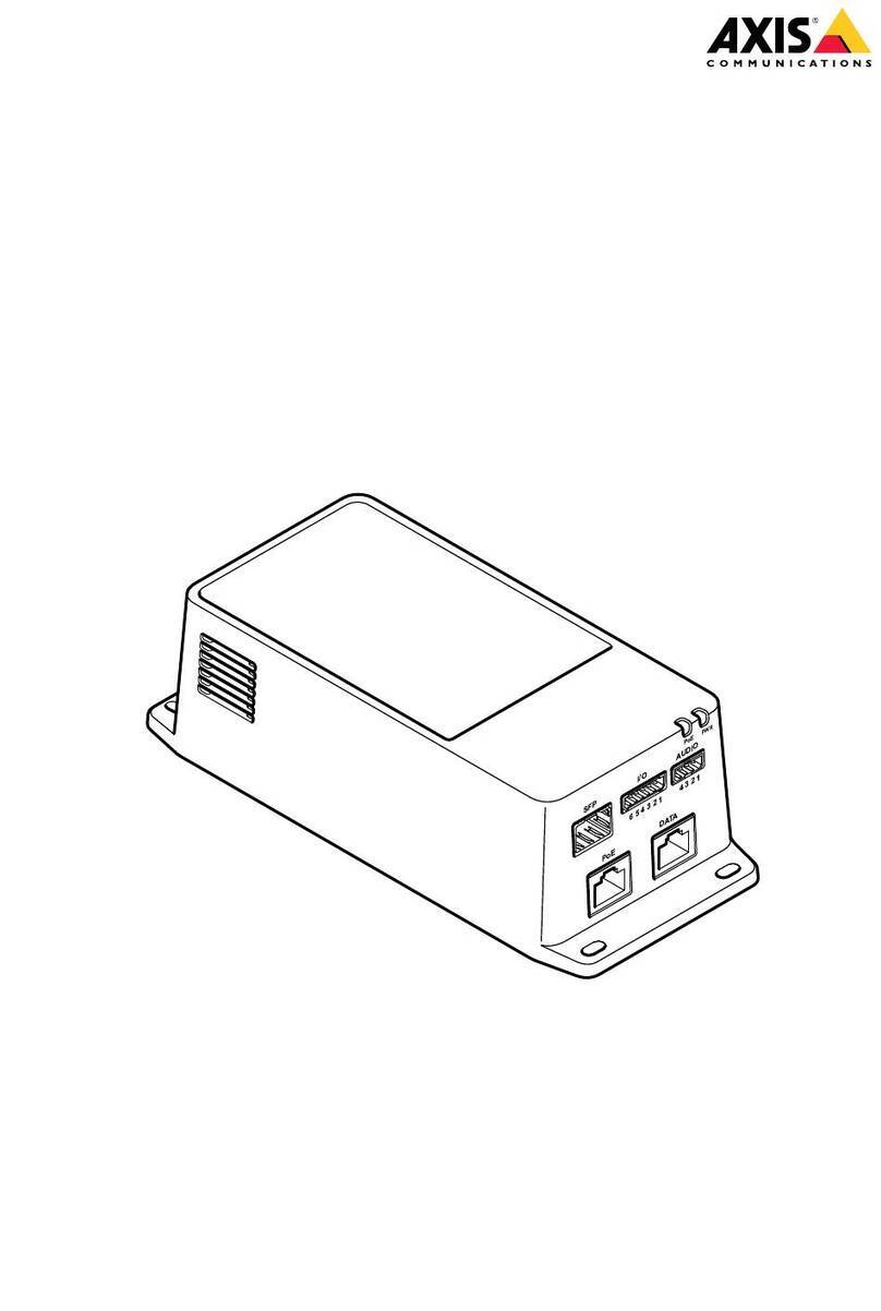
The AXIS T8123-E/T8124-E 1-Port 802.3at Gigabit PoE Outdoor Midspan injects power over data
carrying Ethernet cabling. It maintains IEEE802.3at and IEEE802.3af standards. These power levels
allow usage by a new range of Ethernet-based applications such as video phones, 802.11n Access
Points, WiMAX Transmitters, PTZ cameras and more. AXIS T8123-E/AXIS T8124-E DATA PWR OUT
port is designed to carry Gigabit Ethernet data and power over a standard CAT5e cable, delivered
through 4-pairs (Alt A: pins 1,2(-) / 3,6(+) and Alt B: pins 4,5(+) / 7,8(-)).
AXIS T8123-E/T8124-E
Midspan with pre-installed power cable
(power cable country specific)
International
USA
Mounting kit 2X RJ-45 male plug waterproof
connectors covers
Grounding wire
Printed material Users Guide (this document)
Warranty documents
AC power cable color code
USA Black, White and Green
International Blue, Brown and Yellow-Green

Page 6 AXIS T8123-E/T8124-E Users Guide
Mounting Instructions
The AXIS T8123-E/T8124-E may be wall or bench mounted using the rear side holes.
Note the following before mounting the AXIS T8123-E/T8124-E to a fixed location:
• Do not cover the midspan or block the airflow to the product with any foreign object. Keep
the midspan away from excessive heat and humidity, and free from vibration and dust.
• Ensure that the cable length from the Ethernet network source to your Axis video product
does not exceed 100 meters (333 ft). The midspan is not a repeater and does not amplify
the Ethernet data signal.
• There is no "on-off" switch; simply plug the AXIS T8123-E/T8124-E into an
AC power outlet.
To mount:
1. Fasten the AXIS T8123-E/T8124-E with three screws. See Fig 1 (screw holes are marked1,2,3)
2. Connect one end of the grounding wire to EARTH GROUND (see fig 1b) and the other end to an
appropriate ground location.
Note: When mounting the AXIS T8123-E/T8124-E make sure to use appropriate screws and plugs
for the surface (wood, concrete etc.). Do not unscrew the four pre-mounted screws
located in every corner of the product.
46.36
196
Fig 1 Fig 1b
1
EARTH GROUND
2 3

AXIS T8123-E/T8124-E Users Guide Page 7
ENGLISH
Installing the Unit
1. Thread male plug waterproof connector cover (A,B and C) on to the Ethernet cable. See Fig 3.
2. Attach the Ethernet cable to DATA IN. See Fig 2
3. Thread plug (A) over the RJ-45 male plug, connected to DATA IN. See Fig 3.
4. Thread housing (B) over the plug and screw (hand tight only). See Fig 3
5. Thread cover (C) over the connector and screw (hand tight only). See Fig 3
6. Repeat steps 2 to 6 for DATA PWR OUT
7. Connect the PoE Midspan to an AC power line (100-240 VAC)
Note: Do not use cross over cable between PoE Midspan output port and load device
DATA IN DATA PWR OUT
LINE AC
Fig 3
Fig 2
RJ-45 male plug
waterproof
connector
cover
RJ-45
male plug
ABC

Page 8 AXIS T8123-E/T8124-E Users Guide
Specifications
Environmental
* Applies to both AXIS T8123-E and AXIS T8124-E
Electrical
Interface
Mode Temperature Humidity
Operating
T8123-E
-40°C to 50°C for 30 Watts (-40°F to 131°F)
-40°C to 65°C for 15,4 Watts (-40°F to149°F) 10 to 95% (no condensation allowed)
Operating
T8124-E
-40°C to 50°C for 60 Watts (-40°F to 131°F)
-40°C to 65°C for 30 Watts (-40°F to 149°F)
Storage* -40°C to 85°C (-40°F to 185°F)
Input Voltage 100-240 VAC (50/60 Hz)
Input Current T8123-E 1 Ampere (max)
Input Current T8124-E 2 Ampere (max)
Available Output Power (max) T8123-E 30 Watt
Available Output Power (max) T8124-E 60 Watt
Nominal Output Voltage 55 VDC
Input (DATA IN):
Ethernet 10/100/1000Base-T
RJ-45 female socket
Output (DATA PWR OUT):
Ethernet 10/100/1000Base-T, plus 55VDC
RJ-45 female socket, with DC voltage on wire pairs
1-2 & 3-6, 4-5 & 7-8.
Power Cable (LINE AC) Pre-installed 3m power cable
AC power cable color code
USA Black, White and Green
International Blue, Brown and Yellow-Green

AXIS T8123-E/T8124-E Users Guide Page 9
ENGLISH
Troubleshooting
Warranty
For information about Axis product warranty and thereto related information, see
www.axis.com/warranty
Symptom Corrective Steps
Midspan does
not power up 1. Verify a reliable power cord is used.
2. Verify voltage at the power inlet is between 100-240Vac.
3. Remove and reapply power to the device and check the indicators during
power up sequence.
A port indicator
is not lit and the
device does not
operate
1. Verify the Midspan detects a device.
2. Verify that the device is designed for PoE operation
3. Verify you are using a standard Category 5/5e/6, straight-wired cable, with
four pairs.
4. If an external power splitter is in use, replace it with a known good splitter
5. Ensure input Ethernet cable is connected to the DATA IN port.
6. Verify that the device is connected to the DATA PWR OUT port.
7. Try to reconnect the same PD into a different Midspan. If it works, there is
probably a faulty port or RJ-45 connection.
8. Verify there is no short over any of the twisted pair cables or over the
RJ-45 connectors.
The end device
operates, but
there is no link
data link
1. Verify the port indicator on the front panel is continuously lit.
2. If an external power splitter is in use, replace it with a known-good splitter.
3. Verify that for this link, you are using standard UTP/FTP Category 5 straight
(non-crossover) cabling, with all four pairs.
4. Verify Ethernet cable length is less than 100 meters from Ethernet source to
load/remote terminal.
5. Try to reconnect the same PD into a different Midspan. If it works, there is
probably a faulty port or RJ-45 connection.


FRAN
Ç
AIS
Mesures de protection
• Conserver les produits Axis dans un environnement sec et ventilé.
• Ne pas exposer les produits Axis aux vibrations, chocs ou fortes pressions. Ne pas installer ce produit
sur des supports, surfaces ou murs instables ou soumis aux vibrations car cela pourrait endommager le
produit.
• Lors de l'installation du produit, n'utiliser que les outils appropriés; éviter d'appliquer une force
excessive car cela pourrait endommager le produit.
• Ne pas utiliser de produits chimiques, de substances caustiques ou de nettoyants pressurisés. Nettoyer
à l'aide d'un tissu humide.
• Utiliser uniquement les accessoires compatibles aux spécifications techniques du produit. Ceux-ci
peuvent être fournis par Axis ou un tiers.
• L'installation et le retrait de l'Injecteur PoE doit se faire uniquement par un technicien qualifié.
• Avant le branchement de l'Injecteur PoE à sa source d'alimentation, lire les instructions d'installation.
• Respecter toutes les mesures de sécurité électrique élémentaires lors du branchement de l'Injecteur
PoE à sa source d'alimentation.
• Une discordance de tension peut entraîner l'endommagement de l'équipement et un risque d'incendie.
Si la tension indiquée sur l'étiquette est différente de la tension de sortie, ne pas brancher l'Injecteur
PoE à cette sortie d'alimentation.
• L'équipement est destiné uniquement à l'installation dans un Emplacement à Accès Restreint.
• Tout le câblage et les branchements doivent se faire conformément à la norme NFPA 70 (NEC).
Applicable aux États-Unis uniquement.
• Ce produit est équipé d'une prise NEMA 5-15P pour le branchement au circuit de dérivation. Si d'autres
méthodes de raccordement sont requises, bien vouloir se reporter aux codes et exigences locales pour
un branchement approprié au circuit de dérivation.
• Ce produit n'est pas destiné à s'intégrer à la structure du bâtiment.
• Le cordon d'alimentation ne doit pas être raccordé à la surface du bâtiment ni acheminé à travers les
murs, les plafonds, les planchers et d'autres ouvertures similaires dans la structure du bâtiment.
• Des mesures doivent être prises afin d'éviter des dommages physiques au cordon d'alimentation, dont
l'acheminement approprié.
• Les ports "DATA IN" et DATA PWR OUT" de l'Injecteur PoE sont des prises de données RJ-45. Elles ne
doivent pas servir comme des prises de service téléphonique de base (POTS). Uniquement des
connecteurs de données RJ-45 doivent être branchés à ces prises.
• S'assurer que la longueur jusqu'à la source du réseau Ethernet n'excède pas 100 m (333 pi). Le PoE
n'est pas un répéteur et n'amplifie pas le signal des données Ethernet.
• Utiliser un séparateur si nécessaire, en s'assurant que celui-ci est connecté près du terminal et non sur
l'Injecteur.
• La prise d'alimentation CA de l'Injecteur PoE doit être branchée à un boîtier scellé afin de répondre aux
normes EN60529 niveau IP66 et NEMA 250 niveau 4x.
• Les lignes d'alimentation CA de l'Injecteur PoE doivent être branchées à la prise de sortie, qui doit être
installée près de l'équipement et facile d'accès.
• Conçu pour répondre à la norme GR-1089-CORE relative à la protection contre la foudre.
• Ce produit doit être utilisé conformément aux lois et dispositions locales en vigueur.
• Ne pas essayer de dépanner ce produit, contacter Axis ou votre revendeur Axis pour l'entretien.
• L'installation et le retrait du T8123-E/T8124-E doit se faire uniquement par un technicien qualifié.


Page AXIS T8123-E/T8124-E Guide d'utilisation 13
FRAN
Ç
AIS
AXIS T8123-E/T8124-E
Contenu de l’emballage
Remarque : Le câble Ethernet, les connecteurs mâles RJ-45 et les vis de montage ne font pas
partie de la livraison
Fonctions et caractéristiques
L'injecteur externe AXIS T8123-E/T8124-E 1-Port 802.3at Gigabit PoE injecte de l'énergie dans le
câble Ethernet de transfert de données. Il respecte les normes IEEE802.3at et IEEE802.3af. Ces
niveaux de puissance permettent une utilisation par une nouvelle gamme d'applications basées sur
Ethernet telles que les téléphones vidéos, les points d'accès 802.11n, les transmetteurs WiMAX, les
caméras PTZ, etc. Le port DATA PWR OUT de l'AXIS T8123-E/AXIS T8124-E est conçu pour
transmettre les données en Gigabit Ethernet et l'alimentation à travers un câble CAT5e standard,
délivré grâce à 4 paires (Alt A : pins 1,2(-) / 3,6(+) et Alt B : pins4,5(+) / 7,8(-)).
AXIS T8123-E/T8124-E
Injecteur avec cordon d'alimentation pré-
installé (cordon d'alimentation spécifique
par pays)
International
États-Unis
Kit de montage 2X Connecteur d'étanchéité RJ-45
Fil de mise à la terre
Documentation imprimée Manuel d'utilisation (ce document)
Documents relatifs à la garantie
Code couleur du cordon d'alimentation CA
États-Unis Noir, Blanc et Vert
International Bleu, Marron et Jaune-vert

Page 14 AXIS T8123-E/T8124-E Guide d'utilisation
Instructions de montage
AXIS T8123-E/T8124-E peut être monté sur un mur ou sur établi à l'aide des trous situés à l'arrière.
Prendre les précautions suivantes avant de monter AXIS T8123-E/T8124-E sur un emplacement fixe:
• Ne recouvrez pas l'injecteur ou ne bloquez pas son système d'aération par des corps
étrangers. Conservez l'injecteur à l'abri des excès de la chaleur et de l'humidité, des
vibrations et de la poussière.
• S'assurez que la longueur du câble à partir de la source d'Ethernet à votre produit vidéo
Axis ne dépasse pas 100 mètres (333 pi). L'injecteur n'est pas un répéteur et il n'amplifie
pas le signal des données Ethernet.
• Il ne possède pas de contacteur "marche-arrêt", branchez simplement AXIS T8123-E/
T8124-E dans une prise d’adaptateur secteur CA.
Pour le montage:
1. Fixer l'AXIS T8123-E/T8124-E avec les trois vis. Voir Fig 1 (Les trous de vis sont marqués 1,2,3)
2. Connectez une extrémité du fil de mise à la terre à EARTH GROUND (voir fig 1b) et l'autre
extrémité à un emplacement approprié au niveau du sol.
Remarque :
Lors du montage de l'AXIS T8123-E/T8124-E, assurez-vous d'utiliser les vis et les
connecteurs appropriés pour la surface de montage (bois, béton, etc.) Évitez de dévisser les
quatre vis pré-installées qui se trouvent à chaque coin du produit.

Page AXIS T8123-E/T8124-E Guide d'utilisation 15
FRAN
Ç
AIS
46.36
196
Fig 1 Fig 1b
1
EARTH GROUND
2 3

Page 16 AXIS T8123-E/T8124-E Guide d'utilisation
Installation de l’injecteur
1. Passez le connecteur d´étanchéité (A, B et C) au travers du câble Ethernet. Voir Fig 3.
2. Connectez le câble Ethernet à DATA IN. Voir Fig 2
3. Glissez le connecteur d´étanchéité (A) sur le connecteur mâle RJ-45, connecté à DATA IN. Voir
Fig 3
4. Glissez la bague de serrage (B) sur le connecteur d´étanchéité puis vissez (serrage à la main
uniquement). Voir Fig 3
5. Glissez la bague d´étanchéité (C) sur le connecteur d´étanchéité puis vissez (serrage à la main
uniquement). Voir Fig 3
6. Repétez les étapes 2 à 6 pour DATA PWR OUT
7. Connectez l'injecteur PoE à une source d'alimentation CA (100-240 VAC)
Remarque : Évitez d'utiliser un câble croisé entre le port de sortie de l'injecteur PoE et le
périphérique à alimenter.
DATA IN DATA PWR OUT
LINE AC
Fig 3
Fig 2
Connecteur
d´étanchéité
RJ-45
Connecteur mâle RJ-45
ABC

Page AXIS T8123-E/T8124-E Guide d'utilisation 17
FRAN
Ç
AIS
Caractéristiques techniques
Conditions d'utilisation
* S'applique à AXIS T8123-E et AXIS T8124-E
Électrique
Interface
Mode Température Humidité
En
fonctionnement
T8123-E
-40°C à 50° pour 30 Watts (-40°F à 131°)
-40°C à 65° pour 15,4 Watts (-40°F à 149°F) 10 à 95% (pas de condensation)
En
fonctionnement
T8124-E
-40°C à 50°C pour 60 Watts (-40°F à 131°F)
-40°C à 65° pour 30 Watts (-40°F à 149°)
Stockage* de -40° à 85° (de -40° à 185°)
Tension d’entrée 100-240 VAC (50/60 Hz
Courant d'entrée de T8123-E 1 Ampère (max)
Courant d'entrée de T8124-E 2 Ampère (max)
Puissance de sortie disponible (max)
T8123-E
30 Watts
Puissance de sortie disponible (max)
T8124-E
60 Watts
Tension de sortie nominale 55 VCC
Entrée (DATA IN):
Ethernet 10/100/1000Base-T
Fiche femelle RJ-45
Sortie (DATA PWR OUT):
Ethernet 10/100/1000Base-T, plus 55VDC
Fiche femelle RJ-45 avec tension CC sur les paires
de conducteurs 1-2 & 3-6, 4-5 & 7-8.
Cordon d'alimentation (LINE AC) Câble d'alimentation pré-installé 3m
Code couleur du cordon d'alimentation CA
États-Unis Noir, Blanc et Vert
International Bleu, Marron et Jaune-vert

Page 18 AXIS T8123-E/T8124-E Guide d'utilisation
Dépannage
Garantie
Pour plus d'informations sur la garantie des produits Axis et des informations générales relatives à
celle-ci de consulter le site www.axis.com/warranty
Problème Mesures correctives
L'injecteur ne se
met pas sous
tension.
1. Vérifiez la fiabilité du cordon d'alimentation utilisé.
2. Vérifiez si la tension de l'alimentation à l'entrée se trouve entre 100-
240Vac.
3. Déconnectez et reconnectez l'alimentation au produit et vérifiez les
indicateurs pendant la séquence de démarrage.
Le voyant port
est éteint et le
périphérique ne
fonctionne pas.
1. Vérifiez que l'injecteur détecte l'appareil.
2. Vérifiez que l'appareil est conçu pour un fonctionnement PoE
3. Assurez-vous d'utiliser un câble droit standard de catégorie 5/5e/6, avec
quatre paires.
4. Si un séparateur de puissance externe est utilisé, remplacer le par un
séparateur correct connu
5. S'assurez que le câble Ethernet d'entrée est connecté au port DATA IN.
6. Vérifiez que l'appareil est connecté au port DATA PWR OUT.
7. Essayez de reconnecter le même périphérique à alimenter sur un autre
injecteur. Si cela fonctionne, un port ou la connexion RJ-45 est
probablement défectueux.
8. Vérifiez s'il n'existe pas court-circuit sur un des câbles paires torsadées ou
sur les connecteurs RJ-45.
L'appareil en
bout fonctionne
mais, il n'existe
aucune liaison de
données
1. Vérifiez si l'indicateur du port sur le panneau avant est allumé de manière
continu.
2. Si un séparateur de puissance externe est utilisé, remplacer le par un
séparateur correct connu
3. Pour ce lien, assurez-vous d'utiliser un câble droit (pas croisé) standard
UTP/FTP de catégorie 5, avec quatre paires.
4. Vérifiez que la longueur du câble Ethernet est inférieure à 100 mètres à
partir de la source Ethernet au périphérique à alimenter.
5. Essayez de reconnecter le même périphérique à alimenter sur un autre
injecteur. Si cela fonctionne, un port ou la connexion RJ-45 est
probablement défectueux.

DEUTSCH
Sicherheitsvorkehrungen
• Lagern Sie das Axis-Produkt in einer trockenen und belüfteten Umgebung.
• Achten Sie darauf, dass das Axis-Produkt keinen Vibrationen, Stößen oder starkem Druck ausgesetzt
ist. Montieren Sie es nicht auf instabilen Halterungen oder auf instabilen und vibrierenden Oberflächen
oder Wänden. Dies könnte zu Beschädigungen des Produkts führen.
• Verwenden Sie zur Montage des Axis-Produkts geeignete Werkzeuge. Eine übermäßige
Kraftaufwendung kann das Produkt beschädigen.
• Verwenden Sie keine chemischen, ätzenden oder aerosolhaltigen Reinigungsmittel. Verwenden Sie zur
Reinigung ein feuchtes Tuch.
• Verwenden Sie nur Zubehör, das den technischen Spezifikationen des Produkts entspricht. Dieses ist
von Axis oder Drittanbietern erhältlich.
• Die Installation und Entfernung des PoE Midspan darf nur von qualifiziertem Personal ausgeführt
werden.
• Lesen Sie die Installationsanweisungen, bevor Sie den PoE Midspan an die Stromversorgung
anschließen.
• Befolgen Sie grundlegende Sicherheitsmaßnahmen für die Arbeit mit Elektrizität, wenn Sie den PoE
Midspan an die Stromversorgung anschließen.
• Eine falsche Spannung kann das Produkt beschädigen und eine Brandgefahr darstellen. Wenn sich die
auf dem Etikett angegebene Spannung von der Spannung der Steckdose unterscheidet, schließen Sie
den PoE Midspan nicht an diese Steckdose an.
• Das Produkt ist nur für die Installation an einem Ort mit beschränktem Zugang vorgesehen.
• Alle Verkabelungen und Anschlüsse müssen dem Standard NFPA 70 (NEC) entsprechen (nur in den
USA).
• Dieses Produkt ist mit einem NEMA 5-15P-Stecker zum Anschluss an eine Abzweigschaltung
ausgestattet. Wenn eine andere Anschlussmethode erforderlich ist, halten Sie sich an lokale Codes und
Anforderungen für den ordnungsgemäßen Anschluss an eine Abzweigschaltung.
• Dieses Produkt ist nicht dafür vorgesehen, ein permanentes Teil der Gebäudestruktur zu sein.
• Das Stromkabel darf nicht an der Gebäudeoberfläche befestigt noch durch Wände, Decken, Böden oder
ähnliche Öffnungen in der Gebäudestruktur geführt werden.
• Es müssen Maßnahmen ergriffen werden, um physische Schäden an der Stromversorgung zu
verhindern, einschließlich einer ordnungsgemäßen Verlegung.
• Bei den Anschlüssen DATA IN und DATA PWR OUT des PoE Midspan handelt es sich um isolierte RJ-45-
Datenbuchsen. Sie können als „Plain Old Telephone Service“ (POTS)-Buchsen verwendet werden. Es
können nur RJ-45-Datenstecker an diese Buchsen angeschlossen werden.
• Stellen Sie sicher, dass die Kabellänge von der Ethernet-Netzwerkquelle nicht 100 m (333 ft)
überschreitet. Der PoE ist kein Repeater und verstärkt damit nicht das Datensignal der Ethernet-
Verbindung.
• Verwenden Sie, falls gewünscht, einen Splitter; vergewissern Sie sich, dass der Splitter in der Nähe des
Endgeräts und nicht am Midspan sitzt.
• Der Wechselstromstecker des PoE Midspan muss an einen isolierten Anschlusskasten angeschlossen
werden, um die Norm EN60529 Stufe IP66 und den Standard NEMA 250 Stufe 4x zu erfüllen.
• Die Wechselstromleitungen des PoE Midspan müssen an eine Steckdose angeschlossen werden, die sich
in der Nähe des Geräts befindet und leicht zugänglich ist.
• Gemäß den Blitzschutzanforderungen des Standards GR-1089-CORE entwickelt.
DEUTSCH

• Verwenden Sie dieses Axis-Produkt unter Beachtung der geltenden rechtlichen Bestimmungen.
• Versuchen Sie nicht, das Produkt selbst zu reparieren. Wenden Sie sich bei Service-Angelegenheiten an
Axis oder an Ihren Axis-Händler.
• Die Installation und Entfernung des T8123-E/T8124-E darf nur von qualifiziertem Personal ausgeführt
werden.
Other manuals for T8123-E Midspan 1-p
1
This manual suits for next models
1
Table of contents
Languages:
Other Axis Cables And Connectors manuals
Popular Cables And Connectors manuals by other brands

Sennheiser
Sennheiser ASA 3000 instruction manual
Sony
Sony PEGA-HS10 Operating Instructions (primary... operating instructions

Philips
Philips SWV3133W Specifications
Cablexpert
Cablexpert DSP-2PH4-001 user manual
Sulzer
Sulzer AquaPlug Series Starting and operating instructions
Waters
Waters XSelect XP Care and use manual
