Axis A8105-E User manual

AXIS A8105-E installation
Relay powered by PoE (12V)
Relay Door DoorRELAY
NamePort TypeI/O Usage Normal state is... Current Status
Open circuitOpen circuit
Open circuit
Closed circuit
To check relay state, go to:
Setup > System Options > Ports & Devices > I/O ports
Depending on your lock type, congure the following values
for RELAY, and click Save.
Open circuit for a fail-secure lock
Closed circuit for a fail-safe lock
1.
2.
Configure relay state in AXIS A8105-E built-in
web pages
12Vl01 l02 CO
NO/
NC

Relay powered by separate power supply
AXIS A8105-E installation
Relay Door DoorRELAY
NamePort TypeI/O Usage Normal state is... Current Status
Open circuitOpen circuit
Open circuit
Closed circuit
To check relay state, go to:
Setup > System Options > Ports & Devices > I/O ports
Depending on your lock type, congure the following values
for RELAY, and click Save.
Open circuit for a fail-secure lock
Closed circuit for a fail-safe lock
1.
2.
Configure relay state in AXIS A8105-E built-in
web pages
12Vl01 l02 CO
NO/
NC
Power
supply

AXIS A8105-E installation
Potential-free relay
Relay Door DoorRELAY
NamePort TypeI/O Usage Normal state is... Current Status
Open circuitOpen circuit
Open circuit
Closed circuit
To check relay state, go to:
Setup > System Options > Ports & Devices > I/O ports
Depending on your lock type, congure the following values
for RELAY, and click Save.
Open circuit for a fail-secure lock
Closed circuit for a fail-safe lock
1.
2.
Configure relay state in AXIS A8105-E built-in
web pages
12Vl01 l02 CO
NO/
NC
Potential-free
contact

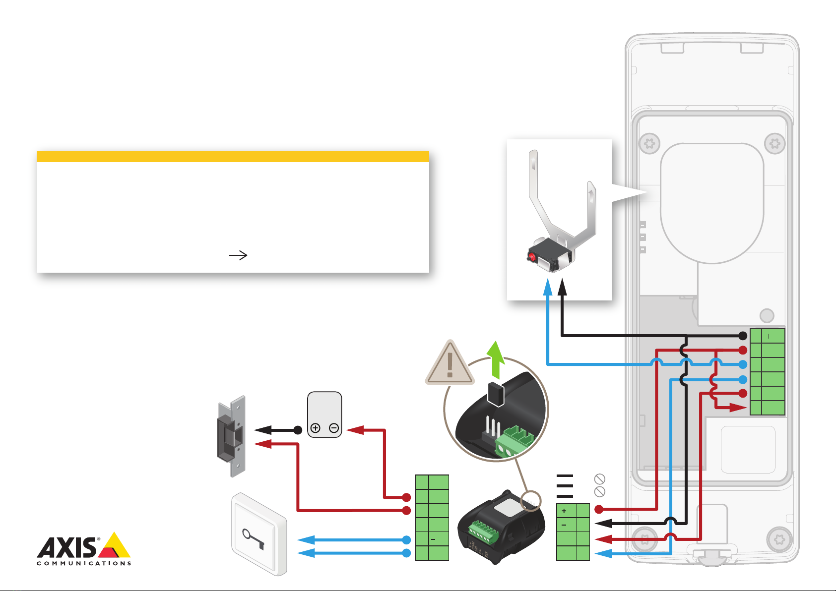
12V Fail-secure lock powered by PoE from door station
Recommended setup using AXIS TA8501 Physical Tampering Switch
AXIS A8105-E installation
These instructions apply when you use the recommended setup
for AXIS TA8501 Physical Tampering Switch with AXIS A9801
Security Relay.
See conguration on next page
Page 1/2
12Vl01 l02 CO
NO/
NC
I/O
REL
V+
COM
NO
NC
REX
12V
24V

1. To check relay and tampering state, go to:
Setup > System Options > Ports & Devices > I/O ports
2. Make sure the following values are congured for IO1.
Input TamperSwitch TamperingIO1
NamePort TypeI/O Usage Normal state is... Current Status
Open circuitOpen circuit
Relay Door DoorRELAY
NamePort TypeI/O Usage Normal state is... Current Status
Open circuitOpen circuit
Open circuit
Closed circuit
3. Depending on your lock type, congure the following values for RELAY,
and click Save.
Open circuit for a fail-secure lock
Closed circuit for a fail-safe lock
4. Go to: Setup > Events > Action Rules
5. Modify “TAMPERING: Tilt detected” to the following values and click OK.
Configure relay and tampering state in AXIS A8105-E
built-in web pages
Start condition only
Trigger: Input Signal
Digital Input Port
TamperSwitch (Port2)
Active: Yes No
Recommended setup using
AXIS TA8501 Physical Tampering Switch
Page 2/2

AXIS A8105-E installation
12V Fail-secure lock powered by PoE from door station
Optional setup using AXIS TA8501 Physical Tampering Switch
These instructions apply when you use the optional setup for
AXIS TA8501 Physical Tampering Switch with AXIS A9801 Security
Relay.
NOTE: With this setup you can't notify the user if the tampering
switch triggers, but IO1 is available for other use/congurations.
See conguration on next page
Page 1/2
12Vl01 l02 CO
NO/
NC
I/O
REL
V+
COM
NO
NC
REX
12V
24V

Optional setup using
AXIS TA8501 Physical Tampering Switch
Page 2/2
Configure relay and tampering state in AXIS A8105-E
built-in web pages
1. To check relay state, go to:
Setup > System Options > Ports & Devices > I/O ports
2. Depending on your lock type, congure the following values for RELAY,
and click Save.
Open circuit for a fail-secure lock
Closed circuit for a fail-safe lock
3. Go to: Setup > Events > Action rules
4. Clear the checkbox for the "TAMPERING: Tilt detected" action rule.
Relay Door DoorRELAY
NamePort TypeI/O Usage Normal state is... Current Status
Open circuitOpen circuit
Open circuit
Closed circuit
TAMPERING: Tilt detected Detectors - Tilt Detection - Output Port -
AXIS A8105-E installation
12V Fail-secure lock powered by external power supply
Recommended setup using AXIS TA8501 Physical Tampering Switch
These instructions apply when you use the recommended setup
for AXIS TA8501 Physical Tampering Switch with AXIS A9801
Security Relay.
See conguration on next page
Page 1/2
12Vl01 l02 CO
NO/
NC
I/O
REL
12V
24V
V+
COM
NO
NC
REX
Power
supply
Max 30V,
Max 1.2A

1. To check relay and tampering state, go to:
Setup > System Options > Ports & Devices > I/O ports
2. Make sure the following values are congured for IO1.
Input TamperSwitch TamperingIO1
NamePort TypeI/O Usage Normal state is... Current Status
Open circuitOpen circuit
Relay Door DoorRELAY
NamePort TypeI/O Usage Normal state is... Current Status
Open circuitOpen circuit
Open circuit
Closed circuit
3. Depending on your lock type, congure the following values for RELAY,
and click Save.
Open circuit for a fail-secure lock
Closed circuit for a fail-safe lock
4. Go to: Setup > Events > Action Rules
5. Modify “TAMPERING: Tilt detected” to the following values and click OK.
Configure relay and tampering state in AXIS A8105-E
built-in web pages
Start condition only
Trigger: Input Signal
Digital Input Port
TamperSwitch (Port2)
Active: Yes No
Recommended setup using
AXIS TA8501 Physical Tampering Switch
Page 2/2

AXIS A8105-E installation
12V Fail-secure lock powered by external power supply
Optional setup using AXIS TA8501 Physical Tampering Switch
These instructions apply when you use the optional setup for
AXIS TA8501 Physical Tampering Switch with AXIS A9801 Security
Relay.
NOTE: With this setup you can't notify the user if the tampering
switch triggers, but IO1 is available for other use/congurations.
See conguration on next page
Page 1/2
12Vl01 l02 CO
NO/
NC
I/O
REL
12V
24V
V+
COM
NO
NC
REX
Power
supply
Max 30V,
Max 1.2A
Other manuals for A8105-E
2
Other Axis Relay manuals


