Axpert KING 3KVA User manual

SERVICE MANUAL
3KVA/5KVA-230V
1
V201703A
3KVA/5KVA-230V
Service manual

SERVICE MANUAL
3KVA/5KVA-230V
2
V201703A
Table of contents
1. General information.............................................................................................................................................. 3
1.1 Getting start................................................................................................................................................. 3
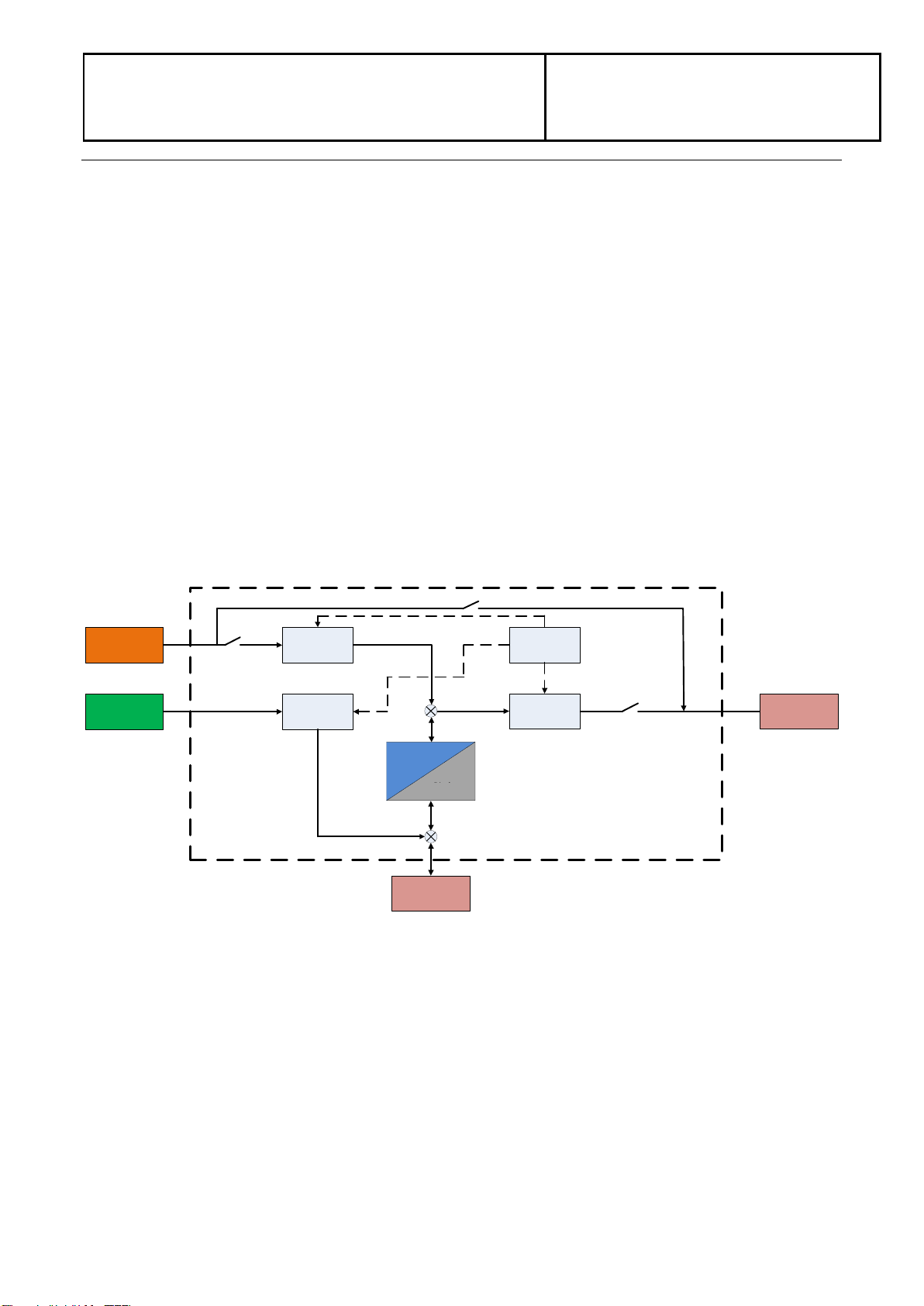
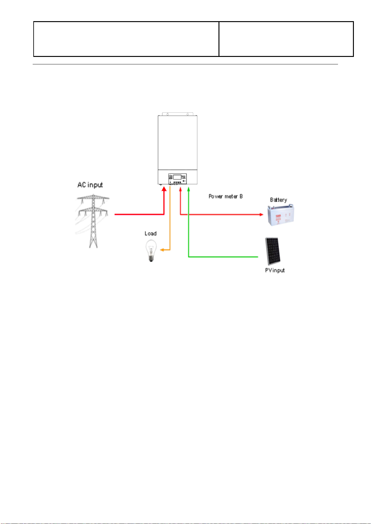
1.2 Basic topology introduction....................................................................................................................... 3
1.3 Inverter family.............................................................................................................................................. 4
1.4 Overview the inverter................................................................................................................................. 4
1.5 PCB overview.............................................................................................................................................. 5
2. Troubleshooting.................................................................................................................................................... 6
2.1 How to do..................................................................................................................................................... 6
2.2 Check the fault information....................................................................................................................... 6
2.3 Fault condition............................................................................................................................................. 7
2.4 Test step....................................................................................................................................................... 8
3. Checking and measuring guide.......................................................................................................................... 9
3.1 Check the battery side components........................................................................................................ 9
3.2 Check the bus side components............................................................................................................ 16
3.3 Check the buck circuit.............................................................................................................................. 18
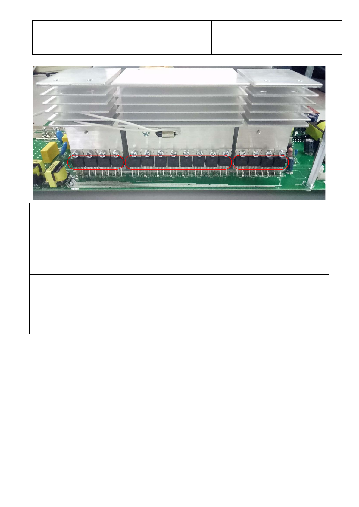
3.4 Check the INV full bridge ........................................................................................................................ 20
3.5 Check the MPPT board........................................................................................................................... 22
4. Disassembling guide.......................................................................................................................................... 23
4.1 Remove the REMOTE BOX ................................................................................................................... 23
4.2 Open the case........................................................................................................................................... 23
4.3 Remove all boards.................................................................................................. 錯誤! 尚未定義書籤。
5. Cables connection.............................................................................................................................................. 27

SERVICE MANUAL
3KVA/5KVA-230V
3
V201703A
1. General information
1.1 Getting start
This manual is used as a checking and repairing guide for 3KVA/5KVA-230V model. Before read this
manual, it’s better to have some electrical or electronic background knowledge. With this guide, you can
fix the inverter by yourself firstly.
There are five main parts of this guide:
General information: This part is the basic information of the inverter; you can start to know the inverter
from this chapter.
Troubleshooting: This part will tell you how to do when you face a problem.
Checking and measuring guide: This part will teach you how to check or repair the inverter by
measuring the critical components.
Assembling guide: This part teaches you how to take the board outside and fix the new one.
Cables connection: This part is a reference for cable connection.
1.2 Basic topology introduction
The topology of the inverter shows as below:
Solar Charger
Battery
Utility
Solar Load
Discharger
Charger
INV
PFC Control
Discharger
Compare with UPS or normal inverter, INVERTER combines a solar charger inside. Solar charger can be
a supplement for battery when there is not grid or for saving energy purpose. And with the solar charger,
the inverter can have more working modes than UPS. For detail information please refer to our user
manual.

SERVICE MANUAL
3KVA/5KVA-230V
4
V201703A
1.3 Inverter family
This service manual includes different models of the inverter, the table as below contains some important
parameters with different models.
These models names are only neutral names; please match the real model name of your inverter to the model
name in the table by comparing the typical characteristics.
Model name
Power rating
Solar charger
type
Solar charger
number
Off-grid/Hybrid
3KVA
3KVA/3KW
MPPT
1
Off-grid
5KVA
5KVA/5KW
MPPT
1
Off-grid
Note: Main board of 3KVA model is 16-501021-XXG, main board of 5KVA model is 16-501016-XXG.
1.4 Overview the inverter
COMM board
16-501026-XXG
IND board
16-501058-XXG
Main board
16-501021-XXG
CNTL board
16-501015-XXG
MPPT board
16-500689-XXG
CAP board
16-000259-XXG

SERVICE MANUAL
3KVA/5KVA-230V
5
V201703A
1.5 PCB overview
Main board:
Battery
connection
BAT+
BAT-
PFC
Inductance
location
Power
supply
BUS soft start
power supply
Inverter
Inductance Control board terminer FAN terminer
TX1
ISO
BUCK
Inductance
PFC
Inductance
terminer
Grid
terminer
Output
terminer
Connect
MPPT
battery
cables
Control board:
To PAR communication board
(31-550170-00G)
To communication board
(71-501026-00G)
To MPPT board
(31-550295-00G)

SERVICE MANUAL
3KVA/5KVA-230V
6
V201703A
MPPT board:
Solar connection
Battery connction
2. Trouble shooting
2.1 How to do
When the inverter was faulty, normally there are two main symptoms:
No display at all;
Fault code or warning code on the LCD;
When the fault occurred, please help to record the fault information and follow “How to check” of part 2.3
to check the inverter, then feedback the checking result to the service center. It will be very helpful for
solving the problem as soon as possible.
2.2 Check the fault information
Please follow the steps as below to find the issues!
Make sure that you can finish all the steps and feedback us the results. Or we may not be able to
give you the right solution.
Step 1: Test the battery working mode.
Before turning on the inverter, only connect the battery with the inverter which means no solar input and
grid input. Turn on the switch, the LCD will light up and wait for the battery connecting to load.
If the connection is failed, please record the fault code.
Step 2: Test the grid charging mode.
Before turning on the inverter, only connect the utility and battery with the inverter. Without press any
buttons, the LCD will light up.And wait for the utility connecting to battery.
If the connection is failed, please record the fault code.
Step 3: Test the solar charging mode.
Before turning on the inverter, only connect the solar and battery with the inverter. Without press any
buttons, the LCD will light up.And wait for the solar connecting to battery.
If the connection is failed, please record the fault code.

SERVICE MANUAL
3KVA/5KVA-230V
7
V201703A
2.3 Fault condition
Note:
When open the top cover, please have a look first, are there any obviously damaged parts?
When take the main board out, please have a look around, are there any obviously damaged
parts?
2.2.1. Not working at all/ No display
Description
The inverter couldn’t startup completely.
Possible reason
1. SPS module damaged.
How to check
1. Firstly, please measure the resistor between BAT+ and BAT-. If it is not shorted,
only connect the inverter with battery, and press “ON” button, could the inverter
startup? If not, please check the fan.
2. If the LCD couldn’t light up and fan doesn’t work, please disconnect all the wires
and open the top cover, and then take the main board outside by following part 4.
How to solve
Replace the main board.
2.2.2. 09 fault
Description
Bus soft start fails.
Possible reason
DC-DC module was damaged.
How to check
Check the main board by following “3.1~3.4”;
How to solve
Repair the main board or replace it directly.
2.2.3. 56 fault
Description
Battery couldn’t be detected.
Possible reason
Wire connection or fuse was burnt.
How to check
1. Check the wire connection, the priority of the battery cable;
2. Check the main board by following “3.1”.
How to solve
Repair the main board or replace it directly.

SERVICE MANUAL
3KVA/5KVA-230V
8
V201703A
2.4 Test step
After replacing all defected components, testing steps can be used to confirm the repair result and the
reliability of the Inverter.
Set up the testing system as below:

SERVICE MANUAL
3KVA/5KVA-230V
9
V201703A
3. Checking and measuring guide
3.1 Check the battery side components
Fuse and capacitors
F3
Parts
Attribute
Reference values
Failure status
F3
Resistor
0 ohm
Open
C9/C13/C8/C12
If the capacitors explode as below, they need to be replaced.
Power devices
DC/DC MOSFET: Q13/Q18/Q23 & Q11/Q17/Q20 & Q21/Q22/Q12 & Q26/Q25/Q14

SERVICE MANUAL
3KVA/5KVA-230V
10
V201703A
Q19 Q13 Q18 Q23 Q24 Q11 Q17 Q20 Q38 Q21 Q22 Q12 Q40 Q26 Q25 Q14
Parts
Attribute
Reference values
Failure status
All:
Resistor1
GS: 11.7K
GD: 250K
DS: 0.55M
Short or explosion
Diode
SD: 0.42V
DS: OL
Note1: When you use the multimeter to measure the resistor of the transistor, because of the capacitor in
the circuit, it will cause the changing of the values when you measure the DS and GD. So we recommend
you measure the diode forward voltage of SD, and the resistor of GS. These two values can reflect the
situation of the transistor more correctly.
Note: If one or more of them were damaged, please replace all of them.

SERVICE MANUAL
3KVA/5KVA-230V
11
V201703A
3.1.1. Drivers (This part is only used for repair checking)
Note: Drivers usually need to be checked when users want to repair the boards. Because when power
devices were damaged, the high voltage will rush to driver circuit through the gates of power devices.
The reference of the resistors list as below:
R41/R59/R70/R76/R80/R78/R75/R42/R52/R62/R81/R64/R93/R92/R87/R53
TVS1/ TVS2/ TVS3/ TVS4/ TVS6/ TVS7/ TVS8/ TVS10/ TVS11/ TVS12/ TVS14/ TVS15/ TVS16
TVS8 TVS7 TVS6 TVS5
TVS16
TVS15
TVS14
TVS13
TVS12
TVS11
TVS10
TVS9
TVS4 TVS3 TVS2 TVS1
Use multimeter to measure each resistor, find the burnt resistors and replace them; don’t need to replace
them all.
model
Parts
Attribute
Reference values
Failure status
3KVA
All: 33ohm
Resistor
33 ohm
Open or other values
TVS1-16
Diode
+ To - : 0.42V
Short or explosion
5KVA
All: 22ohm
Resistor
22 ohm
Open or other values
TVS1-16
Diode
+ To - : 0.42V
Short or explosion
If the resistors need to be replaced, please also check the driver transistors and control IC.

SERVICE MANUAL
3KVA/5KVA-230V
12
V201703A
Q46
Q47
Q49Q48
The Q46and Q48 are 11-300012-00G (TR 2A50V NPN TO-92)
The Q47and Q49 are 11-300005-00G (TR 2A50V PNP TO-92NL)
Q15
Q41
Q16
Q43
The Q41 and Q43 are 11-300012-00G (TR 2A 50V NPN TO-92)
The Q15 and Q16 are 11-300005-00G (TR 2A 50V PNP TO-92NL)
Parts
Attribute
Reference values
Failure status
Q46/Q48/Q41/Q43
Resistor
BE: 434.2k
BC: 429.3k
CE: 19.52k
Short or explosion

SERVICE MANUAL
3KVA/5KVA-230V
13
V201703A
Diode
BE: 0.656V
BC: 0.655V
CE: 1.3V
Q47/Q49/Q15/Q16
Resistor
BE: 433.5k
BC: 432.1k
CE: 8.1k
Short or explosion
Diode
BE: 0.656V
BC: 1.741V
CE: 0.2V
Q55 Q54 Q56 Q57
B E C
The Q54and Q56 are 11-400011-00G (TR 2A50V NPN SOT-89)
The Q55and Q57 are 11-400010-00G (TR 3A50V PNP SOT-89)
Q53 Q52 Q51 Q50
B E C
The Q51and Q52 are 11-400011-00G (TR 2A50V NPN SOT-89)
The Q50and Q53 are 11-400010-00G (TR 3A50V PNP SOT-89)

SERVICE MANUAL
3KVA/5KVA-230V
14
V201703A
Parts
Attribute
Reference values
Failure status
Q54/Q56/Q51/Q52
Resistor
BE: 12k
BC: 263.5K
CE: OL
Short or explosion
Diode
BE: 0.632V
BC: 0.631V
CE: OL
Q55/Q57/Q50/Q53
Resistor
BE: 12k
BC: OL
CE: 277.3k
Short or explosion
Diode
BE: 0.632V
BC: OL
CE: 1.107V
Q60 Q61
D
S G
The Q60 and Q61 are 11-420007-00G (MOSFET 5.8A30V SOT-23)
Parts
Attribute
Reference values
Failure status
Q60/Q61
Resistor
GS: 4.185k
GD: 12.08k
DS: 90k
Short or explosion
Diode
SD: 0.207V
DS: 1.389V

SERVICE MANUAL
3KVA/5KVA-230V
15
V201703A
U9
Parts
Attribute
Reference values
Failure status
U9
Resistor
Pin13TOPin12:100~300k
Pin11 TO Pin12: 438k
Pin14 TO PIN12: 438k
Short or explosion
Note: If you are not sure about these components, we recommend you replacing them all.

SERVICE MANUAL
3KVA/5KVA-230V
16
V201703A
3.2 Check the bus side components
Power devices
DC/DC IGBT: Q30/Q29/Q27/Q28
QB2 QD2 QA1 QC1 QD4 QD3 Q32 D13 Q30 Q29 Q27 Q28
Parts
Attribute
Reference values
Failure status
Q27/Q28/Q29/Q30
Resistor1
GE: 47.8 ohm
GC: 178.5K
CE:35M
Short or explosion
Diode
EC: 0.37V
CE: OL
Note1: When you use the multimeter to measure the resistor of the transistor, because of the capacitor in
the circuit, it will cause the changing of the values when you measure the CE and GE. So we recommend
you measure the diode forward voltage of EC, and the resistor of GE. These two values can reflect the
situation of the transistor more correctly.
Note: If one or more of them were damaged, please replace all of them.

SERVICE MANUAL
3KVA/5KVA-230V
17
V201703A
Drivers (This part is only used for repair checking)
Meanwhile, we also need to check the driver tubes of these power tubes.
Parts
Attribute
Reference values
Failure status
R96/R91/R101/R102
Resistor
47 ohm
Open or other values
Note2: When test the diode; please remove the R90/R99/R94/R97 from the board, or the test result is not
right.

SERVICE MANUAL
3KVA/5KVA-230V
18
V201703A
3.3 Check the buck circuit
Power devices
BUCK MOSFET and Diode: Q32 / D13
QB2 QD2 QA1 QC1 QD4 QD3 Q32 D13 Q30 Q29 Q27 Q28
Parts
Attribute
Reference values
Failure status
Q32
Resistor
GE: 22.7 K
GC: 225.3K
CE: 1.25M
Short or explosion
Diode
SD or CE: 0.37V
DS or EC: OL
D13
Resistor
+ to -: 178K
- to +: 15M
Diode
+ to -: 0.37V
- to +: OL

SERVICE MANUAL
3KVA/5KVA-230V
19
V201703A
Drivers (This part is only used for repair checking)
Parts
Attribute
Reference values
Failure status
R125
Resistor
47 ohm
Open or other values
Note: When test the diode; please remove the R124 from the board, ortherwise the test result is not right.

SERVICE MANUAL
3KVA/5KVA-230V
20
V201703A
3.4 Check the INV full bridge
Power devices
INV&PFC IGBT: QB2/QD2/QA1/QC1/QD4/QD3
QB2 QD2 QA1 QC1 QD4 QD3 Q32 D13 Q30 Q29 Q27 Q28
Parts
Attribute
Reference values
Failure status
QB2/QD2
QA1/QC1
QD4/QD3
Resistor
GE: 22.5K
GC: 250k
CE: 1.1M
Short or explosion
Diode
EC: 0.37V
CE: OL
Note1: If one or more of them were damaged, please replace all of them.
This manual suits for next models
1
Table of contents
Other Axpert Inverter manuals
Popular Inverter manuals by other brands

Honeywell
Honeywell 8 kW owner's manual

Wagan
Wagan Smart AC 2003-5 user manual

MULTIQUIP
MULTIQUIP Whisperwatt Dca70Usi3caN Operation and parts manual

Mission Critical
Mission Critical xantrex XPower 3000 owner's guide

SMA
SMA SUNNY BOY 3000HF installation manual

Hoymiles
Hoymiles HMS-2000-4T Quick installation guide

Coaxial Power Systems
Coaxial Power Systems RFG 4K 13-27MHz 5U Installation and operating instructions

Kaco
Kaco blueplanet 3.0TL3 Series manual

Growatt
Growatt 10000HYP installation guide

SolaX Power
SolaX Power X1-BOOST-G4 Series installation manual

Johnson Controls
Johnson Controls York YH9FXC12BAH-FX Service manual

Goodwe
Goodwe EHB Series Quick installation guide