Axpert Max 7200 User manual

维修手册
专案名称:
Axpert Max 7200-48
专案编号:
P1911061 修订版次:
00 PAGE
V-RDP-004-73 A
Axpert Max 7200
Service manual

维修手册
专案名称:
Axpert Max 7200-48
专案编号:
P1911061 修订版次:
00 PAGE
V-RDP-004-73 A
Table of contents
1. GENERAL INFORMATION ............................................................................................................................... 5
1.1 GETTING START ................................................................................................................................................ 5
1.2 BASIC TOPOLOGY INTRODUCTION .................................................................................................................... 5
1.3 INVERTER FAMILY .............................................................................................................................................. 6
1.4 OVERVIEW THE INVERTER ................................................................................................................................ 6
2. TROUBLESHOOTING .................................................................................................................................... 6
2.1 HOW TO DO ....................................................................................................................................................... 6
2.2 FAULT CONDITION ............................................................................................................................................. 7
2.3 TEST STEP ......................................................................................................................................................... 8
3. CHECKING AND MEASURING GUIDE .......................................................................................................... 8
3.1 CHECK THE BATTERY SIDE COMPONENTS ON MAIN BOARD ........................................................................... 8
3.2 CHECK THE BUS SIDE COMPONENTS ON MAIN BOARD ................................................................................. 15
3.3 CHECK THE BUCK CIRCUIT ON MAIN BOARD ................................................................................................. 17
3.4 CHECK THE INV FULL BRIDGE ON MAIN BOARD ........................................................................................... 18
3.5 CHECK BATT AND MAIN POWER SPS ON MAIN BOARD ............................................................................. 20
3.6 CHECK AC SPS AND PV SPS ....................................................................................................................... 22
3.7 CHECK THE BOOST ON MPPT BOARD ........................................................................................................... 24
4. DISASSEMBLING GUIDE ................................................................................................................................ 25
TOTAL WIRING DIAGRAM: ...................................................................................................................................... 31

维修手册
专案名称:
Axpert Max 7200-48
专案编号:
P1911061 修订版次:
00 PAGE
V-RDP-004-73 A
1. General information
1.1 Getting start
This manual is used as a checking and repairing guide for Axpert Max-3600. Before read
this manual, it’s better to have some electrical or electronic background knowledge. With
this guide, you can fix the inverter by yourself firstly.
There are five main parts of this guide:
General information: This part is the basic information of the inverter; you can start to know
the inverter from this chapter.
Troubleshooting: This part will tell you how to do when you face a problem.
Checking and measuring guide: This part will teach you how to check or repair the
inverter by measuring the critical components.
Assembling guide: This part teaches you how to take the board outside and fix the new
one.
Cables connection guide: This part will present the signal cables connection of the
inverters.
AXPERT MAX
From GRID
DC BUS
From PV
Charge/Discharge
To Battery
To AC LOAD
Bi-directional
DC/AC Inverter
Boost
Battery
BMS
Boost
From PV
(7.2KW only)
DC Converter
To DC LOAD
1.2 Basic topology introduction
The topology of the inverter shows as below:
Compare with UPS or normal inverter, INVERTER combines a solar charger inside. Solar
charger can be a supplement for battery when there is not grid. And with the solar charger,
the inverter can have more working modes than UPS. For detail information please refer to
our user manual.

维修手册
专案名称:
Axpert Max 7200-48
专案编号:
P1911061 修订版次:
00 PAGE
V-RDP-004-73 A
1.3 Inverter family
This service manual includes different models of the inverter, the table as below contains some important
parameters with different models.
These models names are only neutral names; please match the real model name of your inverter to the
model name in the table by comparing the typical characteristics.
Model name Power rating Charger type
Charger number
Axpert Max-7200 7.2KVA MPPT 1
1.4 Overview the inverter
Axpert Max-7200
2. Troubleshooting
2.1 How to do
When the inverter was faulty, normally there are two main symptoms:
No display at all;
Fault code or warning code on the LCD;
When the fault occurred, please help to record the fault information and follow “How to

维修手册
专案名称:
Axpert Max 7200-48
专案编号:
P1911061 修订版次:
00 PAGE
V-RDP-004-73 A
check” of part 2.2 to check the inverter, then feedback the checking result to the service
center. It will be very helpful for solving the problem as soon as possible.
2.2 Fault condition
Note:
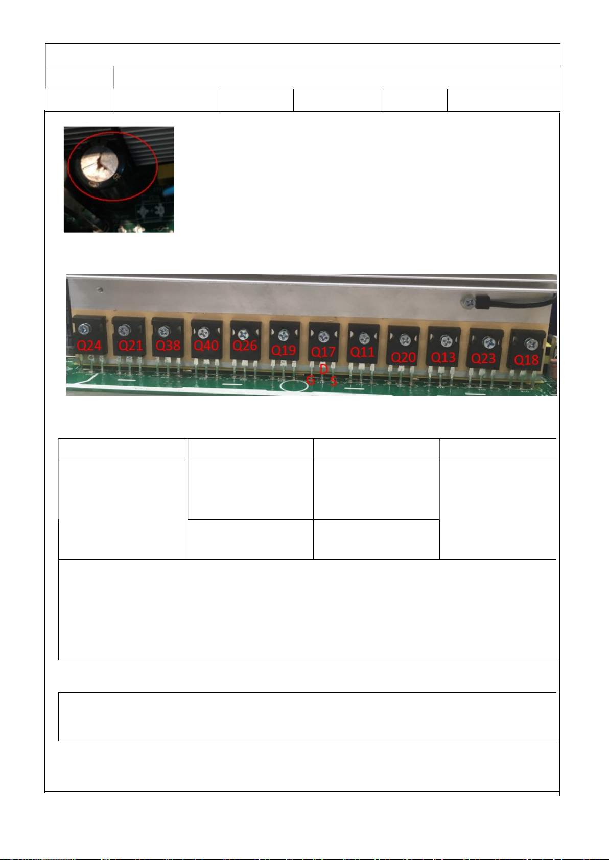
When open the top cover, please have a look first, are there any obviously damaged
parts?
When take the main board out, please have a look around, are there any obviously
damaged parts?
2.2.1. Not working at all/ No display
Description The inverter couldn’t startup completely.
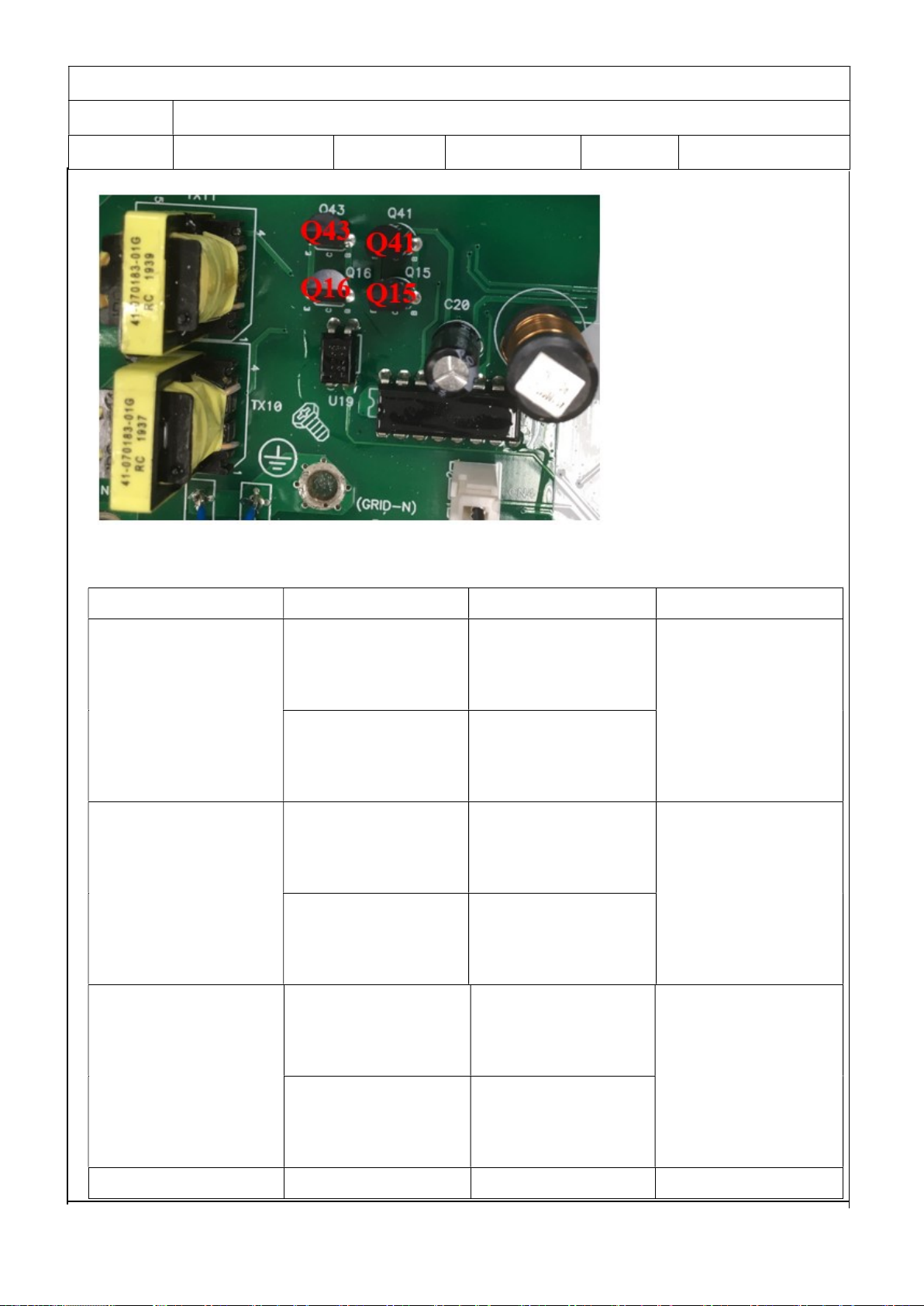
Possible reason 1. SPS module damaged.
How to check 1. Firstly, please measure the resistor between BAT+ and BAT-. If it is
not shorted, only connect the inverter with battery, and press “ON”
button, could the inverter startup? If not, please check the fan.
2. If the LCD couldn’t light up and fan doesn’t work, please disconnect
all the wires and open the top cover, and then take the main board
outside by following part 4.
3. Check the main board by following “3.5 and 3.6”
How to solve Repair the main or replace it directly.
2.2.2. 09 fault
Description Bus soft start fails.
Possible reason DC-DC module was damaged or BUS soft start module was damaged.
How to check 1. Check the main board by following“3.6; 3.7”;
2. Check the main board by following“3.1; 3.2; 3.3; 3.4”.
How to solve Repair the main board or replace it directly.
2.2.3. Warning
Description Battery couldn’t be detected.
Possible reason Wire connection or fuse was burnt.
How to check 1. Check the wire connection, the priority of the battery cable;
2. Check the main board by following “3.1”.
How to solve Repair the main board or replace it directly.

维修手册
专案名称:
Axpert Max 7200-48
专案编号:
P1911061 修订版次:
00 PAGE
V-RDP-004-73 A
2.3 Test step
After replacing all defected components, testing steps can be used to confirm the repair
result and the reliability of the Inverter.
Set up the testing system as below:
3. Checking and measuring guide
3.1 Check the battery side components on MAIN board
Fuse and capacitors
For Axpert Max-7200 FUCE

维修手册
专案名称:
Axpert Max 7200-48
专案编号:
P1911061 修订版次:
00 PAGE
V-RDP-004-73 A
Parts Attribute Reference values Failure status
F3 Resistor 0.2 ohm Open
For Axpert Max-7200 C8/C9/C12/C13/C18/C86: (6800uF 63V)
If the capacitors explode as below, they need to be replaced.

维修手册
专案名称:
Axpert Max 7200-48
专案编号:
P1911061 修订版次:
00 PAGE
V-RDP-004-73 A
Power devices
DC/DC MOSFET: Q24/Q21/Q38 & Q40/Q26/Q19 & Q17/Q11/Q20 & Q13/Q23/Q18
For Axpert Max-7200 ALL of the MOSFET are
(MOSFET IR/IRFP4668PBF 130A 200V N BULK TO-247)
Parts Attribute Reference values Failure status
IRFP4668PBF Resistor GS: 15.67k
GD: 510.0k
DS: 581.0k
Short or explosion
Diode SD: 0.556V
DS: OL
Note1: When you use the multimeter to measure the resistor of the transistor, because of
the capacitor in the circuit, it will cause the changing of the values when you measure the
DS and GD. So we recommend you measure the diode forward voltage of SD, and the
resistor of GS. These two values can reflect the situation of the transistor more correctly.
Note2: If one or more of them were damaged, please replace all of them.
3.1.1. Drivers (This part is only used for repair checking)
Note: Drivers usually need to be checked when users want to repair the boards. Because
when power devices were damaged, the high voltage will rush to driver circuit through the
gates of power devices.
The reference of the resistors list as below:
R76/R78/R80/R93/R92/R64

维修手册
专案名称:
Axpert Max 7200-48
专案编号:
P1911061 修订版次:
00 PAGE
V-RDP-004-73 A
R59/R41/R70/R52//R81/R62 All of the resistors are (22R 1206)
Use multimeter to measure each resistor, find the burnt resistors and replace them; don’t
need to replace them all.
Parts Attribute Reference values
Failure status
All: 22ohm Resistor 22 ohm Open or other values
If the resistors need to be replaced, please also check the driver transistors and control IC.
The Q46and Q48 are (TR UTC/2SC2655 2A 50V NPN TAP TO-92)
The Q47and Q49 are (TR UTC/2SA1020L-Y-T9N-B 2A 50V PNP TAP TO-92NL)

维修手册
专案名称:
Axpert Max 7200-48
专案编号:
P1911061 修订版次:
00 PAGE
V-RDP-004-73 A
The Q41and Q43 are (TR UTC/2SC2655 2A 50V NPN TAP TO-92)
The Q15and Q16 are (TR UTC/2SA1020L-Y-T9N-B 2A 50V PNP TAP TO-92NL)
Parts Attribute Reference values Failure status
Q46/Q48 Resistor BE: 429.6k
BC: 425.5k
EC: 15.7k
Short or explosion
Diode BE: 0.65V
BC: 0.65V
EC: 0.28V
Q41/Q43 Resistor BE: 428k
BC: 425k
EC: 15.5k
Short or explosion
Diode BE: 0.65V
BC: 0.65V
EC: 0.28V
Q47/Q49 Resistor BE: 431k
CB: 398k
CE: 1.07k
Short or explosion
Diode BE: 0.65V
CB: 0.63V
CE: 0.17V
Q15/Q16 Resistor BE: 430k Short or explosion

维修手册
专案名称:
Axpert Max 7200-48
专案编号:
P1911061 修订版次:
00 PAGE
V-RDP-004-73 A
CB: 393k
CE: 1.07k
Diode BE: 0.65V
CB: 0.60V
CE: 0.17V
The Q54and Q56 are (TR UTC/2SD1624 2A 50V NPN SOT-89)
The Q55and Q57 are (TR UTC/2SA1020 3A 50V PNP SOT-89)
Parts Attribute Reference values Failure status
Q54/Q56 Resistor BE: 15.87k
BC: 262.5k
CE: OL
Short or explosion
Diode BE: 0.63V
BC: 0.63V
CE: OL
Q55/Q57 Resistor BE: 15.87k
BC: OL
CE: 276.6k
Short or explosion
Diode BE: 0.63V
BC: OL
CE: 1.11V

维修手册
专案名称:
Axpert Max 7200-48
专案编号:
P1911061 修订版次:
00 PAGE
V-RDP-004-73 A
The Q51and Q52 are (TR UTC/2SD1624 2A 50V NPN SOT-89)
The Q50and Q53 are (TR UTC/2SA1020 3A 50V PNP SOT-89)
Parts Attribute Reference values Failure status
Q51/Q52 Resistor BE: 15.87k
BC: 262.5k
CE: OL
Short or explosion
Diode BE: 0.63V
BC: 0.63V
CE: OL
Q53/Q54 Resistor BE: 15.87k
BC: OL
CE: 276.6k
Short or explosion
Diode BE: 0.63V
BC: OL
CE: 1.11V
The Q60 and Q61 the MOSFET are (UT3404G 5.8A 30V NPN SOT-23 SMD)
Parts Attribute Reference values Failure status
Q60/Q61 Resistor GS: 4.123k Short or explosion

维修手册
专案名称:
Axpert Max 7200-48
专案编号:
P1911061 修订版次:
00 PAGE
V-RDP-004-73 A
GD: 9.58k
SD: 1.12k
Diode SD: 0.17V
DS: 1.33V
The U9 is (IC PWM CNTL ON/KA3525A)
Parts Attribute Reference values Failure status
U9 Resistor PIN13 TO PIN12: 8.8k
PIN11 TO PIN12: 432k
PIN14 TO PIN12: 432k
Short or explosion
3.2 Check the bus side components on MAIN board
Power devices
DC/DC IGBT: Q27/Q28/Q29/Q30/Q31/Q35/Q37/Q45
For Axpert Max-7200 ALL of the IGBTs are (IGBT ST/STGW60H65DFB 60A 650V N BULK TO-247)

维修手册
专案名称:
Axpert Max 7200-48
专案编号:
P1911061 修订版次:
00 PAGE
V-RDP-004-73 A
Parts Attribute Reference values Failure status
Q27/Q28/Q29/Q30
Q45/Q37/Q35/Q31
Resistor GE: 22.9 ohm
GC: 169.4k
EC: 169.1K
Short or explosion
Diode EC: 0.358V
CE: OL
Note1: When you use the multimeter to measure the resistor of the transistor, because of
the capacitor in the circuit, it will cause the changing of the values when you measure the
CE and GE. So we recommend you measure the diode forward voltage of EC, and the
resistor of GE. These two values can reflect the situation of the transistor more correctly.
Note2: If one or more of them were damaged, please replace all of them.
Drivers (This part is only used for repair checking)
Meanwhile, we also need to check the driver tubes of these power tubes.
R91/R103/R102/R300/R96/R106/R101/R238: (22R 1206)
R90/R105/R99/R302/R94/R109/R97/R239: (0R 1206)
D32/D60/D35/D62/D33/D61/D34/D66: (1N4148W 0.15A 75V SMD)
Parts Attribute Reference values Failure status
R91/R103/R102/R300/
R96/R106/R101/R238
Resistor 22 ohm Open or other
values
R90/R105/R99/R302
/R94/R109/R97/R239
Resistor 0 ohm

维修手册
专案名称:
Axpert Max 7200-48
专案编号:
P1911061 修订版次:
00 PAGE
V-RDP-004-73 A
D32/D60/D35/D62/
D33/D61/D34/D661
Resistor + to -: 270k
- to +: OL
Short or explosion
Diode + to -: 0.6V
- to +: OL
Note1: When test the diode; please remove the R90/R99/R94/R97 from the board, or the
test result is not right.
3.3 Check the buck circuit on MAIN board
Power devices
BUCK MOSFET and Diode:Q32/Q42/Q58
For Axpert Max-7200 the IGBTs Q32 /Q42 are (IGBT ST/STGW60H65DFB 60A 650V N BULK TO-247)
The Q58 is (APT/30DQ60BG 30A 600V UFST RAD TO-247 BULK)
Parts Attribute Reference values Failure status
Q32/Q42 Resistor GE:17.07k
GC: 209.3k
CE: OL
Short or explosion
Diode CE: OL
EC: 0.393V
Q58 Resistor + to -: 193.9k
- to +: OL
Diode + to -: 0.383V
- to +: OL

维修手册
专案名称:
Axpert Max 7200-48
专案编号:
P1911061 修订版次:
00 PAGE
V-RDP-004-73 A
Drivers (This part is only used for repair checking)
The R124/R128 are (10R 1206)
The R125/R134 are (47R 1206)
The D38/D40 are (1N4148W 0.15A 75V SMD)
Parts Attribute Reference values Failure status
R125/R134 Resistor 47 ohm Open or other values
R124/R128 Resistor 10 ohm
D38/D401 Resistor + to -: 240k
- to +: OL
Short or explosion
Diode + to -: 0.6V
- to +: OL
Note1: When test the diode; please remove the R124/R128 from the board, otherwise the
test result is not right.
3.4 Check the INV full bridge on MAIN board
Power devices
INV IGBT: QA1/QA2/QC1/QC2/QB2/QB3/QD2/QD3

维修手册
专案名称:
Axpert Max 7200-48
专案编号:
P1911061 修订版次:
00 PAGE
V-RDP-004-73 A
All of the IGBT are (STGW60H65DFB 60A 650V N BULK TO-247)
Parts Attribute Reference values Failure status
QA1/QA2/QC1/QC2/
QB2/QB3/QD2/QD3
Resistor GE: 17.59k
GC: 208.1k
EC: 183.7k
Short or explosion
Diode EC: 0.378V
CE: OL
Note1: If one or more of them were damaged, please replace all of them.
Drivers
R48/R53/R144/R153/R140/R218/R137/R229: (30R 1206)
Parts Attribute Reference values Failure status

维修手册
专案名称:
Axpert Max 7200-48
专案编号:
P1911061 修订版次:
00 PAGE
V-RDP-004-73 A
R48/R53/R144/R153/
R140/R218/R137/R229
Resistor 30 ohm Open or other values
Optocoupler: U1/U2/U3/U4/U12
ALL of the optocoupler are (TI/UCC23513DWYR 6/SOIC SMD)
Parts Attribute Reference values Failure status
U1/U2/U3/U4/U12
Diode PIN4 TO PIN5: 0.63V
PIN4 TO PIN6: 0.425V
Short or explosion
U2/U4/U12/ U1/U3
Resistor PIN4 TO PIN5: 198.4k
PIN4 TO PIN6: 160.7k
3.5 Check BATT and Main Power SPS on MAIN board
BATT Power SPS&Main Power SPS
The Q36 is (MOSFET IR/IRFP4227PBF 46A 200V N BULK TO-247)
The Q6 is (MOSFET IR/IRF840 8A 500V N BULK TO-220)
The U10 is (IC PWM CNTL ON/UC3845BNG DIP-8)
The D17 is (D IO/HER303 3A 200V UFST AXI DO-27 TAP)
The TX9 is (TX 5:5:5:3:1:6 FER EC35)
The TX2 is (TX 15:200:15 FER EEL16)
The R215 is (RES 3W 0.15 J N-IND
The R251 is (RES 2W 0.62 J RAD KINK N-IND TAP)
The D65 is (RHRP8120 8A 1200V )
The D70 is (ER802F 8A 200V)
The D67 is (ER802F 8A 200V)
The D54 is (ER802F 8A 200V)
The U20 is (IC LIN ST/L7912CV 3P/TO-220)
The U5 is (IC LIN ON/MC78M05CDTRKG DPAK-3 SMD)

维修手册
专案名称:
Axpert Max 7200-48
专案编号:
P1911061 修订版次:
00 PAGE
V-RDP-004-73 A
Parts Attribute
Reference values Failure status
Q36 Resistor
SD: 275K
SG: 16.4k
Short or explosion
Diode SD: 0.46V
SG: 0.65V
Q6 Resistor
SD: 275k
SG: 1.17k
Short or explosion
Diode SD: 0.46V
SG: 0.29V
U10 Diode PIN5 TO PIN7: 0.48V
PIN5 TO PIN6: 0.64V
Short or explosion

维修手册
专案名称:
Axpert Max 7200-48
专案编号:
P1911061 修订版次:
00 PAGE
V-RDP-004-73 A
D17 Diode + to -: 0.45V
- to +: OL
Short or explosion
TX9 Resistor
PIN1 TO PIN3: 0.2 ohm Short or other
values
TX2 Resistor
PIN2 TO PIN4: 2.7 ohm Short or other
values
R215 Resistor
0.15 ohm Open or other
values
R251 Resistor
0.62 ohm Open or other
values
D65 Diode + to -: 0.448V
- to +: OL
Short or explosion
D70 Diode + to -: 0.457V
- to +: OL
Short or explosion
D67 Diode + to -:0.458 V
- to +: OL
Short or explosion
D54 Diode + to -: 0.384V
- to +: OL
Short or explosion
U20 Diode PIN G TO PIN I: 1.96V
PIN G TO PIN O: 1.36V
Short or explosion
U5 Diode PIN G TO PIN I: 0.45V
PIN G TO PIN O: 0.98V
Short or explosion
3.6 Check AC SPS and PV SPS
The F1 is (FUSE 3A 250V )
The NTC1 is (NTC 10 OHM 3.0A)
The REC1 is (GBU4M 4A 1000V UFST)
The Q1 is (SPP11N80C3 11A 800V)
The TX1 is (TX 8:23:30:23 FER EER28)
The R21 is (RES 不燃性树脂型绕线 3W 0.47 J N-IND BULK)
The D6 is (RHRP860 8A 600V)
The Q2 is (SPP11N80C3 11A 800V)
The TX2 is (TX 8:23:30:23 FER EER28)
Table of contents
Other Axpert Inverter manuals