Ayre AX-7 User manual

Ayre AX-7
Owner’s Manual
Integrated Amplifier
A y r e


Table of
Contents
Welcome to Ayre . . . . . . . . . . . . . . . . . . . . . . . 2
Connections and Installation . . . . . . . . . . . . . . . . . . . . 3
Controls and Operation. . . . . . . . . . . . . . . . . . . . . 7
Numbers and Specifications . . . . . . . . . . . . . . . . . . 12
Statement of Warranty . . . . . . . . . . . . . . . . . . . . 13
A Place for Notes . . . . . . . . . . . . . . . . . . . . . . 16

Welcome to
Ayre
Please send in your warranty
registration card so we can
stay in contact with you.
Your Ayre AX-7 offers a significant advance in the
musical performance of high-fidelity equipment.
The warmth and immediacy of a live performance
are apparent from the first listening. The
combination of superb resolution and a natural,
relaxed quality will draw you into the music, time
and time again.
This level of performance has been implemented
using the highest level of workmanship and
materials. You can be assured that the Ayre AX-7
will provide you a lifetime of musical enjoyment.
2

Connections and
Installation
The Ayre AX-7 is easy to hook up and use. The
following guidelines will ensure that the installation
goes smoothly.
Location
Do not stack the Ayre AX-7
directly with other components,
as this may restrict the air
flow or induce hum into the
audio circuitry.
A good location for your integrated amplifier is near
eye level in an open-backed cabinet or on a shelf.
The Ayre AX-7 produces a moderate amount of heat
during operation. Be sure to provide at least three
inches (75 mm) of air space above the amplifier.
It is important to maintain an adequate
supply of air flow to avoid overheating
the amplifier.
The infrared beam will also
travel through glass.
The receiver for the infrared remote control is
mounted behind the display lens on the front panel.
A direct line of sight from the listening position
will ensure the maximum range. However, the beam
will also reflect off of most wall surfaces with a
reduced range.
3

Inputs
When you have a choice, a
balanced connection will offer
slightly higher sound quality
than an unbalanced
connection.
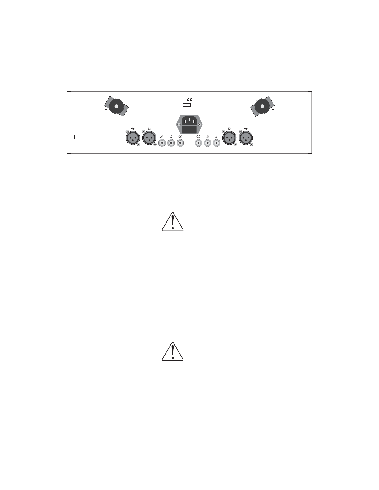
The Ayre AX-7 offers two pairs of balanced inputs
and two pairs of unbalanced inputs. Balanced
connections are made via three-pin XLR connectors,
while unbalanced connections are made via RCA
connectors.
The FET switches used in the input selector
circuitry offer transparent, noise-free switching,
with no moving parts. Please be aware that they can
be overloaded if the output voltage from the source
component is too high.
Do not use a source component that has
an output level greater than4Vrms
unbalanced, or 8 V rms balanced.
Using a source component with too great an output
level will cause distortion.
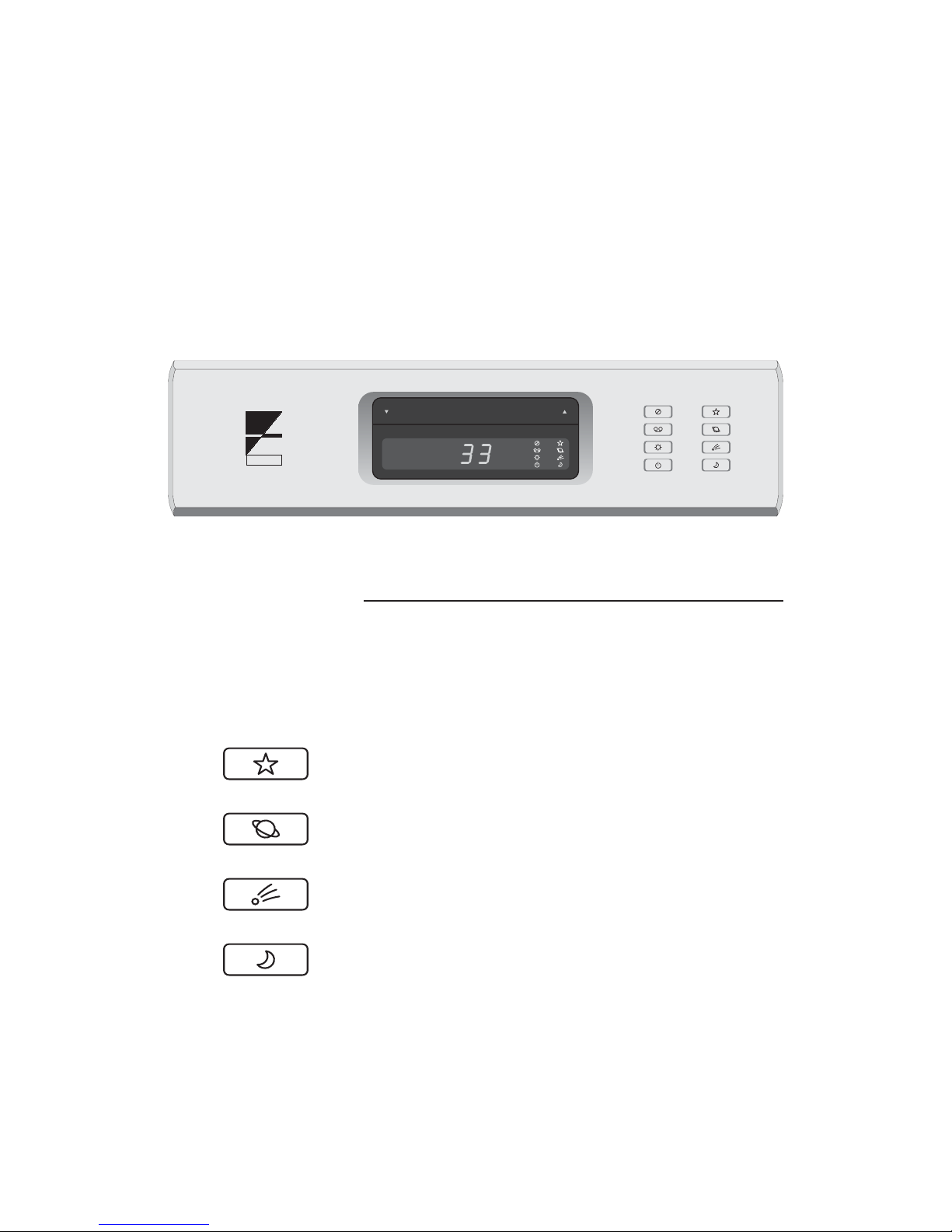
The input connectors on the
rear panel are labeled to
match the input selector
buttons.
In this modern era of diverse source components, it
has become impractical to pre-label the inputs with
the actual name of the source. Instead, the AX-7 has
simple icons that allow you to easily remember the
selector button associated with each source
component.
Tape Outputs
By connecting the “Tape Out” jacks on the rear of
the AX-7 to a recorder with analog inputs,
recordings may be made directly from the other
source components connected to your amplifier. The
4

tape outputs are switched on and off at the front
panel. Please refer to the section “Controls and
Operation” for further information.
If a recorder is not installed in
your system, the “Moon” input
performs exactly like the other
unbalanced inputs.
If you are connecting a recorder to your
system, be sure to connect its outputs to
the “Moon” input of the AX-7.
This will prevent the undesired possibility of
creating a feedback loop when making a recording.
Loudspeaker Outputs
The heavy-duty output
terminals of the Ayre AX-7
work best with speaker cables
using spade lugs.
The Ayre AX-7 drives the loudspeakers with
balanced outputs. Since none of the output
terminals are grounded, connecting any of them to
ground may result in damage to the amplifier.
Do not connect the loudspeaker
outputs to any speaker switch-box,
accessory, or test equipment that has a
common ground connection.
5
Volts
50/60 Hertz
300WMax
Tape Out
S2S2 S1S1
B2 B2
B1 B1
¡Attention — Balanced Outputs Do Not Connect Output Terminals to Ground!—
AX-7 Integrated Amplifier
A y r e
Boulder, Colorado USA
Right Channel Left Channel
S.N.

AC Power
The best sound quality is
normally achieved when the
AX-7 is plugged directly into
the wall outlet, without using
any power strips or power line
conditioners.
Connect the Ayre AX-7 to an unswitched power
source. When the unit is first connected to the AC
power, the input selector will default to “Star”, the
volume control will default to “11”, the display will
be set to “On”, and both the mute and record output
will be set to “Off”. Removing the AC power from
the unit will cause it to lose its memorized settings
and revert to the default settings.
6

Controls and
Operation
At the heart of the Ayre AX-7’s control system is a
sophisticated microprocessor. This microprocessor is
normally “asleep” and all digital systems are turned
off, including the master clock. When the
microprocessor receives a command, either from the
front panel or the remote control, it “wakes up” to
execute the command, and then immediately returns
to “sleep” mode. This system ensures noise-free
reproduction of music signals.
Volume Control
The volume level is changed
by pressing the black bar
above the front-panel display.
The remote control may also be
used to change the volume.
The Ayre AX-7’s exclusive volume control yields
superlative sonic performance. Field-Effect
Transistor (FET) switches combine with discrete
metal-film resistors to create a volume control with
crystal-clear transparency and no moving parts,
along with digital accuracy and repeatability. The
volume control comprises 66 individual levels, each
with a step size of 1.0 dB allowing for precise
selection of the desired volume setting.
When the unit is first connected to an AC power
source, the volume level defaults to “11”, a relatively
7

low setting. After that, the current volume setting is
retained in memory, and will remain constant when
changing inputs or when the unit is placed in
“Standby”.
Input Source Selection
The source component may also
be selected with the remote
control.
The input selector buttons are located at the right
side of the unit. Icons that match the connector
labels on the rear panel (Star, Planet, Comet, Moon)
are used to denote the inputs.
When the unit is first connected to an AC power
source, the “Star” input is selected by default. After
that, the current input selection is retained in
memory, even when the unit is placed in “Standby”.
The input selector utilizes sophisticated FET
switches. Both the signal and ground connections to
each source component are switched, so that any
un-selected components are completely disconnected
from the system. This avoids any problems with
undesired ground loops.
8
A y r e

Mute
Muting and un-muting may
also be performed with the
remote control.
The mute button provides an easy way to
temporarily turn the volume of the AX-7 to “zero”.
The current volume control setting is retained in
memory and appears on the display. When the unit
is placed in “Standby”, the mute function is reset.
Tape Output
The “Tape Output” function
does not operate on the “Moon”
input. This avoids the
undesired possibility of
creating a feedback loop.
When the “Tape Output” button is pressed, the
indicator will light up and the signal from the
currently selected source component will be routed
to the “Tape Out” connectors. This allows a
recording to be made.
Turn the “Tape Output” off, unless a recording is
being made. This will completely disconnect the
recorder from the AX-7 (including the ground
connection), avoiding the possibility of undesired
ground loops.
Display
The display may also be
turned on and off with the
remote control.
The display of the AX-7 may be turned off, if
desired. A single blue light indicates that the
display is turned off. When further commands are
received, either from the front-panel buttons or the
remote control, the display will be activated for a
few seconds to confirm the command, and then turn
off automatically. Pressing the “Display” button
again will turn the display on.
9

Standby
The standby function may
also be operated with the
remote control.
The Ayre AX-7 is very energy-efficient, and only
consumes about as much power as a standard light
bulb when playing. If you wish to further reduce
power consumption when not playing music, the
unit may be placed in standby mode. In standby
mode, the output stage is turned off and usage of
electricity is minimized.
Processor Pass-Through
When using the Ayre AX-7 in a surround-sound
system for home theater, it is desirable to use the
“Processor Pass-Through” mode. This mode allows
your two-channel music sources to be routed
directly through the AX-7, avoiding the sonic
degradation of most processors, and at the same time
allows the front two channels of the theater system
to integrate with the AX-7 with the touch of a
single button.
If you are using a surround-sound processor, connect
the front left and right outputs of the processor to
one of the inputs on the AX-7. Please note that the
AX-7 can accept either balanced or unbalanced
signals.
To activate the “Processor Pass-Through” mode for
that input, remove the AC power from the AX-7 for
at least 10 seconds. Then, while pressing the input
selector button corresponding to the chosen
surround-sound processor input, re-connect the AC
power.
10

The chosen input is now programmed for “Processor
Pass-Through” operation, disabling the now
redundant volume control of the AX-7. When that
input is selected, the preamplifier section of the
AX-7 is set to unity gain (0 dB), and the volume is
controlled directly from the surround-sound
processor. The volume indicator of the AX-7 will
display “PP” to show that the “Processor
Pass-Through” mode has been selected for that
input.
To clear the “Processor Pass-Through” mode from
an input and restore normal operation, remove the
AC power from the AX-7 for at least 10 seconds.
Then, while pressing the “Mute” button, re-connect
the AC power.
Break-In
100 to 500 hours of music
played through the system will
ensure full break-in.
Due to the manufacturing processes used for the
wires and capacitors, a break-in period is necessary
for the amplifier to reach its full sonic potential.
11
A y r e

Numbers and
Specifications
Power Output 60 watts per channel continuous into 8 ohms
120 watts per channel continuous into 4 ohms
Maximum Input Level 4 V rms – unbalanced inputs
8 V rms – balanced inputs
Input Impedance 20 kΩ– unbalanced inputs
40 kΩ– balanced inputs (20 kΩper phase)
XLR Input Polarity Pin 1 = Ground
Pin 2 = Non-inverting (Positive)
Pin 3 = Inverting (Negative)
Gain 35 dB (maximum, at volume level of “66”)
Frequency Response 2 Hz - 200 kHz
Power Consumption 20 watts in standby mode
70 watts in operating mode, no signal
Dimensions 17-¼" W x 13-¾" D x 4-¾" H
44 cm x 35 cm x 12 cm
Weight 25 pounds
11.5 kg
12

Statement of
Warranty
Please take a moment to fill
out and return the enclosed
warranty registration card.
Your Ayre AX-7 integrated amplifier is warranted
against defects in workmanship and materials for a
period of five years from the date of purchase. This
warranty is transferable to subsequent purchasers
within the original five-year period. All warranty
claims must be made through an authorized Ayre
dealer or distributor.
Warranty Statement
1. Ayre Acoustics, Inc. (Ayre) warrants the materials
and workmanship of this product for a period of five
years from date of first purchase. If any defects are
found in the materials or workmanship of this Ayre
product within the warranty period, the unit will be
repaired or replaced by Ayre or its authorized agent.
2. Purchaser must return the product, packed in the
original shipping carton, freight prepaid to:
Ayre Acoustics, Inc.
2300-B Central Avenue
Boulder, Colorado 80301
13

or to Ayre’s authorized agent.
3. Ayre reserves the right to inspect any product
that is the subject of any warranty claim prior to
repairing or replacing it. Final determination of
warranty coverage lies solely with Ayre.
Out-of-warranty claims will be billed for labor,
materials, return freight, and insurance as required.
Any product for which a warranty claim is accepted
will be returned to the purchaser and the cost of
shipping and insurance will be factory prepaid
within the boundaries of the USA. Units to be
shipped outside of the USA will be shipped freight
collect only.
4. Ayre strives to manufacture the finest possible
equipment, and therefore reserves the right to make
improvements on its products, without necessarily
assuming an obligation to retrofit such changes
upon its previously manufactured models.
5. The above warranty is the sole warranty given by
Ayre, and is in lieu of all other warranties. All
implied warranties, including warranties of
merchantability or fitness for any particular purpose
shall be strictly limited in duration to five years
from the date of original purchase, and upon
expiration of the warranty period (five years), Ayre
shall have no further obligation of any kind, whether
express or implied. Further, Ayre shall in no event
be obligated for any incidental or consequential
damages as a result of any defect or any warranty
claim, whether express or implied.
14

6. Ayre does not authorize any third party,
including any dealer or sales representative to
assume any liability of Ayre or make any warranty
for Ayre. The unit must not have been altered or
improperly serviced. The serial number on the unit
must not have been altered or removed.
7. Warranty registration cards must be completed
and mailed to Ayre within 30 days of purchase. Ayre
may, at its option, require from the purchaser valid
proof of purchase (dated copy or photocopy of
dealer's original invoice).
15

A Place for
Notes
16 Rev. 1.1


Ayre Acoustics, Inc.
2300-B Central Avenue
Boulder, Colorado 80301
www.ayre.com
+1-303-442-7300
Table of contents
Other Ayre Amplifier manuals