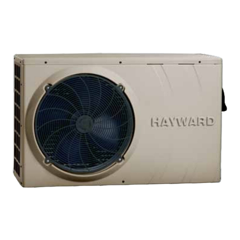
AZURO PASRW015-P-AI User manual

Type of refrigerant R32
Refrigerant quantity 0,32 kg
C02 equivalent o,216 t
GWP 675
PASRWOlS.P-AI
K
I
Code:8390026'l
SWIMMING POOL HEAT PUMP UNIT
lnstallation & lnstruction Manual
Type of refrigerant R32
Refrigerant quantity 0,50 kg
CO2 equivalent 0,338 t
GWP 675
PASRWO2O.P.AI

2.2 Dimensions for Swimming Pool Heat Pump Unit
3. lnstallation and Connection
3.1 lnstallation illustration
3.2 Swimming PoolHeat Pumps Location
1. Preface
2. Specifications
2.1 Performanc
3.3 How Close
3.4 Swimming
3.5 Swimming
CONTENTS
e Data of Swimming PoolHeat Pump Unit
to Your Pool?
Pool Heat Pumps Plumbing
Pool Heat Pumps ElectricalWiring
1
4
4
5
6
6
7
7
8
I
9
3.6 lnitialStart-up of the Unit
4. Use and Operation lnstruction of Wire Controller
4.1 Function of controller
4.2 Usage of wire controller
4.3 Parameter table
4.4 Malfunction Table " ' 1
4.5 Connection of PCB illustration 1
5. Maintenance and lnspection 1
6.Appendix 2
6.1 Cable specification
6.2 Comparison tableof refrigerant saturationtemperature
1
1
1
1
0
0
1
3
4
5
6
1
21
'22
I

PREFACE
o ln rrrrlor lrrIrrvrrlc ()rrr customerswith quality, reliability and vcr:iirlrlrly.llrl'. Iro(ltt(;t has
l,r,r'rr nr,rrlo ll',lttr lptorlttt;tron standards.This manual includes all llrr:trlr l',',,ttV
l[1,,|il,rll,'r,rlrilrrl lrr,,l,rll;rliorr,debugging, disCharging andmainteni]rrr:r: l'lr,r:;c rcildthis
Ir,il[r,rl , ,rrr:lrrlly lrillorilyorr r)l)cn ormAintain the unit.The manUfaCturcol llrir; protlttctwill
lll l,r, lrr,l,lrl,,l,r.r',llrll ll ,,orrrrnrr:i inirlred orthe unit isdamaged, as aresttlt oI
Iilrl.r,,l,"r lh,,l,rll,rll,,rr ,l',1'il1ltllil(l,or ilnnilcossilrymaintenance.ltisVitalthatthe
lil,lrr, ll,,I,, *,tllrlrr llrl,: rririlrtrl ,rtil,rrllrrrtilrllo;rl ;rlllimeS. TheUnit mUSt beinStalled by
rlrr,rltltr',1 lrrt r,'rrrtll
rr I lrr rilrll , iilr,,Il! I'il rrr1,,rl[,rll,y ,l[,rllllr,,l l[',l,rllIr r ilttltr, ;tttr;tttltttllrlT:ln aUthoriSed
(l Nrrlrrlr,rrrrli 1, 1111r1 rrl,rrr,rllrrllll,,l lrrr r,rtrllrlrrrtl 'r, rltrlltrl; l,,llrl rrrr ltltrrtt(llrlllttttr:ttttl
lrlrllril, y,r,,,l,rllrl lttlltl,, trt,tltt,tl
rr 11,,,, 11r'tiltltr', t,l,ilrlrrl,l,i|l.rlt, Irlrl,, rrrly
I ,rtlrrrri lrr r rrlrlrlywlllr llrr",,' t,', lttrrtr,ltrl,tllott'.wlll lttv,tllrl,llu lltrr w,ttt,ttlly
{) ',wlllilil][1] I'onl llrrrrll'ilrrrI lltrll ltrr,rl:.llril,,wlnIilin(l lo0lw,tlilr ailr(l l(!r:p:;lll(! ltttttlltlt;tltlttl
r rrrr',l,rrrl I or :,plillylro lnrl, llru rrrrloor lrral(:inr lrc I)i:;r;rr:tclylrl<ltlctt ttr s(]trti-lti(ldellto
r,urI ir luxurylrousc.
Our heat pumphas following characteristics:
1 Durable
The heatexchanger is madeof PVC &Titanium tubewhich can withstandprolonged
exposure to swimming pool water.
2 lnstallation flexibility
The unit can be inslalled outdoors.
3 Qttiet o[)cr;rlion
l lro rrrril r;orrrpr ir;c:; i ttr cllir:tcrrl rol:rr y/ :;r;r ollr:r)nrl)t ossor and a low-noise fan motor,
wlrtr lr r;rt.rt,rtlrrrr:, rl',rlrlrl olrot;tlton
,l /\r lv,rt rr lr I r r rr rl t llltr rr I
Ilril rilrll1il, 1ilr1,,.. [ilr ril ( rrrrl,illIr r.orrlrolltnrl,irllowirrg all operationparameterS tO be
.r',1 tll',,r,rll',r ,,l,rlr',r ,rrlrl rll:,II.rycrlotr lltr: I (llJwire controller.Remote controller canbe
r ltrr',rrtt .r,, ltlltltoolrll(llt
(J wAl{r'{lNr ;
l,o nol u:;orno;rr:; lo arcceleratethe defrosting processor to clean,
( )llr(!r llriur llloserecimmended by themanufacturer.
T'lrc irg>pliance shallbe stored ina room withoutcontinuously
operating ignition sources (for example:open flames, an
Operating gas applianceor an operatingelectric heater.)
Do not pierceor burn.
Be aware thatrefrigerants may notcontain an odour,
Appliance shall beinstalled,operated and storedin a ro()nrwrllr.r ll,,r .rto.r l.rtr;ct llt;ttt30m'.
NOTE Themanufacturer may provideothersuitable r-.x;rrngrlr",,,r rrr,ry lrrrrvrlo;rrltlitional
information about the refrigerant odour.
1. PREFACE
This appliance can be used by children aged from 8 years and above and persons
with reduced physical, sensory or mental capabilities or lack of experience and
knowledge if they have been given supervision or instructionconcerning use ofthe
appliance in a safe way and understand the hazards involved. Children shall not play with
the appliance. Cleaning and user maintenance shall not be made by children without
s u pe rvi si on.
lf the supplycord is damaged,it must bereplaced by themanufacturer, itsservice agent or
simi larly qualified persons in order to avoid a hazat d.
The appliance shallbe installed inaccordance with nationalwiring regulations.
Do not operateyour air conditionerin a wetroom such asa bathroom orlaundry room.
Before obtaining accessto terminals, allsupply circuits mustbe disconnected.
An all-pole disconnection device which has at least 3mm clearances in all poles , and
have a leakagecurrent that mayexceed 10mA, the residual current device(RCD) having
a rated residual operating current not exceeding 30mA, and disconnection must be
incorporated in thefixed wiring inaccordance with thewiring rules.
Do not use means to accelerate the defrosting process or to clean, other than those
recommended by the manufacturer
The appliance shallbe stored ina room withoutcontinuously operating ignitionsources (for
example: open flames, an operating gas appliance or an operating electric heater.)
Do not pierceor burn
Appliance shall beinstalled, operated andstored in aroom with afloor area largerthan 30
m2
Be aware thatrefrigerants may notcontain an odour.
The installation of pipe-work shall be kept to a minimum 30 m2
Spaces where refrigerantpipes shall becompliance with nationalgas regulations.
Servicing shall be performed only as recommended by the manufacturer.
The appliance shallbe stored ina well-ventilated areawhere the roomsize corresponds to
the room areaas specified foroperation.
All working procedure that affets safety means shall only be carried by competent persons.
Transport of equipment containing flammable refrigerants
Compliance with thetransport regulations
Marking of equipmentusing signs
Compliance with local regulations
Disposal of equipment using flammable refrigerants
Compliance with national regulations
Storage of equipment/appliances
The storage of equipment should bein accordance withthe manufacturer's instructions.
Storage of packed (unsold) equipment
Storage package protection should be constructed such that mechanical damage to the
equipment inside thepackage will notcause a leakofthe refrigerantcharge.
The maximum numberof pieces of equipment permitted to be stored togetherwill be
determined by local regulations.
e3
(,,
*
&
s
€,
2

I1. PREFACE
(.,rullotr & W;rttrittr;
I llrrr rlrll r .rr otrlylrr, tcp;tired byqualified installer centrepersonnel or ,rl,urllrori:io(l
rlr,,rlll llr I rlllrr,lt;ul(()l)
.' llrl',,r1,;,ll,rr!., I'i nolittlottrlorl lor ttscby persons (includingChildren)with roducodphysical
,,,,rLIrv ,,r ril,!rrl,rlr ,rl,,rl,illlrr",, ot l;rr:l<oI cxperience andknOWledge, unless theyhave been
!llv,,i| il1,,,rv1,.i,,il r'r lrr,,lrtrr llilil rotrr;filrirrr; USeof the applianCeby a personrespOnsible for
llrr,11 ',,,1,,1U llt I ttr,rlrl lrrrtl,r,l
r lrll,lr.'r'.lr,,ll,lI,r,'.11,',rvt,,r!'l lt lrr',rrrlllr,rl llrry rlotrol lllery Withthe appliance.
I l'1,,,r ,I rrr,rl.r, ,trril llr,rl llr,'[illl ,rIlI'r,wr,r( r,ililr'r ltrrn lt,tvc r;0rlrl t:arthine, othefwiSe may
,,ttt,,' r,lr" ltt,.rl,,1r,,, I'
'I ll llrr, ,rr1,;,ly ',rr,l l,,l,rrrr,rrlr,rl Il rrr.ll,,, rr,1rl,rr orl l,ylltl trr,rtrttl,rr ltttr,l otrrtl :;clvicc;tt;t:ttl
,,r ,,lrrrll,rrly,Ir,rlllllrllrrrt ,,'r lrr,'r'lrtr 1,, rrv',l,l,rlr,r,',rt,l
', lrrrilr ll\i.r -'lllr-'/'ll,/l t 1Wl I I )
I lrr,',yrrrllrlrlr,lrtr llrrl rr I rl'.,lrl rrttlw,t',ll lrttr llr,rlt , tttrrluttrrr,rllr 11rr,.r1,1,1,,,,,, r'tn(ltr:,llcl,
llr,rl llrl, ;rrrrrltrr l,,rl llro lrrlol tl', r',r'lrlltlrr, trrtt'.1 lrrrlr,rlrllr.rl',olr,u,tlrfly ltorttrlotnr::;ltr;
w,r.,lr', tilu..l lillirl\r,il lo,ttr,r yr.ltttr; r.r,nltil lrll r:lr:r:lilr.,rttrl flr:r:lt0iltr;(lcvt(io:i ()t lr;il1(l()(i
Irrr.k lo llrcrlr:;rlct wlr)n l)rt(;lr;lliitrl;;rn crlttivrrlcnl rrppliirtrr;c.
0. [Jirt:clive 2002/95/EC (ltoHs): l'his producI is conrpliantwith directive 2002/95/EC (RoHs)
concerning restrictions forthe use ofharmful substances in electric and electronicdevices.
7. Theunit CANNOTbe installed nearthe flammable gas.Once there isany leakage ofthe gas
, fire can be occur.
8. Make surethat there iscircuit breaker forthe unit, lackof circuit breaker can lead to
electrical shock orfire.
9. Theheat pump locatedinside the unitis equipped withan over-load protectionsystem. lt
does not allowfor the unitto start forat least 3minutes from aprevious stoppage.
10. The unit can onlybe repaired bythe qualified personnelof an installercenter or an
authorized dealer. ( for NorthAmerioa nrarkat)
11. lrl;l;rll;rliorr lnrr;l lrcprlrlorrrrr:rl irr ;rr;r:rrrrl;rrrr:r:willr tlrc NEC/CECt)y authorized persononly.
t lot N0tlltAtttilttr ;r ttrilkr,l t
1., U:il i;l,t,t,lY wiltl :i:illll/\lrl I I()l( /l,r
I I ( ,rrlt(,n lilrrrllilw,rll lril,rl rrrr lr,Irr;rrr, rrol :;rrilrrlrlr:Ior l)otirble waterconnection.
2.SPECIFICATIONS
2.1 Performance data of Swimming Pool Heat Pump Unit
.-" REFRIGERANT: R32
UNIT PASRWOl S-P-AI PASRWO2O-P-AI
Heating capacity
(27 t24.3"C )KW 5.0 8.0
Btu/h 1 7000 27200
Heatinq Power lnput KW 0.96 1.49
COP 5.20 5.37
Heating capacity
(24119"C )KW 4.37
Btu/h 14910 23444
Heating Power lnput KW 0.9'l 1.45
coP 4.80 4.83
Heating capacity
(15t12"C )KW 3.4 5.4
Btu/h 1 1600 18424
Heating Power lnput KW 0.9 1.42
COP 3.78 3.80
Power Supply 230Vl50Hz 230150H2
Compressor Quantity 11
uompressor rotary rota rv
Fan NumDer 11
Fan Power lnput W60 90
Fan Rotate Speed RPM 870 810
l-an Llrrectron horizontal horizontal
GWP 675 675
CO2 EQUIVALENT T0.216 0.338
Noise dB(A) 52 53
Water Connection mm 50 50
Water FlowVolume m'/h 2.2 3.5
Water Pressure Drop(max) kPa 2.5 2.5
Unit Net Dimensions(L/W/H) mm See the drawinq of the units
Unit Ship Dimensions(L/W/H mm See packat e lable
Net Weight kq see nameplate
Shipping Weight kg see packaqe label
Heating: Outdoor airtemp: 27C124.3'C, lnlet watertemp:26C
Outdoor air temp: 24Cl1 9C, lnlet watertemp:26C
Outdoor air temp:'l 5C l 12'C, lnlet watertemp:26C
Operating range:
Am bient temperatu re :-7-43C
Water temperature:9-40 C
34

I2.SPECIFICATIONS
2.2 The dlmensions for Swimming Pool Heat Pump Unit
Modol: PASRW015-P-A| unit,
,l rrL
,lffiffil]||.|,ilil'''.,,,',]][m
Model: PASRW020-P-Al
lrlr0
t'
1._L q
llr----..-...--..-l
lr-----...---.--.h
lr-------rI
l-j
ts
unit: mm
560
ih
lr:-l
-l lr rl
allr--_--.------..--lll
..,1|---P
ll...--.--...-l
3. I NSTALLATION AN D CONN ECTION
3. 1 lnstallation illustration
lnstallation items:
The factory only provides the main unit and the water unit;the other items in the illustration
are necessary spare parts for thewater system ,thatprovided by usersor the installer.
Attention:
Please follow thesesteps when usingfor the firsttime
1.Open valve and charge water.
2.Make sure thatthe pump andthe water-in pipehave been filledwith water.
3.Close the valve and start the unit.
ATTN: lt is necessarythat the water-inpipe is higherthan the poolsurface.
The schematicdiagram is forreference only. Please checkthe water inlet/outleilabel on the
heat pump while plumbing installation.
The schematicdiagram is forreference only. Please checkthe water inlet/outletlabel on the
heat pump while plumbing installation.
The controller ismounted on thewall.
Water inlet Sand filter Waler pump
(or other type filter)
m
56

3.INSTALLATION AND CONNEC I I()N
3.2 Swimming Pool Heat Pumps Location
The unit willperform well inany outdoor locationprovided that thofollowlng threo factorsare
presented:
1. Fresh Air - 2, Electricity - 3. Pool filter piping
The unit maybe installed virtuallyanywhere outdoors. Forindoor pools pleaseconsult the
supplier. Unlikea gas heater, it hasno.draft orpilot light problemin a windyarea.
DO NOTplace the unitin an enclosedarea with alimited air volume,where the uniis
cilachargo alr wlll be ro-circulated.
DO NOTplscs th6 unltto shrubs whlchcan block airinlet. These locations deny theunit of a
0ontlnuour rourco olfrosh alr whlch reducss it efliclency and mayprevent adequate heat
dlllvrry,
.l ll llow Olost: Io Your Pool?
Norrrirlly, tl)o l)ool hr::rtputnp is installedwithin 7.5 metresof the pool.The longer the
rlisl;rrrr:c lrorrr ilrr:pool, the greaterthe heat lossfrom the piping.Forthe mostpart,the piping
i:; lruriC<1. Therefore, the heatloss is minimalfor runs of up to15 meters('l 5meters to andfrom
thcpump=30meters total),unlessthegroundiswetorthewatertableishigh.Averyrough
estimate of heat loss per 30 meters is 0.6 kW-hour,(2000BTU)for every 5 C difference in
temperature between thepool water andthe ground surroundingthe pipe, whichtranslates to
about 3% to5% increase inrun time.
3. I NSTALLATION AN D CON N ECTION
3.4 Swimming Pool Heat Pumps Plumbing
The Swimming PoolHeat Pumps exclusive rated flow titanium heat exchanger requires no
special plumbing arrangementsexcept bypass(please setthe flow rateaccording to the
nameplate). The water pressure drop is less than 10kPa at max. Flow rate. Sincethere is no
residual heat orflame Temperatures, The unit does notneed copper heatsink piping. PVC
pipe can berun straight intothe unit.
Location: Connect the unit in the pool pump discharge (return) line downstream of all filter
and pool pumps,and upstream ofany chlorinators, ozonatorsor chemical pumps.
Standard model haveslip glue fittingswhich accept 32mmor 50 mm PVC pipe for
connection to thepool or spafiltration piping. Byusing a 50NB to 40NByou can plumb40NB
Give serious considerationto adding aquick coupler fittingat the unitinlet and outletto allow
easy dralning of unit for winterizingand to provideeasier access shouldservicing be
required.
----->To pool
PVC COUPLER
RECOMMENDED(Provided)
From pump
CONDENSATION
DRAIN
BARB FTG
Condensation: Since theHeat pump coolsdown the airabout 4 -5C, water maycondense on
the fins ofthe horseshoe shapedevaporator. lf the relative humidityis very high,this could
be as muchas several litresan hour.The waterwill run downthe fins inioihe basepan and
drain out throughthe barbed plasticcondensation drain fittingon the sideof the basepan.
This fitting ls designed to accept 20mm clear vinyltubing which can be pushed on by hand
and run toa suitable drain.lt is easyto mistake thecondensation for awater leak insidethe
unit.
NB: Aquick way toverify that thewater is condensation is to shutoff the unit and keepthe
pool pump running.lf the waterstops running outof the basepan, it is condensation.AN
EVEN QUICKER WAYIS toTEST THEDRAIN WATER FOR CHLORINE. if theis no chlorine
present, then it's condensation.
B

3. I NSTALLATION AN D CONN ECTION
3.5 Swimming Pool Heat Pumps Electrical Wiring
NOTE: Althoughthe unit heatexchanger is electricallyisolated from therest of theunit, it
elmply provents theflow of electricityto or fromthe pool water. Grounding theunit is still
roqulrod to protectyou against shortcircuits inside the unit. Bonding isalso required.
Thc unlt haaa aeparate molded-injunction box witha standard electricalconduit nipple
e lrcady ln place.Juet remov€ thescrews and thefront panel, feedyour supply linesin
through tho condultnlpple and wlre-nutthe electric supplywires to thethree connections
elrcldy ln tholunctlon box (fourconn€ctions if three phase). To complete electrical hookup,
oonnoct Hort Pumpby cloctrlcal condult, UF cable orother suitable meansas specified (as
pormlttrrl hy localaloclrlcnl authorltlos) toa dodlcatodAC power supplybranch circuit
oqulppöd wlth thopropor olrcult broakor, dlsconnoct ortimo dolay fuseprotection.
Dlroonnoct -A dlrconnoolmoona (clrcult broakor, fused orun-fused swltch) shouldbe
located wlthln clghtof and readllyaccoaelblo from the unlt, Thls ls common practiceon
comrnorclal and resldontlalalr condltlonors andhoat pumps, ltprevonts remotely-energizing
unattended equipment and permits turning off power atthe unit while the unit is being
serviced.
3.6 lnitial start-up of the Unit
NOTE- ln orderfor the unitto heat thepool or spa,the filter pumpmust be runningto
circulate water throughthe heat exchanger.
Start up Procedure- Afterinstallation is completed,you should followthese steps:
1. Turn on your filterpump. Check forwater leaks and verify flow toand from the pool.
2, Turn on the electricalpower supply lo the unit, then press the key ON/OFF of wire
controller, ltshould start in several seconds.
3. Afterrunning a fewminutes make surethe air leavingthe top(side) ofthe unit is
cooler(Between 5-"1 0 C)
4. Wlth thounlt oparatlng turnthe filter pumpoff. Theunit should alsoturn off automatically,
5. Allowtho unlt andpool pump torun 24 hoursper day untildesired pool watertemperature
lg roached, Whon tho water-ln temperature reaches this setting, the unit willslow down fora
porlod of tlmo,lf tho tomperature ls maintained for45 minutes the unit will turn off. The unit
wlll now outomatlcallyrestart (as longas your pool pump is running)whenthe pool
lemperature drops more than 0.2 below set temperature.
Time Delay- The unit is equipped with a 3 minute built-in solid state restart delay included to
protoct control circuitcomponents and toeliminate restart cyclingand contactor chatter.
This time delaywill automatically restartthe unit approximately3 minutes aftereach control
circuit interruption. Evena brief powerinterruption will activatethe solid state3 minute
restart delay and prevent the unitfrom starting untilthe 5 minutecountdown is completed.
I
4.Use and Operation lnstruction of Wire Controller
4.'l . Function of wire controller
LED display
Down Up
Key Key name Key function
oON/OFF Press this keyto turn on/ofr the unit
^Up Press this keyto select theupward option
or increase the parameter value.
VDown Press this keyto select thedownward
option or decreasethe parameter value
10

4.Use and Ooeration lnstruction of Wire Controller
4.2 Usage of wire controller
4.2.1 Turn ON/OFF the unit
When the unitis off, press the tey " O " and hold on for 0,5s to turnon the unit;
When the unitis on, pressthe r."y " O " and hold on for 0.5s to turnoff theunit;
Press "O "
for 0.5s
---.*------.---->
Press "O "
for 0.5s
Press " A "
nr"Y"
Heating/Cooling
actual water Temp.
Standby interface Running interface
2.2 Setting temperature
ln the runninginterface, press ",1 " or "Y" then the currentmode target-temperature
flashes, then press " A " to increase thetemp.value, or press " Y " to decrease it.
Press " $ " will not save settingparåmeter but backto the maininterface;
Attention: lf there isno operation for5s, system would rememberparameter setting and
back to the main interface"
ln the main interface, press Z "L" tor 2s you can see the outlet temp.The parameteris
then flashed andthe display isback to themain interface after10s.
iåI
Heating/Cooling
Targettemp.
- Heating/Cooling
Targettemp.
Press t
"2s \\\ Press
System will "uu" user'i'\
setting and return back \
to main interface ifthere \
is no operation inss. \
f^
Running interface
Running interface
11
- outlet temp
12
4.Use and Operation lnstruction of Wire Controller
4.2.3 Mode switch
ln the maininterface,press "4" and "Y" for o.5s canset the mode,press "L"
or 'Y" to change ihecurrent mode,you canswitch differentmodes of colling,
heating and automode.
lf there isno operation forSs system willsave the currentmode änd backto the main
interface, press "()" can not savesetting
The modes switchingis useless of the unit youbuy is singel-cold/single-heatunit
The unit working mode
r
Press "A" and "Y"
--_______--__--.
Press "A"
4.2.4 Keyboard lock
To avoid mis-operations, please lock thecontroller after parametersetting.
Atthemain interface, pressing " $ " for 5 seconds,whenhearing one sound,
the keyboard islocked,
When the keyboardis locked, pressing " $ " tor 5 seconds, when hearing onesound,
the keyboard lockis open.
NOTES: When theunit is inalarming state, thekey lock canbe removed automaticly.
"'"'l
..]]l]l]]i]]ll§ll{tllliillll1iill]tilt]itl]ttl';]r]
f:Tr
lwl I Å l'
IYt t&l
I 1,,""""'"

4.Use and Operation lnstruction of \Alire tonlroller
4.2.5 Malfunction display
There will bemalfunction code showingon the controllerscreen when relativemalfunction
occurs.
lf there aremore than onemalfuctions occurs atthe same time,you can checkthe current
error codes listby pressing "4 " or "Y " Xey.
You can refer tothe malfunction tableto find outthe failure cause and solution.
For example:
Water inlettemp. Sensor failure
4.3 Parametertable
Meaning Defa u lt Remarks
Set-point of colling mode target temp. 27'C A.justable
Set-point of heating mode target temp. 27'C Ajustable
Set-point of automode target temp. 27'C Ajustable
13 14
4.Use and Operation lnstruction of Wire Controller
4.4.Malfunction Table
The common failurecause and solution.
Malfunction Canse Solution
Water lnlet temp. Sensor failure P01 The water inlei temp.Sensor
is open or shortcircuit lheck or chanqe thewaler
nlet temp. Sensor
Water oullet lemp. Sensor failure P02 The waler outlet tomp,sensor
is open or shortcircuit Check or change lhewater
oullet lemp. Sensor
Ambient temp. Sensor failure P04 The ambient temp. sensor
is open or shortcircurt Check or change the
amb ent temp. Sensor
Pipe temp. Sensor failure P05 The pipe temp.sensor is
open o, short circuit Check or change thepipe temp. Sensor
Evaporator temp.Sensor tailure P07 The evaporalor lemp. Sensor
is open or shorlcircuil Check or change the
evaporator lemp. Sensor
High pressure prolect E01 The exhausl pressure ishigh ,
high pressure swjtch aclion Check high pressure switch
and cooling return circuil
Low pressure protecl EA2 The suction pressuro islow,
Low pressure switch aclion Check low pressure swilchand
cooling return circuit
Flow switch failure E03 No water or litterwater
in water syslem Check the flow volum6,wäler
pump is failure ornot
Temp. istoo much dilf6rent
belween waier-inlet aod oullel E06 Water flow volumenot enough,
Water system pressurediffeaence is small Check the flow volume,water
syslem is jammed ornol
Antil.eezing !nder cooling modc EO7 Waler flow volumenot enough Check the flow volume,water
system is jammed ornot
The primary ant'-freezing
proteclion starl. E19 Ambieni lemperalure is toolow
The second anti-fr6ezing
protection start E29 Ambient lemperaturo io toolow
Communication failure E08 Comorunication failure between
remote wire controller andmain board Check the wire connection belween
remote wire con{rollor andmain board

4.Use and Ooeration lnstruction of Wire Controller
4.5.Connection of PCB illustration
4.5.1 Connections explanation:
No. Svmbol Meaninq
I OUTl Compressor of system 1 (220-230VAC)
2OUT2 Water pump (220-230VAC)
3OUT3 4wayvalve (220-230VAC)
4OUT4 Hiqh speed offan motor (220-230VAC)
5OUT5 Low speed offan motor (220-23OVAC)
6AC-N Neutral wire
7\ET GND 12 Wire controller
DIOl GND On/Off Switch(input)(no use)
o DIO2 GND Flow switch (input)( normal close)
10 DIO3 GND Low pressure protect
11 DI04 GND Hiqh pressure protect
12 DI05 GND No use
13 DIO6 GND No use
14 AIOl GND Suction temp.(input)
15 AI02 GND Water in temp.(input)
16 AI03 GND Water outtemp.(input)
17 AIO4 GND Temp. Of coil (input)
18 AIO5 GND Ambient temp.(input)
10 A106 GND Adjustable fan speed/Exhausttemperature
cN1 Primarv transformer
21 CN2 Secondary transformer
22 cN6 Without use
l3 CN1 9 Electronic expansion valve
24 5VCN16GNt Flow meter
15 16
5. MAINTENANCE AND INSPECTION
66Check the watersupply device andthe release often.Youshould avoid thecondition of no
water or airentering into system,as this willinfluence unit's performanceand reliability.
Youshould clear thepool/spa filter regularly to avoid damageto the unitas a resultof the
dirty of clogged filter.
&The area aroundthe unit shouldbe dry, clean andwell ventilated, Cleanthe side heating
exchanger regularly tomaintain good heatexchange as conserveenergy .
&The operation pressureof the refrigerantsysiem should onlybe serviced bya certified
technician.
6pCheck the powersupply and cableconnection often,.Should theunit begin tooperate
abnormally, switch lt of and contactthe qualified technician.
6Discharge all waterin the waterpump and watersystem ,so that freezing of thewater in the
pump or watersystem does notoccur. Youshould discharge thewaier at thebottom of
water pump ifthe unit willnot be usedfor an extendedperiod of time.Youshould check the
unitthoroughly andfill thesystemwithwaterfullybeforeusingitforthefirsttimeaftera
prolonged period ofno usage.
@Checks to thearea
Prior to beginningwork on systemscontaining flammable refrigerants, safety checks are
necessary to ensurethat the riskof ignition isminimised. For repairto the refrigerating
system, the followingprecautions shall becomplied with priorto conducting workon the
system.
&Work procedure
Work shallbe undertaken undera controlled procedureso as tominimise the riskof a
flammable gas orvapour being presentwhile the workis being performed.
@ General work area
All maintenance staff and othersworking in thelocal area shallbe instructed onthe nature
of work beingcarried out. Work in confinedspaces shall beavoided. Thearea around the
workspace shall besectioned off. Ensure that theconditions within thearea have been
made safe bycontrol of flammablematerial.
@Checking for presenceof refrigerant
The area shallbe checked withan appropriate refrigerantdetector prior toand during work,
to ensure thetechnician is aware of potentially flammable atmospheres. Ensure thatthe
leak detection equipmentbeing used issuitable for usewith flammable refrigerants, i.e.
non-sparking, adequately sealed or intrinsically safe.
6 Presence of fire extinguisher
lf any hotwork is tobe conducted onthe refrigeratlon equipmentor any associatedparts,
appropriate fire extinguishingequipment shall beavailable to hand. Have a drypowder or
C02 fire extinguisheradjacent to thecharging area.
, o.oNo40<o6o@o
litt2o2aza2oza 2oZ
.' z o o o o o o o o o o o ö o

5. MAINTENANCE AND INSPECTION
§åNo ignition sources
No person carrying out work in relation to a refrigeration system which involves exposing
any pipe workthat contains orhas contained flammablerefrigerant shall useany sources
of ignition insuch a mannerthat it maylead to therisk of fireor explosion.All possible
ignition sources, including cigarette smoking, should be kept suficiently far awayfrom the
site of installation, repairing, removing anddisposal, during whichflammable refrigerant
can possibly bereleased to thesurrounding space. Priorto work takingplace, the area
around the equipmentis to besurveyed to makesure that thereare no flammablehazards
or ignition risks. "No Smoking" signs shall bedisplayed.
&Ventilated area
Ensure that thearea is inthe open orthat it isadequately ventilated beforebreaking into
the system orconducting any hotwork. Adegree ofventilationshall continue duringthe
period that thework is carriedout. Theventilation should safelydisperse any released
refrigerant and preferablyexpel it externallyinto the atmosphere.
& Checks to the refrigeration equipment
Where electrical componentsare being changed,they shall befit for thepurpose and tothe
correct specification.At all timesthe manufacturer's maintenanceand service guidelines
shall be followed.lf in doubtconsult the manufacturer'stechnical department for
assistance.
The following checksshall be appliedto installations usingflammable refrigerants:
The chargesize is inaccordance with theroom size withinwhich the refrigerantcontaining
parts are installed;
The ventilationmachinery and outletsare operating adequatelyand are notobstructed;
lf an indirectrefrigerating circuit isbeing used, thesecondary circuit shall be checked for
the presence of refrigerant;
Marking to theequipment continues tobe visible andlegible. Markings andsigns that are
illegible shall becorrected;
Reirigeration pipe orcomponents are installedin a positionwhere they areunlikely to be
exposed to anysubstance which maycorrode refrigerant containing components, unless
the components areconstructed of materialswhich are inherentlyresistant to being
corroded or aresuitably protected againstbeing so corroded.
3 Checks to electricaldevices
Repair and maintenanceto electrical componentsshall include initialsafety checks and
component inspection procedures. lf a faultexists that couldcompromise safety, then no
electrical supply shallbe connected tothe circuit untilit is satisfactorilydealt with. lf the
fault cannot becorrected immediately butit is necessaryto continue operation,an
adequate temporary solutionshall be used.This shall be reported tothe owner ofthe
equipment so allparties are advised.
lnitial safety checks shall include:
. Thatcapacitors are discharged:this shall bedone in asafe manner toavoid possibility of
sparking;
. Thatthere no liveelectrical components andwiring are exposedwhile charging,
recovering or purgingthe system;
. Thatthere is continuityof earth bonding.
17 18
5. MAINTENANCE AND INSPECTION
@ Repairs to sealed components
1) During repairsto sealed components,all electrical suppliesshall be disconnectedfrom
the equipment being worked upon priorto any removalof sealed covers, etc. lf it
isabsolutely necessary tohave an electricalsupply to equipmentduring servicing, thena
permanently operating form of leak detection shall be located at the mostcritical point to
warn of a potentially hazardous situation.
2) Particular attentionshall be paidto the followingto ensure thatby working onelectrical
components, ihe casing is not altered in such away that the level of protection is affected.
This shall include damage to cables, excessive number of connections, terminals not made
to original specification, damage to seals, incorrect fitting of glands, etc.
& Ensure that apparatus is mounted securely.
Ensure that sealsor sealing materialshave not degradedsuch that theyno longer serve
the purpose of preventing the ingressof flammable atmospheres. Replacement parts shall
be in accordancewith the manufacturer'sspecifications.
N OTE: The use of silicon sealant may inhibit the effectiveness of some types of leak
detection equipment. lntrinsicallysafe components donot have tobe isolated priorto
working on them.
@ Repair to intrinsicallysafe components
Do not applyany permanent inductiveor capacitance loadsto the circuitwithout ensuring
that this willnot exceed the permissible voltage andcurrent permitted forthe equipment in
use.
lntrinsically safe componentsare the onlytypes that canbe worked onwhile live inthe
presence of aflammable atmosphere. The test apparatusshall be atthe correct rating.
Replace components onlywith parts specified by the manufacturer. Other parts may result
in the ignitionof refrigerant inthe atmosphere froma leak.
@ Cabling
Check that cablingwill not besubject to wear, corrosion, excessivepressure, vibration,
sharp edges orany other adverse environmental effects. The check shall also take into
account the efiects of agingor continual vibrationfrom sources suchas compressors or
fans.
§ Detection of flammable refrigerants
Under no circumstancesshall potential sourcesof ignition beused in thesearching for or
detection of refrigerantleaks. Ahalide torch (orany other detectorusing a nakedflame)
shall not be used.
6 Leak detection methods
The following leakdetection methods aredeemed acceptable forsystems containing
flammable refrigerants.
Electronicleakdetectorsshall beusedtodetectflammablerefrigerants,butthesensitivity
may not beadequate, or mayneed re-calibration. (Detectionequipment shall becalibrated
in a refrigerant-freearea.) Ensure thatthe detector isnot a potentialsource of ignitionand
is suitable forthe refrigerant used.Leak detection equipmentshall be setat a percentage
of the LFLof the refrigerantand shall becalibrated totherefrigerantemployed andthe
appropriate percentage of gas (25 %maximum) is confirmed.
Leak detection fluidsare suitable foruse with mostrefrigerants but the use of detergents
containing chlorine shall be avoided as the chlorine may react with the refrigerant and
corrode the copper pipe-work.
lf a leakis suspected, allnaked flames shallbe removed/ extinguished.
lf a leakageof refrigerant isfound which requiresbrazing, all ofthe refrigerant shallbe
recovered from thesystem, or isolated(by means ofshut offvalves) in apart ofthesystem
remote from theleak. Oxygen freenitrogen (OFN) shallthen be purgedthrough the system
both before andduring the brazingprocess.

1
I
l
5. MAINTENANCE AND INSPECTION
&; Removal and evacuation
When breaking intothe refrigerant circuitto make repairs or for anyother purpose
conventional procedures shallbe used. However, it isimportant that bestpractice is
followed since flammabilityis a consideration.The following procedure shall beadhered to:
. Remove refrigerant;
. Purge thecircuit with inertgas;
. Evacuate;
. Purge againwith inert gas;
. Open the circuit by cutting or brazing.
The refrigerant chargeshall be recoveredinto the correctrecovery cylinders.The system
shall be "flushed"with OFN torender the unitsafe. This process may needto be repeated
several times. Compressed air or oxygen shall not be used for thistask.
Flushing shall beachieved by breakingthe vacuum inthe system withOFN and continuing
to fill untilthe working pressureis achieved, thenventing to atmosphere,and finally pulling
down to avacuum. This process shall berepeated until norefrigerant is withinthe system.
When the final OFN charge isused, the systemshall be venteddown to atmospheric
pressure to enablework to takeplace. Thisoperation is absolutelyvital if brazing
operations on the pipe-work are totake place.
Ensure that theoutlet for thevacuum pump isnot close toany ignition sourcesand there is
ventilation available working on them.
§i Labeiling
Equipment shall belabelled stating thatit has beende-commissioned and emptiedof
refrigerant. The label shall bedated and signed. Ensure that there are labels on the
equipment stating theequipment contains flammablerefrigerant.
Recovery
When removing refrigerantfrom a system,eitherfor servicingor decommissioning, itis
recommended good practicethat all refrigerantsare removed safely.
When transferring refrigerantinto cylinders, ensurethat only appropriaterefrigerant
recovery cylinders areemployed. Ensure thatthe correct numberof cylinders forholding
the total systemcharge is available.All cylindersto be usedare designated forthe
recovered refrigerant and labelled for that refrigerant (i.e. special cylinders for the recovery
of refrigerant). Cylindersshall be completewith pressure reliefvalve and associatedshut-
off valvesin good workingorder. Emptyrecovery cylinders areevacuated and, if possible,
cooled before recoveryoccurs.
The recovery equipmentshall be ingood working orderwith a setof instructions
concerning the equipmentthat is athand and shallbe suitable forthe recovery of
flammable refrigerants. lnaddition, a setof calibrated weighingscales shall beavailable
and in goodworking order. Hoses shall becomplete with leak-freedisconnect couplings
and in goodcondition. Before usingthe recovery machine,check that itis in satisfactory
working order, has been properly maintained and thatany associated electrical
components are sealedto prevent ignitionin the eventof a refrigerantrelease. Consult
manufacturer if in doubt.
The recovered refrigerantshall be returned to the refrigerantsupplier in the correct
recovery cylinder, and the relevantWaste Transfer Note arranged. Do not mixrefrigerants
in recovery unitsand especially notin cylinders.
lf compressors orcompressor oils areto be removed, ensure that theyhave been
evacuated to anacceptable level tomake certain thatflammable refrigerant doesnot
remain within the lubricant. The evacuation process shall be carried out prior to returning
the compressor tothe suppliers. Onlyelectric heating tothe compressor bodyshall be
employed to acceleratethis process. Whenoil is drainedfrom a system,it shall becarried
out safely.
19 20
5. MAINTENANCE AND INSPECTION
€! Decommissioning
Before carrying outthis procedure, itis essentialthatthe technician iscompletely familiirr
with the equipmentand all itsdetail. lt isrecommended good practicethat all refrigerantr;
are recovered safely. Priortothe task beingcarried out, anoil and refrigerantsample slr;rl
be taken incase analysis isrequired prior tore-use of reclaimedrefrigerant. lt isessentiirl
that electrical poweris available beforethe task iscommenced.
a) Become familiarwith the equipmentand its operation.
b) lsolate system electrically.
c) Before attemptingthe procedure ensurethat:
. Mechanical handling equipment is available, if required, forhandling refrigerant cylin<lr:r
. Allpersonal protective equipmentis available andbeing used correctly;
. The recovery process issupervised at alltimes by acompetent person;
. Recovery equipmentand cylinders conformto the appropriatestandards.
d) Pump down refrigerant system, if possible.
e) lf avacuum is notpossible, make amanifold so thatrefrigerant can beremoved from
various parts ofthe system.
f) Make surethat cylinder issituated on thescales before recoverytakes place.
g) Start therecovery machine andoperate in accordancewith manufacturer's instruction:;
h) Do notoverfill cylinders. (Nomore than 80% volume liquidcharge).
i) Do notexceed the maximumworking pressure ofthe cylinder,even temporarily.
j)When thecylinders have beenfilled correctly andthe process completed,make sure lhir
the cylinders andthe equipment areremoved from sitepromptly and allisolation valves or
the equipment areclosed off.
k) Recovered refrigerantshall not becharged into anotherrefrigeration system unlessit
has been cleanedand checked.
@Charging procedures
ln addition toconventional charging procedures,the following requirementsshall be
followed.
- Ensure that contamination of different refrigerants does notoccur when using charginrl
equipment. Hoses orlines shall beas short aspossible to minimisethe amount of
refrigerant contained in them.
- Cylinders shall be kept upright.
- Ensure that therefrigeration system isearthed prior tocharging the systemwith
refrigera nt.
- Label the systemwhen charging iscomplete (if notalready).
- Extreme care shallbe taken notto overfill therefrigeration system.
Priorto rechargingthe system itshall be pressuretested with OFN.The systemshall be
leak tested oncompletion of chargingbut prior tocommissioning. Afollow up leaktest shirl
be carried outprior to leavingthe site.
&The safety wire model is 5-20_5A/250VAC,And must meetthe explosion-proof
requirements

Näniääiätä
maxtmum Phase line Earth line MCB Creepage protector Signal line
No more 2X1.5mm2 1.5mm2 204 30mAlessthan 0.1 sec
n x0.5mm2
1 0-1 6A 2X2.5mm2 2.5mm2 324 30mA less than 0sec
16-25A 2\4mm2 4mm2 404 30mA less than 0sec
25-32A 2xGmm2 6mm2 404 30mA less than 0sec
32-40A 2x1Omm2 10mm2 634 30mA less than 0sec
40-63A 2\16mmz '16mm2 804 30mA less than 0sec
63-754 ,xrsn'lÅ2 25mm' 1 004 30mA less than 0sec
75-1014 2X25mmz 25mm' 1254 30mA less than 0sec
101-123A 2x 35mm2 35mmz 1 604 l0mA less than 0sec
123-1484 2xsommz 50mm2 225A. l0mA less than 0sec
't 48-1864 2x70mm' 70mm2 250A. 30mA less than 0sec
124Å. 2X 95mm2 2804 mA less than 0.1 sec
6.APPEN D IX
6.1 Cable specification
(1)Single phase unit
(2)Three phase unit
Nameplate
maxtmum Phase line Earth line MCB Creepage protector Signal line
No more
than 104 3 X 1.5mm2 'I .5mm2 20Å. 30mA less than 0.1 sec
n X 0.5mm2
1 0-1 6A 3x2.5mm2 2 5mm2 32A. 30mA less than 0sec
1 6-25A 3 X 4mm2 4mm2 404 30mA less than 0sec
25-32A 3,XQmm2
3x10mm2 6mm2 404 30mA less than 0sec
32-an^ 1 0mm2 634 30mA less than 0sec
40-A?a gx16mm2 1 6mm2 804 30mA less than 0sec
63:754 3X25mm2 25mm2 1 004 30mA less than 0sec
7q-1nla 3X25mm2 25mm2 125A. 30mA less than 0sec
101-1234 3X35mm2 35mm2 1604 30mA less than 0sec
123-148A' 3 X 50mm2 50mm2 2254 30mAless than 0sec
1 48-1 864 3 x 70mm2 7Omm2 2504 30mA less than 0sec
186-224A' 3 x 95mm2 95mm2 2804 less than 0.1 sec
When the unitwill be installed at outdoor, please use the cablewhich can against UV.
21 22
6.APPEN DIX
6.2 Comparison table of refrigerant saturation temperature
P ress u re
(MPa )00.3 0.5 0.8 I1.3 1.5 1.8 22.3
Temperature
(R410AX1l )-51.3 -20 -9 411 19 24 31 35 39
Temperature
(R32X'c )-52.5 -20 -9 3.5 10 18 )2 29.5 33.3 38.7
Pressure
(MPa )2.5 2.8 JJ.J AE 3.8 44.5 55.5
Temperature
(R41oAX c )43 47 51 55 57 6'l 64 70 74 80
Temperature
(R32)(tr )42 46.5 49.5 53.5 56 60 oz 67.5 72.5 77.4
rl
1
This manual suits for next models
1
Popular Swimming Pool Heater manuals by other brands

Raypak
Raypak VERSA 105 Specifications

Jandy
Jandy Laars Lite 2 LG Installation and operation manual

Aqua Comfort
Aqua Comfort AC110 owner's manual

T.I.P.
T.I.P. SPH 10000 Translation of original operating instructions

Aqua Comfort
Aqua Comfort Vintage Classic Series owner's manual

Thermalec
Thermalec 12THR Installation, operation and maintenance guide

Northline Express
Northline Express DLX 46K owner's manual

Dimplex
Dimplex Cadiz eco CDE2T operating instructions

Pentair
Pentair ETi 400 Installation and user guide

Jandy
Jandy LXi installation instructions

COMFORTPOOL
COMFORTPOOL CP-2910 Installation & operation manual

COMFORTPOOL
COMFORTPOOL 049120 Installation & operation manual