B-I-C America Muro MSR5D Installation instructions

MuroTM MSR5D, MSR6D and MSR8D
Stereo Ceiling Speaker Systems
Installation and Owner’s Manual
TM
2
CONGRATULATIONS
–on selecting this B.I.CMuro Ceiling Speaker. Like all B.I.Cspeakers, they combine advanced acoustic
technology with durability and will provide years of musical enjoyment.
This manual is designed to make your ceiling speakes as easy to install as it is to listen to. If you’ve
had any home “do-it-yourself ” experience, you should find installation of your new speaker a simple job.
However,we suggest you read through this manual before starting out. If you then decide that installing
your Muro Ceiling Speaker is a bit beyond your skills, we’ve included suggestions for locating sources of
affordable outside help.
What you need to do the job
Speaker system parts inventory . . . . . . . . . . . . . . . . . . . . . . . . . . . . . . . . . . . 2
Tools for installation . . . . . . . . . . . . . . . . . . . . . . . . . . . . . . . . . . . . . . . . . . . 2
Speaker wire . . . . . . . . . . . . . . . . . . . . . . . . . . . . . . . . . . . . . . . . . . . . . . . . . 3
Amplifier considerations . . . . . . . . . . . . . . . . . . . . . . . . . . . . . . . . . . . . . . . . 3
Where to put your speakers
Various uses . . . . . . . . . . . . . . . . . . . . . . . . . . . . . . . . . . . . . . . . . . . . . . . . . 3
Stereo imaging . . . . . . . . . . . . . . . . . . . . . . . . . . . . . . . . . . . . . . . . . . . . . . . 3
Other acoustic considerations . . . . . . . . . . . . . . . . . . . . . . . . . . . . . . . . . . . . 3
Surround sound . . . . . . . . . . . . . . . . . . . . . . . . . . . . . . . . . . . . . . . . . . . . . . 3
Wall & ceiling surfaces . . . . . . . . . . . . . . . . . . . . . . . . . . . . . . . . . . . . . . . . . 4
Speaker wire paths . . . . . . . . . . . . . . . . . . . . . . . . . . . . . . . . . . . . . . . . . . . . 4
Painting your speakers . . . . . . . . . . . . . . . . . . . . . . . . . . . . . . . . . . . . . . . . . . . . 4
Cutting holes for the speakers. . . . . . . . . . . . . . . . . . . . . . . . . . . . . . . . . . . . . . . 4
Running connecting wires..........................................5
Hooking up your speakers
At the speaker end.............................................6
At the amplifier end. . . . . . . . . . . . . . . . . . . . . . . . . . . . . . . . . . . . . . . . . . . . 6
Final assembly . . . . . . . . . . . . . . . . . . . . . . . . . . . . . . . . . . . . . . . . . . . . . . . . . . 6
Ashort “test drive” . . . . . . . . . . . . . . . . . . . . . . . . . . . . . . . . . . . . . . . . . . . . . . . 6
Aquick troubleshooting guide....................................7
Further reading
Taking care of your new in-wall speakers . . . . . . . . . . . . . . . . . . . . . . . . . . . 7
More on amplifiers and impedances . . . . . . . . . . . . . . . . . . . . . . . . . . . . . . . 7
Installing B.I.CMuro speakers during new construction. . . . . . . . . . . . . . . . 7
B.I.CMuro MSR5D, MSR6D, MSR8D description and specifications .......8
Outside help . . . . . . . . . . . . . . . . . . . . . . . . . . . . . . . . . . . . . . . . . . . . . . . . . 8
Limited Warranty ..............................................8
A
B
C
D
E
F
G
H
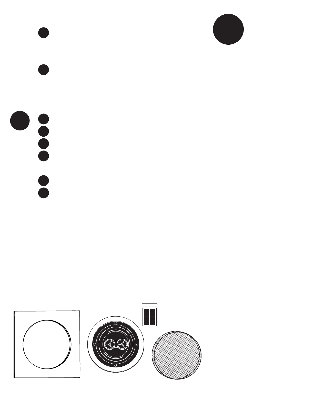
DRAWING 1
Cut-Out Template
Speaker
Grille
TABLE OF CONTENTS
A
WHAT YOU NEED
TO DO THE JOB
SPEAKER SYSTEM
PARTS INVENTORY
Before you get involved in the actual installation
process, it’s a good idea to check for possible
shipping damage and identify parts and hardware.
You should have the parts shown in Drawing 1:
mOne (1) B.I.CMuro loudspeaker system
with attached grille
mWhite cardboard mounting template
mWhite cardboard masking template for
painting
mBlack grille adhesive
If anything is missing after a thorough search
of the box and packing materials, contact the
dealer where you bought your speaker.
Although the B.I.CMuro Ceiling System is
extremely well packed to withstand the rigors
of shipping, you should still inspect it closely,
especially if there is any damage to the outside
carton. If you find anything wrong, contact your
dealer or the shipper who delivered the speaker.
TOOLS FOR INSTALLATION
IN EXISTING WALLS
It doesn’ttake a whole workshop to install
your new speaker, just a few simple tools:
mApencil
mAdrill with a 1-inch flat bit
mAretractable utility knife or keyhole saw
mAlength of stiff wire about 3 feet long (a
straightened wire coat hanger works fine)
mAPhillips-head screw driver which will fit the
black screws included with your speakers
mApair of diagonal pliers or wire strippers
Some of the following may also be needed,
depending on the application.
mAstud finder
mDrill bit just slightly larger than the diameter
of one speaker wire
mPlumb bob or small weight on a string
mInsulated staples for securing speaker wire
mMasking tape or foam “double-stick” tape
mPaint and applicator for changing grille and
outer frame finish
Black grille
adhesive in
polybag

3
SPEAKER WIRE
The amount of wire you’re going to need will of
course vary with speaker placement (which we
cover next). But we’re covering the subject of
wire now because it’s something you may have
to go out and obtain along with whatever tools
you don’t already have.
What kind to use
Werecommend using inexpensive, multi-stranded
“zip-cord” for amplifier-to-speaker connections.
Also called lamp cord, it’s sold in pre-packed
rolls and in bulk displays at hardware, lighting
and home improvement stores. Zip-cord’s out-
side covering (insulation) can be transparent,
black, brown, white, etc. Color doesn’t matter.
Thickness does. For in-wall and in-ceiling, a good
quality wire should be used so the outside plastic
covering won’t crack and break down over time.
Selecting the proper gauge
Wire is measured in “gauges.” For no particularly
good reason, the bigger the number, the smaller
the wire. For example, 18-gauge is thinner than
14-gauge.
The gauge of wire you need is determined by the
distance between your amplifier/receiver and
the speakers. Use the following chart as a guide:
Length Minimum Gauge
Less than 10 ft. 18
10 to 50 ft. 16
Over 50 ft. 14
If in doubt, be safe and get a smaller gauge
(i.e. thicker wire). Using too thin a gauge over
along distance can compromise sound quality.
And besides, there isn’t a vast cost difference
between gauges, anyway.
How much to buy
Basically,more than you think you need. As we
noted earlier, a discussion of lengths is sort of
premature until you’ve decided on exact place-
ment, so you may want to skip to Section B on
“Where to put your speakers.” But if you
have a rough idea of the distance from your
amplifier to the speakers, here are a few tips:
•Because of the complicated paths which are
often required to route wires, you’ll definitely
need more than the amount derived from
simple measurements.
• Professional installers often use the following
rule of thumb: “As the crow flies” amp to
speaker distance TIMES FIVE. That allows
enough for both speaker paths plus a very
healthy margin for unplanned detours.
Remember the electrician’s favorite adage:
“You can always cut off extra wire, but
they don’t stretch worth a darn.”
use a more powerful amplifier if you take some
simple precautions, which we cover on page 7
(“Taking care of your new Muro speakers”).
Amore serious consideration is whether or
not you intend to power more than one set of
speakers with the same amplifier or receiver. If
you intend to hook speakers to both “A” and
“B” receiver outputs and then play both sets of
speakers at the same time, you should read the
section starting on page 7 of this manual
(“More on amplifiers and impedances”),
to avoid potential problems.
B
VARIOUS USES
B.I.CMuro Stereo Ceiling Speakers can be
used for background music, as a primary
listening system or as built-in rear surround
speakers in an audio/video home theater.
Background music
If you just want low-volume background
music to float through a room, placement for
best acoustics is not particularly critical. You
can pretty well ignore all our diagrams and tips
on imaging and other acoustical matters. Just
put your speaker where it’s convenient and non-
intrusive to room decor. You can even place the
speaker in an adjoining room, such as a living
room that flows into a formal dining room, or in
akitchen and breakfast nook.
Surround sound
B.I.CMuro Stereo Ceiling Speakers make excellent
surround sound speakers. They can be mounted
at ear level in any of the positions shown in
Drawings 2 and 3 especially from the ceiling.
OTHER ACOUSTIC
CONSIDERATIONS
For best fidelity, there are several other factors
to keep in mind before you start actual installation.
Muro ceiling speakers may be used
for rear surround sound channels
by placing them (1) behind or (2) in
the ceiling, just behind the viewer.
DRAWING 2
DRAWING 3
Open
Attic
Muro
Speaker
Standard Room
1
2
DRAWING 4
Cone of
Coverage
AMPLIFIER CONSIDERATIONS
Virtually any receiver,power amplifier or
integrated amplifier can be used with your B.I.C
Muro Stereo Ceiling Speaker. Although Muro
speakers are rated for high power,it’s OK to
WHERE TO PUT
YOUR SPEAKERS
Since these are primarily used in ceiling applica-
tions, we highly recommend installing in an open
attic space. If you need to go into the ceiling of a
first floor room (in a two story house), we rec-
ommend the use of a professional installer.
Placement can make all the difference in how
your B.I.CMuro speaker systems sound – and
how easy they are to install. There are at least
Vertical placement
Treble frequencies are
quite directional. While
the dome tweeters in
B.I.C Muro MSR5D,
MSR6D, and MSR8D
speakers are designed
to disperse high fre-
quencies over a wide
area, they will give you
the best sound when
positioned so that they
three “WHERE’S” and a “HOW” to factor into
your layout:
• HOW you intend to use your speakers
• WHERE they’ll sound best (acoustic
considerations)
• WHERE it’s possible to install them
(ceiling surfaces)
• WHERE they can be installed that makes it
easy to get wire to them without remodeling
your entire house.
cover the listening area in a cone of coverage as
shown in Drawing 4. Of course, if the speakers
are being installed in an area where listeners usu-
ally stand up (such as a kitchen or hallway), they
are best suited for ceiling mount (see Drawing 3).
Corners and reflections
When a speaker is placed close to the corner
of a room, bass frequencies are emphasized.
Treble is emphasized when it reflects back from
reflective surfaces such as large windows. Con-
versely,highs tend to be muffled by soft surfaces
such as drapes, rugs, upholstered furniture, car-
peted steps and even textured fabric wall paper.
4
WALL AND CEILING SUR-
FACES
Now that we’ve covered where you should
put your speakers, let’s consider where you
CAN put them.
B.I.CMuro MSR5D’s require at least 23/4˝of
depth, MSR6D’s require at least 31/16˝, and
MSR8D’s require at least 37/16˝(measured from
the outside surface of the wall).
This means that they can be installed in any
wallboard-and-2 x 4 stud wall. In fact, the dense,
rigid nature of plasterboard or (lath and plaster
in older homes) acts as a superb speaker baffle.
You can also install B.I.CMuro speakers in
stud walls covered with thick wood paneling or
in wallboard/plaster ceilings.
However, avoid:
• Stud walls covered only with thin veneer
paneling – the surface isn’t rigid enough and
can cause annoying vibrations and buzzing.
• T-bar “drop ceilings” with very thin
fiberboard panels which can buzz and
vibrate. If you suspect this will happen,
reinforce the drop-in panel with wood or
particle board.
• Any wall which can’t provide proper depth
(clearance) for the back of the Muro
speakers to protrude. This includes brick
or concrete walls where the wallboard or
paneling is attached to thin furring strips.
• Walls where you know that there are pipes,
heating ducts and ESPECIALLYAC wiring in
the general vicinity.For example, if there is
an outlet along the baseboard, there is often
alive wire running partly up the wall at
that point.
SPEAKER WIRE PATHS
The last consideration is the obstacle course
that lies between the speakers’ hoped-for
mounting positions and your stereo system.
Wire can be run through crawl spaces that lie
above your ceiling or below the floor, through
basements of second stories, or simply along
the perimeter of your listening room. We cover
each of these options in detail in the “Running
connecting wires” section of this manual.
In general, you should pay particular attention
to the following areas:
• Avoid running speaker wires close to house
electrical wiring for any distance. If you have
to run them parallel, make sure to space the
speaker wires at least two feet from the AC
line. It is, however, OK for speaker wires to
cross paths with AC line or go through the
same hole together with house wiring if they
separate before and after.
• Make sure that the entire path between
speakers and amplifier is clear and not
obstructed by a major floor or ceiling joist
or masonry wall which you won’t be able
to drill through.
PAINTING YOUR
SPEAKERS
If you like the designer white finish which
has been applied to your B.I.C Muro Speakers,
you can skip to Step D, next page. But if you
want your speakers to completely blend in
with a colored wall or accent the surface,
now is the time to paint your Muro speakers’
outer frames and perforated grilles.
The speaker’s outer surfaces are primed to
accept ordinary latex wall paint or aerosol spray
paint. Because the surface behind the perforat-
ed grille should remain black, you will need to
mask this area off before you begin painting.
1. First the speakers’ grille must be removed.
From the back of the speaker, use the
mounting legs to push the grille off.
2. Paint the outer speaker frame and grille
separately. A roller with a short or medium
nap will work much better than a brush. If
you’re using spray paint, make sure that
you achieve the same coverage on both
grille and frame. You must take extreme
precautions when painting the grille not to
get paint in the holes of the grille.
There’sno need to replace the grille at this
time since you will need access to the inner
speaker surface during installation.
C
•Remember that the other end of the wires
has to come out somewhere to connect
with the amplifier. Confirm ahead of time
that you can drill an outlet hole easily and
in an unobtrusive spot. D
CUTTING HOLES
FOR THE SPEAKERS
Wallboard is an easy surface in which
to make a relatively neat hole. Actually, the
hole doesn’t even have to be that neat, since
the speaker’s outer frame will cover it. Just
make sure you don’t make it any bigger than
the template. In the following steps, you’re
going to locate a section of ceiling between
the woodframing or in the wall between two
studs, mark the outer boundaries of the hole,
drill a small hole in the center to confirm
your location and then cut the main hole.
DRAWING 5
A. Trace template
outline
B. Drill 1 inch
pilot hole
C. Probe with
wire for stud
clearance
D. Cut speaker
hole along outline
1. First you must determine the location of your
ceiling supports or wall studs so that the
speaker can be approximately centered
between them. There are several ways to go
about this:
• Tap on the surface and listen to the result-
ing “THUMP”. When it’sdeeper, you’re
between studs. When it’s sharper and more
flat-sounding, you’re close to a stud.
•Use a stud-finder, a simple little magnetic
device which works by locating the lines of
nails hammered into the stud.
•Identify wall studs by the position of elec-
trical outlets or switches. There’ll be a stud
either directly to the left or right of an elec-
trical fixture. This gives you a point of mea-
surement, since studs are either 18 or 16
inches apart in newer houses, 12 inches
apart on pre-WW2 homes.

2. When you’re reasonably sure of where the
ceiling joist (studs or framing) or wall stud
2 x 4’s are (and are TOTALLY sure that there
isn’t an electrical cable, water pipe or heating
duct in that vicinity of your proposed cutout)
position one of the cardboard mounting tem-
plates and draw around the inside outline with
apencil.
3. Drill a 1-inch hole in the center of the pencil
outline which you have just drawn.
4. Obtain a length of stiff wire such as an un-
wound, totally un-bent coat hanger. Bend it
so that the last 12 inches is at a right angle to
the rest.
5. Insert the angled part into the 1-inch hole you
just drilled and probe to left and right to con
firm that a stud is not close on either side.
•If there is a close stud on one side, just re-
position the cardboard template a few inches
in the opposite direction and re-draw y o u r
pencil outline, keeping the 1-inch hole within
the pencil outline’sinner boundaries.
6. If there are no obstructions, cut the hole along
the pencil outline. If the surface is wallboard,
simply cut it increasingly deeper with utility
knife until it gives way and then pull it out by
grasping the cut-out through the 1-inch hole.
•If you’re dealing with lath and plaster or
thick paneling, you need to use a different
technique. Drill 1-inch holes at the corners of
the pencil outline. Then use a keyhole saw or
even a hacksaw blade with VERYslow strokes
to saw through and remove the inner surface.
7. Temporarily place the B.I.CMuro speaker
into the cut-out to insure that it fits properly.
It’s OK if the hole is slightly large, since it will
be covered by the speaker’soutside frame.
Actual installation will happen later,after
you’ve routed the speaker wires.
8. Now it’s time to drill the hole on the OTHER
end – at the point where the wires from the
speakers will exit to the amplifier/receiver.
•Use the same 1-inch drill bit as before.
• If you want a totally finished job, install an
outlet box against a stud and cover it with a
TV cable or single outlet plate which has one
hole in the middle for the wires to exit from.
5
E
RUNNING
CONNECTING WIRES
Now you know were the wires have to run.
It’s time to actually route them.
1. UP TO SPEAKER you have an attic or
overhead crawl space, your two steps are:
1) Up from the amplifier to the crawl space;
2) Across the crawl space to the speaker.
UP TO SPEAKER
(ATTIC CRAWL SPACE)
See drawing 6
1. You’re about to ascend into your attic.
Grab the following:
•Tape measure
• Cordless drill with a 1-INCH BIT (or non-
cordless model with long extension cord)
•A VERY long roll of speaker wire
•Wire cutters – either diagonal pliers or
wire strippers which include a cutting surface.
•Plumb bob or string with a small weight
(such as a metal nut) on the end
• Tape – any kind will do
2. Crawl up into the attic with all the afore-
mentioned stuff and proceed to a spot that’s
directly over the speaker cut-out hole.
3. Time to use that roll of cable. Push two
cables through the speaker cut-out.
4. Making sure the ends don’tget pulled back
up through the hole, reel out cable while
moving across the attic/crawl space until you
reach the location above your amplifier.
5. Extend at least 10 (TEN) more feet of cable
for the roll and cut it.
6. You now have cables running from the
speaker. Time to get them down the wall
to where the amplifier will be.
7. Drill a 1-inch hole through the horizontal
2 x 4 directly above the amplifier wall outlet.
8. Now you’re going to guide cables down to
where they’ll emerge from the wall. Since this
hole isn’t very big, just stuffing them down and
grabbing them won’t work. Instead, it’s time
for the plumb bob or string-with-weight (or
wire if there’s insulation to contend with).
Tape the two cable ends (which come from
the speaker) to the plumb bob string just
above the weight and lower the whole thing
down through the 1-inch hole above the
amplifier. You’ll probably have to “feed out”
the attached cable to get the weight to descend.
9. Continue “feeding out” both cables until they
and the weight hit bottom. Tie the free end of
the plumb bob string to something so that it
doesn’t fall down the hole.
10. Exit the attic crawl space and stretch for a bit.
11. Go over to the 1-inch amplifier wire hole
and look for the extended string/plumb bob
and attached cables. If they’re not visible, fish
around for them with your stiff wire/unbent
coat hanger and pull them through the hole.
Then rescue the plumb bob from the attic.
12. At the speaker hole, things are much easier.
You can just reach through and grab the
cables. Pull their whole free length out the
cut speaker hole. You’ve done it!
DRAWING 6 DRAWING 7
F
HOOKING UP
YOUR SPEAKER
The main thing to remember when hooking up
the speaker is that two conductors in the speaker
wire are not interchangeable. One will be used as
a POSITIVE (+) conductor and the other as a
NEGATIVE (-) conductor. These correspond to
the RED (+) and BLACK (-) connectors on your
B.I.C Muro Ceiling Speaker and also to the
speaker terminals on your amplifier or receiver.
IDENTIFYING “+” and “-”
Your need to be able to discriminate between
the two conductors in the zip cord.
If your wire has transparent insulation, this is
easy: One conductor will be copper-colored and
the other silver-colored. Generally, professionals
denote the copper one as POSITIVE (+) and
the silver one as NEGATIVE (-).
If you’ve used wire which has an opaque insu-
lation, there are still differentiating markings.
Examine the wire closely and look for:
• A series of ribs or grooves on one conductor
• A painted stripe
• A single strand of yarn intertwined with the
multi-stranded wire in one conductor.
Denote any of these as the POSITIVE (+) con-
ductor for similar connections on both ends.
AT THE SPEAKER END
1. Cut off excess wire, leaving about 2 feet
extending through the speaker cut-out hole
for the left and right channel.
2. Pull the conductors apart so they’re separated
for the first two inches from their ends.
3. Using wire strippers, diagonal pliers or a
knife, remove 1/2inch of insulation from
each conductor.
4. Twist the tiny strands in each conductor into
tight spirals, as shown in Drawing 7.
5. IMPORTANT: Route the speaker wires
THROUGH the hole in the ceiling (Drawing 8).
6. Attach the left speaker wires to one set of red
and black speaker terminals. Press down
on the protruding levers while inserting the
wire into the hole.
•Connect the POSITIVE (+) conductor to
the RED terminal and the NEGATIVE (-)
conductor to the BLACK speaker terminal.
•Make sure that no stray strands of wire
have gotten detached and are touching the
other main wire.
Repeat the connection for the right channel
wire to the other set of input terminals (Note:
It does not matter which is right and which
is left).
AT THE AMPLIFIER END
1. Cut off excess wire, leaving enough to com-
fortably reach from the hole in the wall to
your stereo system. If there’s a possibility that
you’re going to move the amplifier to ano-
ther part of the room, consider leaving some
excess wire coiled up. If you’ve used suffi-
ciently thick wire, this extra length will
not affect speaker performance and
could make things easier if the room is
rearranged later.
2. Pull the conductors on both speaker wires
apart so they’re separated for the first two
inches.
3. Using wire strippers, diagonal pliers or a
knife, remove 1/2inch of insulation from
each conductor.
4. Twist the tiny strands in each conductor
into tight spirals.
5. Attach the speaker wires to the red and black
speaker terminals on the amplifier or receiver.
•Connect the POSITIVE (+) conductor to
the RED terminal and the NEGATIVE (-)
conductor to the BLACK speaker terminal.
•Make sure that no stray strands of wire
have gotten detached and are touching the
other main wire.
DRAWING 8
6
DRAWING 9
FINAL ASSEMBLY
1. If you haven’t done so already during paint-
ing, remove the perforated grilles from
your Muro Ceiling Speaker. To remove
the grille, just use the mounting screw (dog
leg) on the rear to push the grille off.
2. See Drawing 9. Make sure all the clamping
brackets (dog legs) are turned inward as
shown in the picture before going up on the
ladder to install the unit in the ceiling.
3. Find the wires you ran previously (hopefully
hanging down through the hole you cut).
Strip the ends if you haven’t already done so
and connect as described in Section F.
4. Insert the speaker into the cutout hole and
be certain the wires are not hanging down
on the woofer cone.
5. Using a Phillips screwdriver (or powered
screwdriver,recommended), start tightening
the four screws. As you start the tightening
each of the mounting brackets (dog legs) will
swing around and follow the screw down to
the back of the wall and clamp the speaker
into place. Avoid excessive force when
tightening the screws to prevent deforming
the drywall or breaking the plastic clamp of
the speaker. Be sure to go around all four
screws and check for even tightness in the
clamping pressure.
6. Replace the grille by gently pressing it into
place. Use the supplied black grille adhesive
around the edge of the grille when pressing
it into place.
7. Repeat the above steps for the other speaker.
At this point you are finished with the installation.
G
ASHORT TEST DRIVE
It’s a good idea to test everything out at this
point. Also, although we’ve paid close attention
to speaker polarity, we haven’t concerned our-
selves with which wires went to left and right
inputs. If you have connected your new Muro
Ceiling Speaker to the rear “surround” output of
your receiver,you will need to put your receiver
in the “Pro-Logic” or “Digital” mode and use a
source such as a DVD player or Hi-Fi VCR and
suitably recorded movie to test your receiver sur-
round operation.
1. Turn on your stereo system. Make sure that
the VOLUME control is turned down and that
the BALANCE control is set to center.
2. Activate a musical source such as FM, a tape
or CD player.
3. Gently turn up the volume. You should hear
music coming out of your new B.I.C Muro
Ceiling Speaker! (If you don’t, refer to the
troubleshooting guide below.
4. Now rotate the stereo’sBALANCE control all
the way to the LEFT. Sound should come out
of your speaker.
5. Rotate the BALANCE control all the way to
the RIGHT. Sound should come out of the
speaker.
6. If this is the case, your installation is a success.
We suggest you read the section on the next
page titled “Taking care of your new
Muro Speakers” (for further operating tips).
H
Left channel
wire
Right channel
wire
Left or
right wire
ONE INPUT
SHOWN
Hook other
channel to
other input
connector on
speaker.

7
A QUICK
TROUBLESHOOTING GUIDE
Before returning your B.I.CMuro Ceiling
Speaker for service, it’s a good idea to check
out these simple remedies first.
No sound from the speaker
1. Incorrect source selected on receiver or
preamplifier.
2. Mute button pressed on receiver.
3. Wrong speaker output selected – many
receivers have an “A” and “B” speaker
switch. Make sure it’s in the right position.
4. Un-secure connection at either the speaker
or amplifier – double check them.
5. Balance control turned all the way left or
right – return it to center.
6. Bad connecting cable between sound
source and amplifier – try a new cable.
7. Defective speaker – contact your B.I.C
dealer or call 1-877-558-4242.
Intermittent sound from speaker or
speaker plays initially but then shuts off.
1. Short circuit at either the amplifier or
speaker connectors is activating the amp’s
protection circuits – double check connec
tions, making sure no stray strands of wire
from one conductor are touching the other.
Speakers plays but sound is mixed
with hum
1. It could be a faulty patch cord. If so, there
will be hum from your main speaker system
as well as from your Muro Ceiling Speakers.
Assuming you didn’thave hum in your system
before, one or both of the speaker wires has
been run too close to internal AC house
wiring. Re-route it so that it stays at least
2feet away from AC power wiring when
running parallel.
Speaker plays but sound is muffled and
“strained.” Amplifier may shut off if
volume is raised too far.
1. Too thin a gauge of wire has been run too far
adistance between amp and speaker. Make
sure that you have followed our suggestions
as to wire gauge versus overall distance.
When volume is turned up to a high
level, the treble cuts in and out.
1. The Muro Stereo Ceiling Speaker features a
special protection circuit which electronically
disconnects the tweeter if it starts getting too
hot. Turn down your amplifier and make
sure to read the section of this manual
titled “Taking care of your new Muro
speakers” which starts on this page.
FURTHER READING
TAKING CARE OF YOUR
NEW MURO SPEAKERS
B.I.CMuro Ceiling Speakers are designed
to last the life of your home – if you follow a
few simple rules.
The main “killers” of any loudspeaker system
are 1) too little power at high volumes, 2) too
much power at high volume, 3) transient thumps.
Not enough power
It’s a surprising fact, but far more speakers are
damaged by too little power than by too much!
When an amplifier runs out of power while try-
ing to re-create musical peaks, it causes a form
of high frequency distortion called clipping. In
moderate amounts, clipping simply makes the
music sound terrible. In greater quantities over
a period of time, it can damage or destroy the
tweeters (high frequency reproduction speakers)
in any speaker system. If you like your music
LOUD, consider getting an amplifier with at least
60 watts per channel.
Too much power
There’s nothing wrong with driving your
B.I.CMuro Speakers with a high power amp –
the extra power helps them achieve quick
musical transients found in digital recordings.
However, you must remember to restrain your-
self and not get too heavy-handed with the
volume control (or remote buttons). If the
music begins to sound distorted or you hear a
“clacking” sound during bass notes, back off!
And naturally, if the internal protection circuits
are intermittently shutting off the tweeter,
you’re exceeding its safe power input level.
Transients
Loud, deep THUMPs, caused when you turn
your stereo on or off, can seriously damage any
loudspeaker including your B.I.C Muro ceiling
models. It’s always a good practice to turn the
volume down (or press the MUTE button if your
receiver has one) when changing sources (such
as changing from tuner to CD player input). Also
remember to turn your system off before discon-
necting any hook-up cables. When they’re pulled
out, a huge burst of low frequency hum often
occurs if the system is still on.
Cleaning
B.I.CMuro Ceiling Speakers are covered with
adurable finish which can be cleaned with
soap and water or spray cleaners. Avoid the use
of ammonia-based cleaning products, however.
If you’ve painted the grilles and frames, follow
the paint manufacturer’s cleaning instructions.
MORE ON AMPLIFIERS
AND IMPEDANCE
Not all amplifiers or receivers can safely
operate two sets of speakers at once. If you
intend to use your B.I.C Muro Ceiling Speakers
at the same time as your main speakers –
or if you intend to hook up two sets of Muro
Ceiling Speakers and use both at the same time,
it’s important to consider both the impedance
of the speakers and the capabilities of the
amplifier you’re using.
First consult the owner’s manual that came
with the amp or receiver. It should tell you the
minimum speaker impedances during simulta-
neous operation. On some models, the manual
will recommend that only two pairs of 8 ohm
speakers be used at the same time. Others
might allow one set of 8-ohm speakers and
one set of 4-ohm impedance speakers. A few
extremely robust receivers and power amplifiers
may even allow two sets of 4-ohm speakers.
If you can’t readily determine this information,
consult the dealer where you purchased the
amplifier, or call the manufacturer.
Next, determine the impedance of your other
speakers. It’s often printed on the back of the
enclosure down near the connection terminals,
or you can consult the speaker’s owners’ manual.
Both B.I.CMuro Stereo Ceiling Speakers are
rated at 8 ohms impedance per channel. In gen-
eral, this means that most amplifiers will allow
you to simultaneously operate one Muro Stereo
Ceiling Speaker and one other set of 8-ohm
loudspeakers – or two sets of Muro Stereo
Ceiling Speakers.
If your other speakers are rated at 4 ohms,
some amplifiers may experience difficulty dri-
ving both sets at once and shut off intermit-
tently when the volume control is turned up.
In this case, you should operate only one
set of speakers at a time or keep the volume
extremely low.
INSTALLING B.I.CMURO
SPEAKERS DURING NEW
CONSTRUCTION
Needless to say, installing speakers when a
house is being built is far easier than doing
it later.
• If possible run speaker wires after AC
wiring is in place to avoid induced hum
caused by close parallel proximity.
• Secure speaker wires in place along the run
with insulated staples only and be careful
not to pierce the insulation. Allow a bit of
slack for expansion of building materials.
• Needless to say, the actual speakers should
not be installed until the wall board is in
place. In the meantime, leave several feet
of wire coiled up and secured to the back
side of the speaker opening.
• When it comes time to put up the drywall,
make sure the speaker cut out hole doesn’t
extend farther than the sides of the mount-
ing frame.
• After the wallboard is put up, install the
speakers as detailed on page 5 of this manual.

8
B.I.CMuro Speakers
Three-Year Limited Warranty
If the Muro speaker system proves to be
defective in materials or workmanship within
three years from the date of the original cus-
tomer’spurchase, we will at our option, repair
or replace the defective product.
Limitation of Implied Warranties
Any implied warranties, including warranties
of merchantability and fitness for a particular
purpose, are limited in duration to the length
of this warranty.
Disclaimer
THE WARRANTY STATED HEREIN IS IN LIEU
OF ALL OTHER WARRANTIES, EXPRESSED OR
IMPLIED, INCLUDING MERCHANTABILITY AND
FITNESS FOR PARTICULAR PURPOSE AND ALL
OTHER LIABILITIES AND OBLIGATIONS OF
B.I.C AMERICA, ALL OF WHICH ARE EXPRESSLY
DISCLAIMED, B.I.C AMERICA HAS NOT MADE
AND DOES NOT HEREBY MAKE ANY OTHER
REPRESENTATION, WARRANTY OR COVENANT
WITH RESPECT TO THE CONDITION, QUALITY,
DURABILITY, DESIGN, OPERATION, CAPACITY,
FITNESS FOR USE OR SUITABILITY OF THE B.I.C
ELECTRONIC PRODUCT.
Exclusion of Certain Damages
Muro Systems’ liability for any defective
product is limited to repair or replacement of
the product at our option. Muro Systems shall
not be liable for incidental or consequential
damages of any kind or character because of
product defects.
Some states do not allow limitation of how
long an implied warranty lasts and/or do not
allow the exclusion or limitation of incidental
or consequential damages, so the above limita-
tion and exclusions may not apply.
This Warranty Does Not Cover
Damage caused by abuse, accident, misuse,
negligence, or improper operation (installation).
Products that have been altered or modified.
Any product whose serial number has been
altered, defaced or removed.
Normal wear and maintenance.
Damages caused by shipping (All claims for
shipping damages must be made with the carrier.)
Warranty Service
Warranty service must be performed by an
authorized service center, usually a Muro
speaker system dealer or its authorized agent.
You may obtain a list of authorized service cen-
ters by calling the number below.
All warranty repairs must be accompanied by
the original bill of sale. No other document is
acceptable or required.
Many advertise through small community papers
or even via signs on bulletin boards.
2. Phone installation services.
Larger companies which specialize in installation
may be found in the Yellow Pages under the
following listings: Telephone Equipment &
Systems – Wiring & Installation or
Telephone & Television Cable Contractors.
These firms charge more than freelance installers
but are also easier to locate and contact.
3. Custom stereo installation contractors.
Although they prefer to specialize in complete
“turnkey” installs, many stereo installation
companies are also willing to do hourly work.
Unfortunately, they’re buried in the listings with
regular stereo dealers (under Stereophonic &
High Fidelity Equip - Dirs), so you may have
to make several phone calls to find one.
4. Electrical contractors. As a last and
expensive resort, you can always use a true
electrical contractor. They’re listed in the
Yellow Pages under Electric Contractors.
Muro is a registered trademark of B.I.CAmerica. Dolby is
aregistered trademark of Dolby Licensing Corporation.
Specifications
MSR5D MSR6D MSR8D
Frequency response . . . . . . . . . . 58Hz - 21,000 Hz Frequency response . . . . . . . . . . . .53Hz - 21,000Hz Frequency response . . . . . . . . . . . . . 40Hz - 21,000Hz
Recommended amplifier power. . . . . . . . . 75 watts Recommended amplifier power . . . . . . . . . .85 watts Recommended amplifier power . . . . . . . . . . 100 watts
Sensitivity ............................90dB Sensitivity . . . . . . . . . . . . . . . . . . . . . . . . . . . . .90dB Sensitivity . . . . . . . . . . . . . . . . . . . . . . . . . . . . . . 90dB
Woofer . . . . . . . . . . . . . . . . . . . . . . . Dual coil 51/4˝ Woofer . . . . . . . . . . . . . . . . . . . . . . . .Dual coil 61/2˝ Woofer . . . . . . . . . . . . . . . . . . . . . . . . . . . Dual coil 8˝
Tweeter . . . . . . . . . . . . . . . . . . . . . . . . . . . . Two 1/2˝ Tweeter . . . . . . . . . . . . . . . . . . . . . . . . . . . . .Two 1/2˝ Tweeter . . . . . . . . . . . . . . . . . . . . . . . . . . . . . . Two 1/2˝
Crossover type ....................First Order Crossover type .....................First Order Crossover type . . . . . . . . . . . . . . . . . . . . . . First Order
Impedance.....................8ohms/input Impedance . . . . . . . . . . . . . . . . . . . . . .8 ohms/input Impedance . . . . . . . . . . . . . . . . . . . . . . . 8 ohms/input
Dimensions..........................8˝dia. Dimensions . . . . . . . . . . . . . . . . . . . . . . . . . . .9˝ dia. Overall Dimensions . . . . . . . . . . . . . . . . . . . 103/4˝dia.
Required cut-out . . . . . . . . . . . . . . . . . . . . 61/2˝dia. Required cut-out . . . . . . . . . . . . . . . . . . . . .71/2˝dia. Required cut-out . . . . . . . . . . . . . . . . . . . . . . 91/2˝dia.
Required depth . . . . . . . . . . . . . . . . . . . . . . . . 23/4˝ Required depth . . . . . . . . . . . . . . . . . . . . . . . . .31/16˝ Required depth . . . . . . . . . . . . . . . . . . . . . . . . . . 37/16˝
Due to our continual efforts to improve product quality as new technology and techniques become available, B.I.C America reserves the right to revise speaker systems specifications without notice.
B.I.CMSR5D, MSR6D, AND
MSR8D DESCRIPTIONS
AND SPECIFICATIONS
The MSR5D, MSR6D, and MSR8D are stereo
2-way speaker systems which have been ruggedly
constructed to withstand not only the extreme
dynamic range found in today’s digital sound
sources, but also the rigors of temperature vari-
ation, dust and moisture encountered in perma-
nent installation. Above all, they have been
designed to give you the finest possible music
reproduction possible in modest-sized speakers.
The MSR5D features a 51/4˝dual-coil long-
throw, polypropylene woofer and two 1/2˝
neodymium, mylar, ferrofluid-cooled dome
tweeters. A mylar capacitor is used in a First
Order crossover configuration to prevent low
frequencies from entering the tweeter as well as
self-resetting tweeter protection.
The M-SR6 employs a 61/2˝dual-coil long-throw,
polypropylene woofer with high-compliance foam
surround to achieve additional bass response. Two
1/2˝neodymium, ferrofluid-cooled mylar dome
tweeters achieve excellent transient response
and wide dispersion of high frequencies. A first
order tweeter crossover is used for superior
performance and long tweeter life. It also incor-
porates a self resetting tweeter protector.
The MSR8D features an 8˝ dual-coil long-throw,
polypropylene woofer with high-compliance
rubber surround to achieve additional bass
response. Two 1/2˝neodymium, ferrofluid-cooled
mylar dome tweeters achieve excellent transient
response and wide dispersion of high frequen-
cies. A first order tweeter crossover is used for
superior performance and long tweeter life. It
also incorporates a self resetting tweeter protector.
OUTSIDE HELP
If you don’t feel that you’re up to undertaking
installation – or if you start it and for some
reason can’t finish you have several alternatives
for outside help.
1. Freelance telephone installers.
With the deregulation of the phone company, a
whole new industry has sprung up. These people
are experts at stringing wires unobtrusively and
have the tools to do the job quickly and easily.
TM
B.I.CAmerica
925 N. Shepard Street
Anaheim, CA 92806
www.bicamerica.com
Tech Support: 1-877-558-4242 (4BIC)
This manual suits for next models
2
Table of contents
Other B-I-C America Speakers manuals

B-I-C America
B-I-C America Acoustech AuraPro Series Installation instructions

B-I-C America
B-I-C America muro ARCHITECTURAL M-PRO6W Installation instructions

B-I-C America
B-I-C America FORMULA FH6-C Installation instructions

B-I-C America
B-I-C America Venturi VK-6IO User manual

B-I-C America
B-I-C America FH8-W Installation instructions

B-I-C America
B-I-C America DV62si User manual

B-I-C America
B-I-C America DV32CLR User manual


