B.M.C. DAC 1 User manual

DAC 1
Owner's Manual
1102‐EN
B.M.C. Audio DAC 1
Quick Start
Find a detailed description and illustration inside this owner's manual.
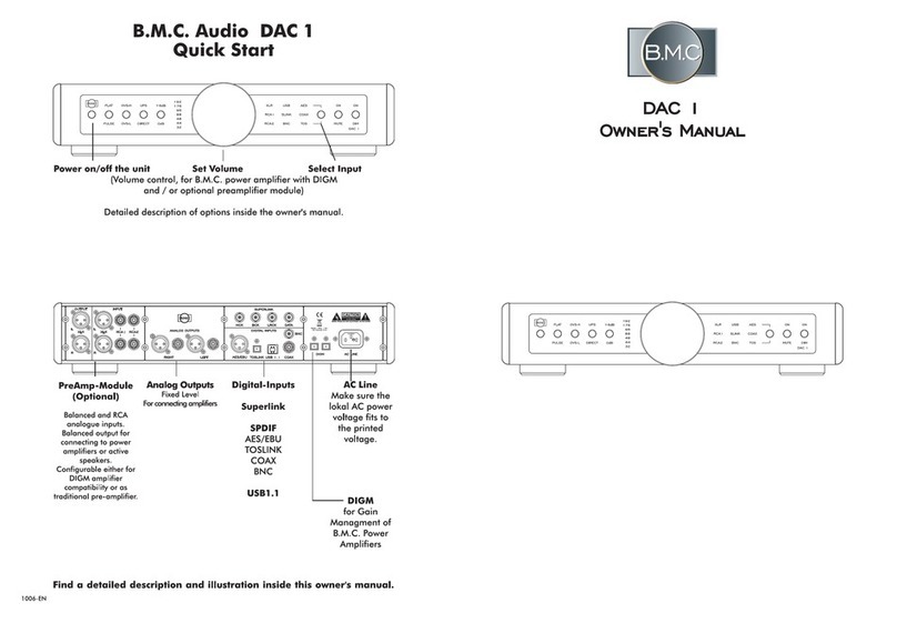
Power on/off the unit Set Volume Select Input
(Volume control,for B.M.C.power amplifier with DIGM
and /or optional preamplifier module)
Detailed description of options inside the owner's manual.
PreAmp‐Module
(Optional)
Balanced and RCA analogue
inputs.
Balanced output for connecting
to power amplifiers or active
speakers.
Configurable either for DIGM
amplifier compatibility or as
traditional pre‐amplifier.
Analog Outputs
Fixed Level
For connecting amplifiers
Digital‐Inputs
Superlink
SPDIF
AES/EBU
TOSLINK
COAX
BNC
USB1.1
AC Line
Make sure the lokal
AC power voltage
fits to the printed
voltage.
DIGM
for Gain
Managment of
B.M.C.Power
Amplifiers

215
Table of Content
Introduction,Content of Packing
Front Panel Functions
Rear Panel Description
Digital‐Filter‐Options
Volume Control,Variable Output
Interconnection Options ‐SUPERLINK,SPDIF,USB
Remote Contol Handset
Troubleshooting,Maintainance,Service
Important Safety Information
General Safety Precautions
CE /FCC‐Declaration,Recycling
Attachment:Jumper Settings
Technical Specifications DAC1
Quick Start
B.M.C.AUDIO GmbH,Van‐der‐Reis‐Weg 9, 59590 Geseke,Germany
WWW.BMC‐AUDIO.COM INFO@BMC‐AUDIO.COM
Technical Specifications DAC1
3
4
5
6
7
8
9
10
11
12
13
14
15
16

14 3
Introduction
Thank you for purchasing B.M.C.'s DAC1and congratulations for choosing this exceptional component!
We also like to thank you for supporting the puristic SUPERLINK interconnection system by this
purchase.
It makes more sense and thus it is easier to reduce jitter when having the "Master‐Clock"inside the
Digital to Analogue converter,just the way SUPERLINK is doing.The separate transmission of the
"Master Clock", "Bit Clock", "Left‐Right Clock"as well as the audio data also avoids degredations by
coding and later decoding such signals into a single stream,like SPDIF transmission is doing.As long
as your CD‐transport supports SUPERLINK this is the best interconnection to a DAC.
Additionally to the SUPERLINK concept sophisticated clock‐synchronisations for the digital audio signal
keep the signal quality on the highest level.
One key for the exceptional sound quality is the global‐feedback‐free analogue section.With its CI‐
input (CI =Current Injection)input the DAC‐chip get the optimum interface and the extremely fast
circuit is insensitive to digital noise,preserving all musical information.The LEF output driver delivers a
stable output signal,again without a sound degrading global feedback loop.LEF (Load Effect Free)is
a balanced,cascoded,single‐ended‐class‐A circuit with a separate delivery of signal voltage and
signal current.
With DAC1's DIGM‐controller feature it is possible to achieve a high‐end audio system with very short
signal path,by connecting a B.M.C.power amplifier via the fixed level outputs and adjusting the volume
by losslessly changing the power amplifier's gain through DAC1's volume knob.For high end audio
systems with digital sources exclusively the DAC1handles all preamplifier functions.
Optionally an additional preamplifier module is available,featureing 2RCA and one balanced XLR
analogue inputs in addition to the digital inputs.A balanced XLR output interconnects to power
amplifiers,active speakers or subwoofer.The preamplifier module offers two different operation modes:
‐Traditional preamplifier function with volume control.
‐Super short signal path for the use with DIGM amplifiers.
Content of Packing
DAC1
AC Power Cable
Remote Control Handset + 2 AAA‐Batteries
Owner's Manual
It is recommended to keep the packing for eventual later transportations.
Attachment: Jumper Settings
For safety reasons only qualified service
personnel is permitted to change jumper settings!
Switch off the unit and disconnect the power
cable each time before changing the jumper
setting!
ORANGE:Loop‐Through Mode
For Loop‐Through Mode plug jumpers JP3, JP4,
JP5, JP6, JP13, JP14, JP15 and JP16.
Loop‐Through Mode is intended to be used for
connecting with an amplifier having an adjustable
volume.BMC amplifiers have a lossless gain
control,BMC power amplifiers can be controlled via
optical DIGM interface by this DAC1.
GREEN:PreAmp Mode
For PreAmp Mode with volume control inside this
module,plug jumpers JP1, JP2, JP7, JP8, JP9,
JP10, JP11, JP12, JP17, JP18, JP19 and JP20.
PreAmp Mode is intended for use with conventional
power amplifiers and active speakers.
BLUE:DC Mode
For DC Mode plug jumpers JP21, JP22, JP23 and
JP24.
These jumpers allow to DC couple the output of the
digital potentiometer.Without the jumper the output
is AC coupled.
AC operation may reduce "zipper‐noise"during
volume setting.
DC coupling is the direct pathway and thus offers
sonic advantages.
In Loop‐Through Mode,these jumpers have no
influence.

413
Front
POWER
Press for powering the unit on and off.
Digital Filter
Toggle the digital filter characteristic between frequency response optimised "FLAT"or the
dynamic response optimised "PULSE".
Oversampling
Toggle between low oversampling "OVS‐L"and high oversampling proceeding "OVS‐H".
Sample Rate Converter
Select between a direct digital signal processing path (DIRECT)or the use of an asynchronious
upsampler (UPS).
DAC Output Level
Choose between standard output level (0dB)or a higher level if in case needed.Increase level
may cause distortions within the following connected component.
Sampling Frequency
Displays the incoming sampling frequency
Volume
Adjust the volume level for either a connected B.M.C.power amplifier managed with the optical
DIGM line and /or the optional preamplifier module.
Input Selector
Press for changing the active input.Each press moves up one input step.
MUTE
Key for signal mute and de‐mute.
DIM
Change the display brightness between normal and dimmer.
CE / FCC declaration, Recycling
CE Declaration of Conformity
B.M.C.AUDIO GmbH declares that this product is in conformance with the Low Voltage Directive 73/23/EEC and
Electromagnetic Compatibility 89/336/EEC as amended by 92/31/EEC and 93/68/EEC.
The conformity of this product with the regulations of Directive number 73/23/EEC (LVD)is proved by full compliance with
the following standards:
Standard number Date of issue Test type
EN60065 2002 General requirements
Marking,Hazardous radiation,Heating under
normal conditions,Shock hazards under normal operating conditions,Insulation requirements,Fault conditions,Mechanical
strength,Parts connected to the mains supply,Components,Terminal devices,External flexible cords,Electrical
connections and mechanical fixings,Protection against electric shock,Stability and mechanical hazards,Resistance to fire
The conformity of this product with the regulations of Directive number 89/336/EEC (EMC)is proved by full compliance
with the following standards:
Standard number Date of issue Test type
EN55013 2001 Conducted emissions
EN55013 2001 Absorbed emissions
EN55020 2002 Immunity
FCC notice
Note:This equipment has been tested and found to comply with the limits for Class B digital devices,according to Part 15
of the FCC Rules.These limits are designed to provide reasonable protection against harmful interference in a residential
installation.This equipment generates,uses and can radiate radio frequency energy and,if not installed and used in
accordance with the instructions,may cause interference to radio communications.There is no guarantee that interference
will not occur in a particular installation.If this equipment does cause harmful interference to radio or television reception,
which can be determined by turning the equipment off and on,the user is encouraged to try to correct the interference by
one or more of the following measures:
Connect this unit to a different outlet than the receiver.
Relocate or reorient the receiving antenna.
Increase space between this equipment and receiver.
Consult your dealer or an experienced radio/TV technician.
Waste Electrical and Electronic Equipment (WEEE)
Directive
Waste Electrical and Electronic Equipment Directive Directive 2002/96/EC of the European Parliament
and of the Council.
The bin symbol is shown on this product.It indicates that the product should not be disposed of with regular
household waste,but should be disposed of separately.
Electrical and electronic equipment may contain materials that are hazardous to the environment or human health and
therefore should be disposed of at a designated waste facility or returned to your retailer for appropriate recycling.
If you wish to dispose of this unit and it still functions,please consider recycling/reusing it by selling it,trading it in at your
dealer for new equipment,giving it away to friends or donating it to a charity shop.

12 5
Rear Panel Description
Analogue Outputs
Optional PreAmp‐Module
Balanced (XLR)and un‐balanced (RCA)inputs;balanced XLR output with either fixed level for
DIGM use,or variable level for preamplifier use.
DAC Analogue Output
Fixed level balanced (XLR)and un‐balanced (RCA)outputs.
Digital Inputs
SUPERLINK
Highest Level digital interconnection using 4BNC cables with 75‐Ohm for CD‐players with
compatible Superlink interface.
AES/EBU
Balanced AES/EBU digital input for 110‐Ohm XLR cable.
TOSLINK
Optical TOSLINK‐input
USB
USB terminal for connection with computer.
COAX
Coaxial digital input for 75‐Ohm RCA cable.
BNC
oaxial digital input for 75‐Ohm BNC cable.
DIGM
Optical terminal for propiatary control of B.M.C power amplifiers.
AC LINE
Power cord terminal.Connect only if the indicated AC line voltage matches to your local
voltage.
1. Read this owner's manual.
2. Keep the owner's manual.
3. Pay attention to all important safety information and warnings.
4. Follow the manual instructions.
5. Never use the unit close to water or in a humid sourrounding,like wasch sinks,a humid
basement,swimming pools...
6. For cleaning use a dry exclusively.
7. Do not block any ventilation openings.Install in accordance with the manufacturer’s instructions.
If placed in a shelf make shure to keep about 10cm to each side and 20cm to the top.Do not
place the unit in a way covering the bottom plate like a sofa,a bed,thick carpets or blankets.
8. Do not install the unit near any heat sources such as radiators,heat registers,stoves,or other
apparatus (including amplifiers)that produce heat.
9. Do not spoil the safty meaning of earthed AC power cables!The earth contact pin serves your
safety.In case the attached cable does not match to your AC‐Line wall socket,please ask an
electrician to replace such outdated wall outlet.
10. Protect the unit's power cord from being walked on or pinched,especially around the plugs,
convenience receptacles,and where it exits DAC1’s casing.
11. Only use attachments/accessories specified by the manufacturer.
12. Only use the unit with a cart,stand,tripod,bracket,or table specified by the manufacturer or
sold with the unit.If using a cart,exercise caution when moving the cart unit combination to
avoid injury from it tipping over.
13. Unplug the unit during lightning storms or when leaving it unused for extended periods of time.
14. Refer all servicing to qualified service personnel.Servicing is required when the DAC1itself,its
power‐supply cord,or plug has been damaged in any way,when liquids have been spilled onto
the unit,when foreign objects have fallen into the unit,when the unit has been exposed to rain
or moisture,when the unit does not operate normally,or when the unit has been dropped.
15. Plug the AC power cord into an easily accessible AC wall outlet,so it can be quickly unplugged
in case of emergency.
16. Remove the AC wall plug for seperating the unit from the AC power line.The AC plug should
always be accessible.
17. Do not expose the unit to drips or splashes.Do not place any objects filled with liquids,such as
vases,on the unit.
18. Do not place any open fire close to the unit,like candles.
19. DAC1was designed to work properly in a temperature range from 10°C to 30°C and a
maximum of 80% humidity.
General Saftey Precautions

611
Decription of used symbols:
The lightning flash with arrowhead symbol,within an equilateral triangle,is intended
to alert the user to potential shock hazards within the product's enclosure.
The exclamation point within an equilateral triangle,is intended to notify the user to
the presence of important operating and maintenance (servicing)instructions in the
accompanying documentation.
CAUTION:
TO REDUCE THE RISK OF ELECTRIC SHOCK,DO NOT REMOVE THE COVER OR REAR PANEL.
IT DOES NOT CONTAIN ANY USER-SERVICEABLE PARTS. REFER SERVICING TO QUALIFIED
SERVICE PERSONNEL.
ANY FUSE WITHIN THE PHONO MCCI SHOULD JUST BE REPLACED BY QUALIFIED SERVICE
PERSONELL. REFER SERVICING TO QUALIFIED SERVICE PERSONNEL ONLY.
WARNING :
TO PREVENT FIRE OR SHOCK HAZARD, DO NOT EXPOSE THIS
APPLIANCE TO RAIN OR MOISTURE.
Power Cord
The units is equipped with a power cable matching to the local AC power line
sockets in the country of sale.Just the attached power cord is specified for the use
with BDCD1.
In case of quiestions please ask an electrician.
Important Safety Information
Digital‐Filter
The FLAT filter delivers most linear frequency response,but shows pre‐and post‐ringing in dynamic
response.Pre‐ringing does not exist within the analogue world.
The PULSE filter is almost ringing free and thus optimised for dynamic response,but has a slight roll‐
off damping at the top end of the frequency range.
Digital Filter Options
Oversampling
The lowest oversampling setting OVS-L delivers the most dynamic music performance with lowest
distortions.
The highest oversampling setting OVS-H has a slightly smoother and more quiet sound characteristic.
Upsampling (Sample‐Rate‐Converter) / Direct
The DIRECT proceeds the digital signal with its original clock.This is recommended for low‐jitter
sources.
UPS adds an asynchronious up‐sampler and creates a new clock‐base with 96kHz.This way a very
low jitter can be achieved even for poor sources (i.e.DVD player). For the high grade interconnection
SUPERLINK the UPS option is not available.
0dB / +6dB
0dB =Standard output level with max. 2Vrms at RCA, 4Vrms at XLR.
+6dB =Increased output level,for the use low sensivity power amplifier.
Note:Not every amplifier input can accept higher than standard levels without causing distortions.

10 7
Volume Control / Variable Output
Troubleshooting
Whenever you suspect a malfunction of the unit,please first check a possible cause by proceeding the
below list,before contacting the B.M.C.service.
No Function or Display
∙Check the AC‐power cable is connected at both sides.
∙make sure there is AC power available at the wall outlet.
∙Check the power switch position.
No playback,distorted or interrupted playback
∙Check whether the digital signal is not coded PCM (AC3, DTS...).
∙Check the source interconnection.
∙In case of CD:Check the disc for scratches and dirt.
∙In case of USB:Check the computer's sound settings.
∙In case of distortions:Set the DAC to 0dB output level.
∙Take care the unit is placed on a solid,low‐vibration location.
∙Check the interconnection to the following component.
∙Check the amplifier's input setting.
Remote control non‐functional
∙Point with the remote handset to the remote sensor close to the power switch.
∙Replace the remote handset batteries.
Note:Like any other CD player the DAC1has micro‐computers inside which may "hang‐up"due to
static discharge or other voltage sparks.In this case power off the unit,wait for about 30 seconds and
power on again.
(Front)DAC1offers a lossless volume control of a remote B.M.C.power amplifier.The amplifier is
connected via XLR interconnection from the fixed outputs and additionally an optical Toslink cable
connects the DIGM terminals of DAC1and the B.M.C.amplifier.The optical lines sends a control signal
to the amplifier,so the DAC1can set the volume via the precise and lossless DIGM feature,as well as
transmit some other commands.
Optional:PreAmp‐Module
(Rear view)DAC1optionally can be equipped with a preamplifier module.
In addition to the digital inputs this module offers 3analogue inputs (balanced XLR + 2 x RCA). The
preamp‐module can be configured to match for DIGM operation mode instead of classical preamplifier
mode.This makes the signal path very short and improves the sound quality.Same as above the
volume of any analogue source is set by the DIGM inside the B.M.C.power amplifier.
Another way of using the preamplifier‐module is the classical way,featuring a precision resistor‐network
potentiometer and a single‐ended class‐A LEF output driver.This way the output can be connected
tonon‐B.M.C.power amplifier or active speaker.It is also possible to use this output for connecting with
a RCA input amplifier,by using an adaptor which does not transmit the inverted signal channel.
The internal configuration of the preamplifier module should be either specified when ordering or made
by a qualified service person,according to the attachment "Jumper Settings"on page 14 of this manual.
Please advise your service person to follow the instructions on page 14.
For safety reasons such changes should not be done by an end user.
Pin Configuration of the XLR Terminals
Please take care not to reverse the phase when using XLR interconnections,by checking with the below
table.
For all B.M.C.units the below configuration is standard:
PIN 1 = GND /Ground
PIN 2=+/Hot / 0°‐Phase (non‐inverted)
PIN 3=‐/Cold / 180°‐Phase (inverted)
Service
In case you have to contact the B.M.C.service centre,please prepare the following information:
∙Model‐name and serial number.
∙Date of purchase.
∙Name,tel.and address of the dealer.
∙Precise description of the malfunction.
Maintainance
∙BDCD1requires no user maintainance.
∙Clean the unit with a dry micro‐fiber cloth only.
∙Take special care not to scratch the acrylic windows.

89
SUPERLINK consequently transmits all neccessary digital audio clock‐and data‐signals separately.
The "Master‐Clock"is inside the DAC unit and located close to the dac section,so transportation loss
Jitter does not occour.
This interconnection deliveres the highest level of naturalism in sound quality and makes expensive
SPDIF interconnection cables obsolete.
The connection terminals on the rear panel of the CD transport as well as the DAC are marked as
followed:MCK,BCK,LRCK and DATA.
Before connecting any cable make sure both units are powered off and the AC‐line cable is
disconnected!
For each interconnection use a 75‐Ohm BNC cable and connect identically marked terminals only.The
included BNC cables have been tested for proper function and deliver an excellent sound quality.
In SUPERLINK the "Master‐Clock"is inside the DAC unlike when using any other operation mode the
"Master‐Clock"is within the CD transport.Due to this difference in operation the CD transport must
restart whenever changing the DAC input to SUPERLINK or from SUPERLINK.Automatically the CD
transport will restart and after reading the TOC remain idle.for starting playback PLAY must be pressed.
SPDIF
SPDIF (Sony/Philips‐Digital InterFace)is the common standard for digital audio transmission.It is used
with 75‐Ohm BNC or RCA connections,optical connections as well as a professional AES/EBU 110‐
Ohm version.
USB
USB1.1 terminal for playing back any sound from a computer.There is no driver installation required and
the input works with all major operation systems.For Windows OS the use of a direct streaming driver
is recommended.
Use high grade,shielded USB‐2.0 cables without ferrite cores exclusively.
Remote Control Handset
DAC1Input
Select digital inputs:AES,COAX,USB,
S.LINK,BNC... as well as the optional (with
preamp module)analogue inputs:XLR,
RCA1, RCA2.
Mute
Toggle signal mute and play.
V+Volume +
V‐Volume ‐
Volume control for connected DIGM
compatible power amplifier and /or the
optional preamplifier module's variable
output level.
Interconnection Options
The keys without description relate to the
BDCD1.
Whenever that usable range of the remote control
gets smaller the batteries should be replaced with
new AAA type ones.Insert the batteries according
to the marking inside the battery holder.
Caution:Batteries may explode
when putting into fire!
Displace used batteries according
to you local recycling laws.
Table of contents
Other B.M.C. Media Converter manuals
