Vacon CX User manual

VACON CX /CXL/CXS
FREQUENCY CONVERTERS
Multi-purpose Control
Application II
USER'S MANUAL
Subject to changes without notice

VV
VV
Vaconacon
aconacon
acon Page 1
Multi-purpose Control Application IIMulti-purpose Control Application II
Multi-purpose Control Application II
Vacon Plc Phone: +358-(0)2012121 Fax: +358-(0)201 212 205
Service: +358-40-8371150 E-mail: [email protected]
Multi-purposeMulti-purpose
Multi-purpose
Control Application IIControl Application II
Control Application II
(par. 0.1 = 0)
CONTENTSCONTENTS
CONTENTSCONTENTS
CONTENTS
1 General ................................................... 2
2 Control I/O............................................... 2
3 Control signal logic ................................. 3
4 Parameter Group 0 ................................. 4
5 Parameters Group 1 ............................... 5
5.1 Parameter table ............................ 5
5.2 Description of Group1 par. ............ 6
6 Special parameters, Groups 2-11 ......... 10
6.1 Parameter tables .........................
10
6.2 Description of Group 2 par. .........
19
7 Fault code ............................................. 46
8 Monitoring data ..................................... 46
Software ID: smf089xx

Vacon Plc Phone: +358-(0)2012121 Fax: +358-(0)201 212 205
Service: +358-40-8371150 E-mail: [email protected]
Page 2 VV
VV
Vaconacon
aconacon
acon
Multi-purpose Control Application IIMulti-purpose Control Application II
Multi-purpose Control Application II
Reference
potentiometer
2 Control I/O2 Control I/O
2 Control I/O
READY
RUN
220
VAC
FAULT
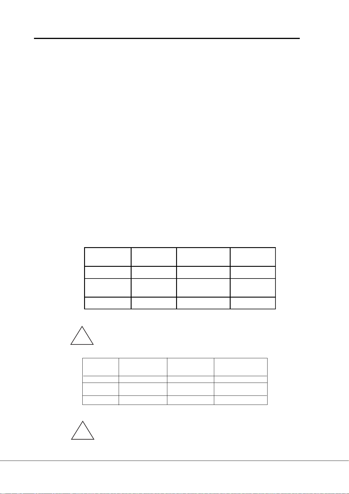
Frequency reference, analogue and digital
outputs have extra alternatives in their control
parameters. Source of free analogue input can
now be selected from the I/O Expander. These
inputs have also parameters for signal area
etc. programming.
11
11
1GeneralGeneral
GeneralGeneral
General
Multi-purpose II application is an extender
version of the normal Multipurpose application.
It has parameters for torque control and,
furthermore, for Fieldbus communication.
Following fieldbuses are supported: Interbus,
Modbus, Profibus, LonWorks, CAN-bus
(SDS, DeviceNet).
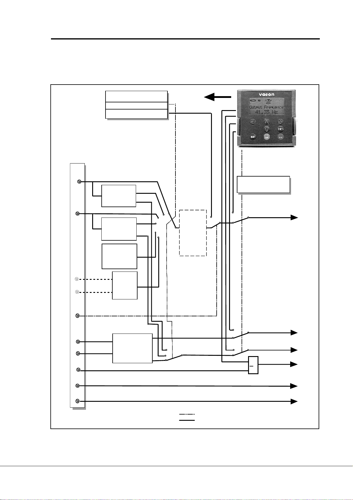
Terminal Signal Description
1 +10Vref Reference output Voltage for a potentiometer, etc.
2U
in+ Analogue input, Frequency reference
voltage (programmable) range 0—10 V DC
3 GND I/O ground Ground for reference and controls
4I
in+ Analogue input, Default setting: not used
5I
in- current (programmable) range 0—20 mA
6 +24V Control voltage output Voltage for switches, etc. max. 0.1 A
7 GND I/O ground Ground for reference and controls
8 DIA1 Start forward Contact closed = start forward
(programmable)
9 DIA2 Start reverse Contact closed = start reverse
(Programmable)
10 DIA3 Fault reset Contact open = no action
(programmable) Contact closed = fault reset
11 CMA Common for DIA1—DIA3 Connect to GND or + 24V
12 +24V Control voltage output Voltage for switches, (same as #6)
13 GND I/O ground Ground for reference and controls
14 DIB4 Jogging speed select Contact open = no action
(programmable) Contact closed = jogging speed
15 DIB5 External fault Contact open = no fault
(programmable) Contact closed = fault
16 DIB6 Accel./deceler. time select Contact open = par. 1.3, 1.4 in use
(programmable) Contact closed = par. 4.3, 4.4 in use
17 CMB Common for DIB4—DIB6 Connect to GND or + 24V
18 Iout+ Output frequency Programmable (par. 3..
..
.1)
19 Iout- Analogue output Range 0—20 mA/RLmax. 500 Ω
20 DO1 Digital output Programmable (par. 3..
..
.6)
READY Open collector, I<50 mA, U<48 VDC
21 RO1 Relay output 1 Programmable (par. 3..
..
.7)
22 RO1 RUN
23 RO1
24 RO2 Relay output 2 Programmable (par. 3..
..
.8)
25 RO2 FAULT
26 RO2
Figure 2-1 Default I/O configuration and connection example of the
Multi-purpose Control Application.

VV
VV
Vaconacon
aconacon
acon Page 3
Multi-purpose Control Application IIMulti-purpose Control Application II
Multi-purpose Control Application II
Vacon Plc Phone: +358-(0)2012121 Fax: +358-(0)201 212 205
Service: +358-40-8371150 E-mail: [email protected]
3 Control signal logic3 Control signal logic
3 Control signal logic
In figure 3-1 the logic of I/O-control signals and push button signals from the panel are presented.
Figure 3-1 Control signal logic of the Multipurpose II Application.
Switch positions correspond to factory settings.
DIB4
DIB5
DIA1
DIB6
DIA2
P
P
P
DIA3
UD012K05
>1
DIB5
DIB6
Internal
frequency
reference
Internal
Start/Stop
Internal
fault reset
Internal
reverse
= control line
=signal line
Programm.
Start/Stop
and Reverse
signal logic
PROGRAMMABLE
PUSH-BUTTON 2
Multi-step
speeds
(If any of
DI_ inputs
are pro-
grammed
for this
function)
Joystick
control
Joystick
control
Motorised
potentio-
meter
reference
Jogging speed selection
(programmable)
PARAMETERS
1.5 Reference selection
1.6 Jogging speed ref.
Up
Down
(programmable)
Fault reset
External fault
(programmable)
Accel./deceler. time select
(programmable)
Start REV.
Start FWD
Uin+
Iin±
Uin + Iin
Uin - Iin
I
in - Uin
Uin x Iin

Vacon Plc Phone: +358-(0)2012121 Fax: +358-(0)201 212 205
Service: +358-40-8371150 E-mail: [email protected]
Page 4 VV
VV
Vaconacon
aconacon
acon
Multi-purpose Control Application IIMulti-purpose Control Application II
Multi-purpose Control Application II
44
44
4Parameter group 0Parameter group 0
Parameter group 0Parameter group 0
Parameter group 0
Number Parameter Range Step Default Customer Description
0.1 Application
selection 0-7 1 0
0 = Multipurpose II (loaded special
application)
1 = Basic Application
2 = Standard Application
3 = Local/Remote Control
Application
4 = Multi-step Speed Application
5 = PI-control Application
6 = Multi-purpose Control
Application
7 = Pump and Fan Control
Application
0.2 Parameter loading 0-5 1 0
0 = Loading ready / Select loading
1 = Load default setting
2 = Read up parameters to user's
set
3 = Load down user's set
parameters
4 = Read parameters up to the
panel (possible only with graphical
panel)
5 = Load down parameters from
panel (possible only with graphical
panel)
0.3 Language selection 0-2 1 0
0 = English
1 = Germany
2 = Finnish
Table 4-1 Parameter group 0.
0.10.1
0.10.1
0.1 Application selectionApplication selection
Application selectionApplication selection
Application selection
With this parameter the active application can be selected. If the device has been
ordered from the factory equipped with Multipurpose II application this has been loaded
to the unit as application 0. The application has also been set active at the factory.
However, check that the value of the parameter 0.1 is zero when you want to use
Multipurpose II.
If the application should be loaded to the device later it has to be set active always after
loading by setting the value of parameter 0.1 to zero.
0.20.2
0.20.2
0.2 Parameter loadingParameter loading
Parameter loadingParameter loading
Parameter loading
See User's Manual chapter 11.
0.30.3
0.30.3
0.3 LanguageLanguage
LanguageLanguage
Language
With this parameter, the language of the graphical panel can be selected.

VV
VV
Vaconacon
aconacon
acon Page 5
Multi-purpose Control Application IIMulti-purpose Control Application II
Multi-purpose Control Application II
Vacon Plc Phone: +358-(0)2012121 Fax: +358-(0)201 212 205
Service: +358-40-8371150 E-mail: [email protected]
*) If 1..
..
.2 >motor synchr. speed, check suitability for motor and drive system.
Code Parameter Range Step Default Custom Description Page
1.1 Minimum frequency 0—120/500 Hz 1 Hz 0 Hz 6
1.2 Maximum frequency 0—120/500 Hz 1 Hz 50 Hz *) 6
1.3 Acceleration time 1 0.1—3000 s 0.1 s 3 s Time from fmin (1.1) to fmax (1.2) 6
1.4 Deceleration time 1 0.1—3000 s 0.1 s 3 s Time from fmax (1.2) to fmin (1.1) 6
1.5 Reference selection 0—15 1 0 0 = Uin 3 = Uin –Iin
1 = Iin 4 = Iin –Uin
2 = Uin + Iin 5 = Uin * Iin
6 = Uin joystick control
7 = Iin joystick control
8 = Signal from internal motor pot.
9 = Signal from internal motor pot.
reset if Vacon unit is stopped 6
10 = Signal from internal motor
pot. (stored in menory over
mains break
11= Min (Uin, Iin)
12 = Max (Uin, Iin)
13 = Panel reference r1
14 = Max reference
15 = Uin/Iin selection
1.6 Jogging speed
reference fmin –fmax
(1.1) (1.2) 0.1 Hz 5 Hz 7
1.7 Current limit 0.1—2.5 x InCX 0.1 A 1.5 x IcCX Output current limit [A] of the unit 7
1.8 U/f ratio selection 0—210 0 = Linear
1 = Squared
2 = Programmable U/f ratio 7
1.9 U/f optimisation 0—110 0 = None
1 = Automatic torque boost 8
1.10 Nominal voltage of the
motor 180—690 1 V
230 V
400 V
500 V
690 V
Vacon range CX/CXL2
Vacon range CX/CXL/CXS4
Vacon range CX/CXL/CXS5
Vacon range CX6
9
1.11 Nominal frequency of
the motor 30—500 Hz 1 Hz 50 Hz fnon the rating plate of the motor 9
1.12 Nominal speed of the
motor 300—20000 rpm 1 rpm 1440 rpm nnon the rating plate of the motor 9
1.13 Nominal current of the
motor 2.5 x InCX 0.1 A InCX Inon the rating plate of the motor 9
180—250 230 V Vacon range CX/CXL2
380—440 400 V Vacon range CX/CXL/CXS4
380—500 500 V Vacon range CX/CXL/CXS5
1.14 Supply voltage
525—690 690 V Vacon range CX6
9
1.15 Parameter conceal 0—110 0 = All parameter groups visible
1 = Only group 1 visible 9
1.16 Parameter value lock 0—110 0 = Parameter changes enabled
1 = parameter changes disabled 9
STOP
STOPSTOP
STOP
STOP
STOPSTOP
STOP
STOP
STOP
STOPSTOP
STOP
STOP
STOPSTOP
STOP
STOP
STOPSTOP
STOP
STOP
STOPSTOP
STOP
STOP
STOPSTOP
STOP
Note!Note!
Note!Note!
Note! STOP
STOPSTOP
STOP = Parameter value can be changed only when the frequency converter is stopped. (Continues)
Table 5-1. Group 1 basic parameters
55
55
5Basic Parameters, Group 1Basic Parameters, Group 1
Basic Parameters, Group 1Basic Parameters, Group 1
Basic Parameters, Group 1
5.15.1
5.15.1
5.1 Parameter tableParameter table
Parameter tableParameter table
Parameter table

Vacon Plc Phone: +358-(0)2012121 Fax: +358-(0)201 212 205
Service: +358-40-8371150 E-mail: [email protected]
Page 6 VV
VV
Vaconacon
aconacon
acon
Multi-purpose Control Application IIMulti-purpose Control Application II
Multi-purpose Control Application II
5.2 Description of Group 1 parameters5.2 Description of Group 1 parameters
5.2 Description of Group 1 parameters
1. 1, 1. 21. 1, 1. 2
1. 1, 1. 21. 1, 1. 2
1. 1, 1. 2 Minimum / maximum frequencyMinimum / maximum frequency
Minimum / maximum frequencyMinimum / maximum frequency
Minimum / maximum frequency
Defines frequency limits of the frequency converter.
The default maximum value for parameters 1..
..
.1 and 1..
..
.2 is 120 Hz. By setting 1..
..
. 2 =
120 Hz when the device is stopped (RUN indicator not lit) parameters 1..
..
.1 and 1..
..
.2
are changed to 500 Hz. At the same time the panel reference resolution is changed
from 0.01 Hz to 0.1 Hz.
Changing the max. value from 500 Hz to 120 Hz is done by setting the parameter
1..
..
.2 = 119 Hz when the device is stopped.
1. 3, 1. 41. 3, 1. 4
1. 3, 1. 41. 3, 1. 4
1. 3, 1. 4 Acceleration time 1, deceleration time 1:Acceleration time 1, deceleration time 1:
Acceleration time 1, deceleration time 1:Acceleration time 1, deceleration time 1:
Acceleration time 1, deceleration time 1:
These limits correspond to the time required for the output frequency to
accelerate from the set minimum frequency (par. 1..
..
.1) to the set maximum
frequency (par. 1..
..
. 2).
1. 51. 5
1. 51. 5
1. 5 Reference selectionReference selection
Reference selectionReference selection
Reference selection
00
00
0Analogue voltage reference from terminals 2—3, e.g. a potentiometer
11
11
1Analogue current reference trom terminals 4—5, e.g. a transducer.
22
22
2Reference is formed by adding the values of the analogue inputs
33
33
3Reference is formed by subtracting the voltage input (Uin) value
from the current input (Iin) value.
44
44
4Reference is formed by subtracting the current input (Iin ) value from the
voltage input (Uin) value.
55
55
5Reference is the formed by multiplying the values of the analogue inputs
66
66
6Joystick control from the voltage input (Uin).
WW
WW
Warning!arning!
arning!arning!
arning! Use only -10V—+10 V signal range. If a custom or 0—10 V signal
range is used, the drive starts to run at the max. reverse speed if the
reference signal is lost.
77
77
7Joystick control from the current input (Iin).
Signal range Max reverse Direction change Max forward
speed speed
0—20 mA 0 mA 10 mA 20 mA
Custom Par. 2..
..
.13 x 20 mA In the middle of Par. 2..
..
.14 x 20 mA
custom range
4—20 mA 4 mA 12 mA 20 mA
WW
WW
Warning!arning!
arning!arning!
arning! Use only 4—20 mA signal range. If custom or 0—20 mA signal range
is used, the drive runs at max. reverse speed if the control signal is lost.
Set the reference fault (par. 7..
..
. 2) active when the 4—20 mA range
is used, then the drive will stop to the reference fault if the reference
signal is lost.
!
!
Signal range Max reverse
speed Direction change Max forward
speed
0—10 V 0 V 5 V +10 V
Custom Par. 2.7 x 10 V In the middle of
custom range Par. 2.8 x 10 V
-10 V—+ 10 V -10 V 0 V +10 V

VV
VV
Vaconacon
aconacon
acon Page 7
Multi-purpose Control Application IIMulti-purpose Control Application II
Multi-purpose Control Application II
Vacon Plc Phone: +358-(0)2012121 Fax: +358-(0)201 212 205
Service: +358-40-8371150 E-mail: [email protected]
Note!Note!
Note!Note!
Note! When joystick control is used, the direction control is generated from joystick
reference signal. See figure 5.4-1.
Analogue input scaling, parameters 2..
..
.16—2..
..
. 19 are not used when joystick
control is used.
Fout
Uin
hystereesi +/-2% (+/-0,2 V)
+10V
-10V
Fmax
(par 1.2)
Fmin.
(par 1.1)
Fmin.
(par 1.1)
Fmax
(par 1.2)
Fout
Uin
Uin
+10V
-10V
Fmax
(par 1.2)
Fmax
(par 1.2)
If minimum frequency (par 1..
..
.1) >0, If minimum frequency (par 1..
..
.1) = 0,
hysteresis is ± 2% at reversing point. there is no hysteresis at reversing point.
Fig. 5-1 Joystick control Uin signal -10 V—+10 V.
88
88
8Reference value is changed with digital input signals DIB5 and DIB6.
- switch in DIB5 closed = frequency reference increases
- switch in DIB6 closed = frequency reference decreases
Speed of reference change can be set with the parameter 2..
..
.20.
99
99
9Same as setting 8 but the reference value is set to the minimum frequency
(par. 1..
..
.1) each time the frequency converter is stopped.
1010
1010
10 Same as setting 8 but the reference is stored to the memory over mains break.
When the value of the parameter 1..
..
.5 is set to 8, 9 or 10, the values of the
parameters 2..
..
.4 and 2..
..
. 5 are automatically set to 11.
11
11
111
11
1The minor of signals Uin and Iin is the frequency reference
1212
1212
12 The greater of signals Uin and Iin is the frequency reference
1313
1313
13 Panel reference r1 is the frequency reference
1414
1414
14 Maximum reference selection (recommended only at torque control)
1515
1515
15 Uin/Iin digital selection (see par. 2.3)
1. 61. 6
1. 61. 6
1. 6 Jogging speed referenceJogging speed reference
Jogging speed referenceJogging speed reference
Jogging speed reference
Parameter value defines the jogging speed selected with the digital input
1. 71. 7
1. 71. 7
1. 7 Current limitCurrent limit
Current limitCurrent limit
Current limit
This parameter determines the maximum motor current from the freqeuency
converter. To avoid motor overload, set this parameter according to the rated current
of the motor.
1. 81. 8
1. 81. 8
1. 8 U/f ratio selectionU/f ratio selection
U/f ratio selectionU/f ratio selection
U/f ratio selection
Linear: The voltage of the motor changes linearly with the frequency in the
00
00
0constant flux area from 0 Hz to the field weakening point (par. 6..
..
.3)
where the nominal voltage is also supplied to the motor. See figure
5-2. Linear U/f ratio should be used in constant torque applications.

Vacon Plc Phone: +358-(0)2012121 Fax: +358-(0)201 212 205
Service: +358-40-8371150 E-mail: [email protected]
Page 8 VV
VV
Vaconacon
aconacon
acon
Multi-purpose Control Application IIMulti-purpose Control Application II
Multi-purpose Control Application II
This default setting should be used if there is no special needThis default setting should be used if there is no special need
This default setting should be used if there is no special need
for another setting.for another setting.
for another setting.
Squared: The voltage of the motor changes following a squared curve form
11
11
1with the frequency in the area from 0 Hz to the field weakening
point (par. 6..
..
.3) where the nominal voltage is also supplied to
the motor. See figure 5-2.
The motor runs undermagnetised below the field weakening point
and produces less torque and electromechanical noise. Squared
U/f ratio can be used in applications where torque demand of
the load is proportional to the square of the speed, e.g. in centrifugal
fans and pumps.
Un
(Par 6.4)
(Par. 6. 3)
U[V]
f[Hz]
UD012K07
Default: Nominal
voltage of the motor
Linear
Squared
Field weakening
point
Default: Nominal
frequency of the
motor
Figure 5-2 Linear and squared U/f curves.
Programm. The U/f curve can be programmed with three different points.
U/f curve The parameters for programming are explained in chapter 5.2.
22
22
2Programmable U/f curve can be used if the other settings do not
satisfy the needs of the application. See figure 5-3.
Un
Par 6.4
Par. 6.3
U[V]
f[Hz]
UD012K08
Par. 6.5
(Def. 5 Hz)
Par. 6.6
(Def. 10%)
Par. 6.7
(Def. 1.3%)
Default: Nominal
voltage of the motor Field weakening
point
Default: Nominal
frequency of the
motor
Figure 5-3 Programmable U/f curve.
1.9 U/f optimisation1.9 U/f optimisation
1.9 U/f optimisation
Automatic The voltage to the motor changes automatically which makes the
torque motor produce sufficient torque to start and run at low frequencies. The
boost voltage increase depends on the motor type and power.
Automatic torque boost can be used in applications where starting
torque due to starting friction is high, e.g. in conveyors.

VV
VV
Vaconacon
aconacon
acon Page 9
Multi-purpose Control Application IIMulti-purpose Control Application II
Multi-purpose Control Application II
Vacon Plc Phone: +358-(0)2012121 Fax: +358-(0)201 212 205
Service: +358-40-8371150 E-mail: [email protected]
NOTE! In high torque - low speed applications - it is likely the motor will
overheat.
If the motor has to run a prolonged time under these
conditions,
special attention must be paid to cooling the motor. Use external
cooling for the motor if the temperature tends to rise too high.
1. 101. 10
1. 101. 10
1. 10 Nominal voltage of the motorNominal voltage of the motor
Nominal voltage of the motorNominal voltage of the motor
Nominal voltage of the motor
Find this value Unon the rating plate of the motor.
This parameter sets the voltage at the field weakening point, parameter 6..
..
. 4, to
100% x Unmotor.
1. 11. 1
1. 11. 1
1. 111
11
1Nominal frequency of the motorNominal frequency of the motor
Nominal frequency of the motorNominal frequency of the motor
Nominal frequency of the motor
Find this value fnon the rating plate of the motor.
This parameter sets the field weakening point, parameter 6. 3, to the same value.
1. 121. 12
1. 121. 12
1. 12 Nominal speed of the motorNominal speed of the motor
Nominal speed of the motorNominal speed of the motor
Nominal speed of the motor
Find this value nnon the rating plate of the motor.
1. 131. 13
1. 131. 13
1. 13 Nominal current of the motorNominal current of the motor
Nominal current of the motorNominal current of the motor
Nominal current of the motor
Find this value Inon the rating plate of the motor.
1. 141. 14
1. 141. 14
1. 14 Supply voltageSupply voltage
Supply voltageSupply voltage
Supply voltage
Set parameter value according to the nominal voltage of the supply.
Values are predefined for CX/CXL2, CX/CXL/CXS4, CX/CXL/CXS5 and CX6
ranges, see table 5-1.
1. 151. 15
1. 151. 15
1. 15 Parameter concealParameter conceal
Parameter concealParameter conceal
Parameter conceal
Defines which parameter groups are available for editing:
0 = all parameter groups are visible
1 = only group 1 is visible
1. 161. 16
1. 161. 16
1. 16 Parameter value lockParameter value lock
Parameter value lockParameter value lock
Parameter value lock
Defines access to the changes of the parameter values:
0 = parameter value changes enabled
1 = parameter value changes disabled
!

Vacon Plc Phone: +358-(0)2012121 Fax: +358-(0)201 212 205
Service: +358-40-8371150 E-mail: [email protected]
Page 10 VV
VV
Vaconacon
aconacon
acon
Multi-purpose Control Application IIMulti-purpose Control Application II
Multi-purpose Control Application II
Note!Note!
Note!Note!
Note! = Parameter value can be changed only when the frequency converter is stopped. (Continues)
Code Parameter Range Step Default Description Page
DIA1 DIA2
2.1 Start/Stop logic
selection 0—41 0
0 = Start forw.
1 = Start/Stop
2 = Start/Stop
3 = Start pulse
4 = Start/stop pulse
Start reverse
Reverse
Run enable
Stop pulse
Run enable
19
2.2 DIA3 function
(terminal 10) 0—12 1 7
0 = Not used
1 = External fault, closing contact
2 = External fault, opening contact
3 = Run enable
4 = Accel./decel. time selection
5 = Reverse
6 = Jogging speed
7 = Fault reset
8 = Accel./decel. operation prohibit
9 = DC-braking command
10 = Torque control
11 = Torque reference sign
12 = Run enable with coasting
20
2.3 DIB4 function
(terminal 14) 0—15 1 6
0 = Not used
1 = External fault, closing contact
2 = External fault, opening contact
3 = Run enable
4 = Accel./decel. time selection
5 = Reverse
6 = Jogging speed
7 = Fault reset
8 = Accel./decel. operation prohibit
9 = DC-braking command
10 = Multi-step speed select 1
11 = Selection between Iin and Uin
12 = Run enable with coasting
13 = Fieldbus control
14 = Par. 1.5 / Uin
15 = Par. 1.5 / Iin
22
2.4 DIB5 function
(terminal 15) 0—13 1 1
0 = Not used
1 = External fault, closing contact
2 = External fault, opening contact
3 = Run enable
4 = Accel./decel. time selection
5 = Reverse
6 = Jogging speed
7 = Fault reset
8 = Accel./decel. operation prohibit
9 = DC-braking command
10 = Multi-step speed select 2
11 = Motorised pot. speed up
12 = Run enable with coasting
13 = Fieldbus control
22
2.5 DIB6 function
(terminal 16) 0—13 1 4
0 = Not used
1 = External fault, closing contact
2 = External fault, opening contact
3 = Run enable
4 = Accel./decel. time selection
5 = Reverse
6 = Jogging speed
7 = Fault reset
8 = Accel./decel. operation prohibit
9 = DC-braking command
10 = Multi-step speed select 3
11 = Motorised pot. speed down
12 = Run enable with coasting
13 = Fieldbus control
22
STOP
STOPSTOP
STOP
STOP
STOPSTOP
STOP
STOP
STOPSTOP
STOP
STOP
STOPSTOP
STOP
STOP
STOPSTOP
STOP
66
66
6Special Parameters, Groups 2—10Special Parameters, Groups 2—10
Special Parameters, Groups 2—10Special Parameters, Groups 2—10
Special Parameters, Groups 2—10
6.16.1
6.16.1
6.1 Parameter tablesParameter tables
Parameter tablesParameter tables
Parameter tables
Group 2, Input signal parametersGroup 2, Input signal parameters
Group 2, Input signal parameters
STOP
STOPSTOP
STOP

VV
VV
Vaconacon
aconacon
acon Page 11
Multi-purpose Control Application IIMulti-purpose Control Application II
Multi-purpose Control Application II
Vacon Plc Phone: +358-(0)2012121 Fax: +358-(0)201 212 205
Service: +358-40-8371150 E-mail: [email protected]
Code Parameter Range Step Default Custom Description Page
2. 6 Uin signal range 0—2 1 0 0 = 0—10 V
1 = Custom setting range
2 = -10—+10 V (can be used with
Joystick control only)
2..
..
. 7U
in custom setting min. 0—100% 0.01% 0.00% 22
2..
..
. 8U
in custom setting max. 0—100% 0.01% 100.00% 22
2..
..
. 9U
in signal inversion
0
—
1
1 0 0 = Not inverted 22
1 = Inverted
2..
..
.10 Uin signal filter time
0—10s
0.01s 0.1s 0 = No filtering 22
2..
..
.11 Iin signal range 0—210 0=0—20 mA 23
1 = 4—20 mA
2 = Custom setting range
2..
..
.12 Iin custom setting minim. 0—100% 0.01% 0.00% 23
2..
..
.13 Iin custom setting maxim. 0—100% 0.01% 100.00% 23
2..
..
.14 Iin signal inversion
0
—
1
1 0 0 = Not inverted 23
1 = Inverted
2..
..
. 15 Iin signal filter time
0—10s
0.01s 0.1s 0 = No filtering 23
2..
..
.16 Uin minimum scaling -320,00%—0% 0,01 0% = no minimum scaling 23
+320,00 %
2..
..
.17 Uin maximum scaling -320,00%—100% 0,01 100% = no maximum scaling 23
+320,00 %
2..
..
.18 Iin minimum scaling -320,00%—0% 0,01 0% = no minimum scaling 23
+320,00 %
2..
..
.19 Iin maximum scaling -320,00%—100% 0,01 100% = no maximum scaling 23
+320,00 %
2..
..
. 20 Free analogue input, 0—5 1 0 0 = Not use 24
signal selection 1 = Uin (analogue voltage input)
2 = Iin (analogue current input)
3 = Ain1 (option board)
4 = Ain2 (option board)
5 = Fieldbus signal
2..
..
.21 Free analogue input, 0—4 1 0 0 = No function 24
function 1 = Reduces current limit (par. 1..
..
.7)
2 = Reduces DC-braking current
3 = Reduces acc. and decel. times
4 = Reduces torque supervis. limit
2..
..
.22 Motorised potentiometer 0.1—2000.0 0.1 10.0 25
ramp time Hz/s Hz/s Hz/s
2..
..
. 23 Option board Ain1 signal 0—1 1 0 0 = Not inverted 25
inversion 1 = Inverted
2..
..
.24 Option board Ain1 signal 0—10s 0.01s 0.1s 0 = No filtering 25
filter time
2..
..
.25 Option board Ain2 signal 0—210 0=0—20 mA 25
signal range 1 = 4—20 mA
2 = 0—10 V
2..
..
.26 Option board Ain2 signal 0—1 1 0 0 = Not inverted 25
inversion 1 = Inverted
2..
..
. 27 Option board Ain2 signal 0 —10s 0.01s 0.1s 0 = No filtering 25
filter time
Note!Note!
Note!Note!
Note! STOP
STOPSTOP
STOP = Parameter value can be changed only when the frequency converter is stopped. (Continues)

Vacon Plc Phone: +358-(0)2012121 Fax: +358-(0)201 212 205
Service: +358-40-8371150 E-mail: [email protected]
Page 12 VV
VV
Vaconacon
aconacon
acon
Multi-purpose Control Application IIMulti-purpose Control Application II
Multi-purpose Control Application II
Code Parameter Range Step Default Custom Description Page
2.28 Adjust Input 0 - 5 1 0 0 = Not used
1 = Voltage input
2 = Current input
3 = AIN1 I/O-expand
4 = AIN2 I/O-expand
5 = FB signal
2.29 Adjust Percentage 0.0% - 200.0% 0.1% 0.0%
2.30 Adjust Offset 0.0% - 100.0% 0.1% 0.0%
Note!Note!
Note!Note!
Note! STOP
STOPSTOP
STOP = Parameter value can be changed only when the frequency converter is stopped.

VV
VV
Vaconacon
aconacon
acon Page 13
Multi-purpose Control Application IIMulti-purpose Control Application II
Multi-purpose Control Application II
Vacon Plc Phone: +358-(0)2012121 Fax: +358-(0)201 212 205
Service: +358-40-8371150 E-mail: [email protected]
Note!Note!
Note!Note!
Note! STOP
STOPSTOP
STOP = Parameter value can be changed only when the frequency converter is stopped. (Continues)
Code Parameter Range Step Default C
u
s
t
o
m
Description Page
3.1 Analogue output func-
tion 0—14 1 1
0 = Not used
1 = O/P frequency
2 = Motor speed
3 = O/P current
4 = Motor torque
5 = Motor power
6 = Motor voltage
7 = DC-link volt.
8 = Input signal Uin
9 = Input signal Iin
10 = Refer. freq.
11 = Refer. torque
12 = Motor±torque
13 = Motor±power
14 = O/P freq.
Scale 100%
(0—fmax)
(0—max. speed
(0—2.0 x InCX)
(0—2 x TnCX)
(0—2 x PnCX)
(0—100% x UnM)
(0—1000 V)
(-2--+2xTnMOT)
(-2--+2xTnMOT)
(fmin—fmax)
26
3.2 Analogue output filter
time 0.01—10 s 0.01 1.00 26
3.3 Analogue output inver-
sion 0—11 0 0 = Not inverted
1 = Inverted 26
3.4 Analogue output mini-
mum 0—11 0 0 = 0 mA
1 = 4 mA 26
3.5 Analogue output scale 10—1000% 1% 100% 26
3.6 Digital output function 0—22 1 1
0 = Not used
1 = Ready
2 = Run
3 = Fault
4 = Fault inverted
5 = Vacon overheat warning
6 = External fault or warning
7 = Reference fault or warning
8 = Warning
9 = Reversed
10 = Jogging speed selected
11 = At speed
12 = Motor regulator activated
13 = Output frequency limit superv. 1
14 = Output frequency limit superv. 2
15 = Torque limit supervision
16 = Reference limit supervision
17 = External brake control
18 = Control from I/O terminals
19 = Frequency converter temperature
limit supervision
20 = Unrequested rotation direction
21 = External brake control inverted
22 = Termistor fault or warning
27
3.7 Relay output 1 function 0—22 1 2 As parameter 3.6 27
3.8 Relay output 2 function 0—22 1 3 As parameter 3.6 27
3.9 Output frequency limit 1
supervision function 0—21 0 0 = No
1 = Low limit
2 = High limit
27
3.10 Output frequency limit 1
supervision value
0—fmax
(par. 1.2) 0.1 Hz 0 Hz 27
3.11 Output frequency limit 2
supervision function 0—21 0 0 = No
1 = Low limit
2 = High limit 27
3.12 Output frequency limit 2
supervision value 0—fmax
(par. 1.2) 0.1 Hz 0 Hz 27
STOP
STOPSTOP
STOP
STOP
STOPSTOP
STOP
STOP
STOPSTOP
STOP
Group 3, Output and supervision parametersGroup 3, Output and supervision parameters
Group 3, Output and supervision parameters

Vacon Plc Phone: +358-(0)2012121 Fax: +358-(0)201 212 205
Service: +358-40-8371150 E-mail: [email protected]
Page 14 VV
VV
Vaconacon
aconacon
acon
Multi-purpose Control Application IIMulti-purpose Control Application II
Multi-purpose Control Application II
Code Parameter Range Step Default Custom Description Page
3..
..
.13 Torque limit 0—2 1 0 0 = No 28
supervision function 1 = Low limit
2 = High limit
3..
..
.14 Torque limit 0—200% 1% 100% 28
supervision value xTnCX
3..
..
.15 Reference limit 0—2 1 0 0 = No 28
supervision function 1 = Low limit
2 = High limit
3..
..
.16 Reference limit 0—fmax 0.1 Hz 0 Hz 28
supervision value (par. 1..
..
.2)
3..
..
.17 Extern. brake Off-delay 0—100.0 s 0.1 s 0.5 s 28
3..
..
.18 Extern. brake On-delay 0—100.0 s 0.1 s 1.5 s 28
3..
..
.19 Frequency converter 0—2 1 0 0 = No 28
temperature limit 1 = Low limit
supervision function 2 = High limit
3..
..
.20 Frequency converter -10—+75°C1°C +40°C28
temperature limit value
3..
..
.21 I/O-expander board (opt.) 0—14 1 3 See parameter 3..
..
.1 –
analogue output content
3..
..
.22 I/O-expander board (opt.) 0.01—10 s 0.01 1.00 See parameter 3..
..
.2 –
analogue output filter time
3..
..
.23 I/O-expander board (opt.) 0—1 1 0 See parameter 3..
..
.3 –
analogue output inversion
3..
..
.24 I/O-expander board (opt.) 0—1 1 0 See parameter 3..
..
.4 –
analogue output minimum
3..
..
.25 I/O-expander board (opt.) 10—1000% 1 100% See parameter 3..
..
.5 –
analogue output scale
3. 26 Analog output offset -100—1 100% 29
(basic control board) 100,0%
3. 27 I/O-expander board (opt.) -100—1 100% 29
analogue output offset +100,0%
3..
..
.28 Digital output DO1 0—320,00s 0,01 0,00 0,00 = delay not in use 29
on delay
3..
..
.29 Digital output DO1 0—320,00s 0,01 0,00 0,00 = delay not in use 29
off delay
3..
..
.30 Relay output RO1 0—320,00s 0,01 0,00 0,00 = delay not in use 29
on delay
3..
..
.31 Relay output RO1 0—320,00s 0,01 0,00 0,00 = delay not in use 29
off delay
3..
..
.32 Relay output RO1 0—320,00s 0,01 0,00 0,00 = delay not in use 29
on delay
3.33 Relay output RO2 0—320,00s 0,01 0,00 0,00 = delay not in use 29
off delay

VV
VV
Vaconacon
aconacon
acon Page 15
Multi-purpose Control Application IIMulti-purpose Control Application II
Multi-purpose Control Application II
Vacon Plc Phone: +358-(0)2012121 Fax: +358-(0)201 212 205
Service: +358-40-8371150 E-mail: [email protected]
Group 4, Drive control parametersGroup 4, Drive control parameters
Group 4, Drive control parameters
Code Parameter Range Step Default Custom Description Page
4..
..
. 1 Acc./Dec. ramp 1 shape 0—10 s 0.1 s 0 0 = Linear 30
>0 = S-curve acc./dec. time
4..
..
. 2 Acc./Dec. ramp 2 shape 0—10 s 0.1 s 0 0 = Linear 30
>0 = S-curve acc./dec. time
4..
..
. 3 Acceleration time 2 0.1—3000 s 0.1 s 10 s 31
4..
..
. 4 Deceleration time 2 0.1—3000 s 0.1 s 10 s 31
4..
..
.5 Brake chopper 0—1 1 0 0 = Brake chopper not in use 31
1 = Brake chopper in use
2 = External brake chopper
4..
..
.6 Start function 0—1 1 0 0 = Ramp 31
1 = Flying start
4..
..
. 7 Stop function 0—1 1 0 0 = Coasting 31
1 = Ramp
4..
..
. 8 DC-braking current 0.15—1.5 0.1 A 0.5 x InCX 31
x InCX (A)
4..
..
. 9 DC-braking time at Stop 0—250.0 s 0.1 s 0 s 0 = DC-brake is off at Stop 32
4..
..
. 10 Execute freq. of DC- 0.1—10 Hz 0.1 Hz 1.5 Hz 33
brake during ramp Stop
4..
..
. 11 DC-brake time at Start 0.0—25.0 s 0.1 s 0 s 0 = DC-brake is off at Start 33
4..
..
.12 Multi-step speed fmin —fmax 0.1 Hz 10 Hz 33
reference 1 (1..
..
.1) (1..
..
.2)
4..
..
.13 Multi-step speed fmin —fmax 0.1 Hz 15 Hz 33
reference 2 (1..
..
.1) (1..
..
.2)
4..
..
.14 Multi-step speed fmin —fmax 0.1 Hz 20 Hz 33
reference 3 (1..
..
.1) (1..
..
.2)
4..
..
.15 Multi-step speed fmin —fmax 0.1 Hz 25 Hz 33
reference 4 (1..
..
.1) (1..
..
.2)
4..
..
.16 Multi-step speed fmin —fmax 0.1 Hz 30 Hz 33
reference 5 (1..
..
.1) (1..
..
.2)
4..
..
.17 Multi-step speed fmin —fmax 0.1 Hz 40 Hz 33
reference 6 (1..
..
.1) (1..
..
.2)
4..
..
.18 Multi-step speed fmin —fmax 0.1 Hz 50 Hz 33
reference 7 (1..
..
.1) (1..
..
.2)
Note!Note!
Note!Note!
Note! = Parameter value can be changed only when the frequency converter is stopped.
STOP
STOPSTOP
STOP
STOP
STOPSTOP
STOP

Vacon Plc Phone: +358-(0)2012121 Fax: +358-(0)201 212 205
Service: +358-40-8371150 E-mail: [email protected]
Page 16 VV
VV
Vaconacon
aconacon
acon
Multi-purpose Control Application IIMulti-purpose Control Application II
Multi-purpose Control Application II
STOP
STOPSTOP
STOP
STOP
STOPSTOP
STOP
Group 5, Prohibit frequency parametersGroup 5, Prohibit frequency parameters
Group 5, Prohibit frequency parameters
Code Parameter Range Step Default Custom Description Page
5..
..
. 1 Prohibit frequency 0—fmax 0.1 Hz 0 Hz 33
range 1 low limit (1..
..
.2)
5..
..
.2 Prohibit frequency 0—fmax 0.1 Hz 0 Hz 0 = Prohibit range 1 is off 33
range 1 high limit (1..
..
.2)
5..
..
. 3 Prohibit frequency 0—fmax 0.1 Hz 0 Hz 33
range 2 low limit (1..
..
.2)
5..
..
.4 Prohibit frequency 0—fmax 0.1 Hz 0 Hz 0 = Prohibit range 2 is off 33
range 2 high limit (1..
..
.2)
5..
..
. 5 Prohibit frequency 0—fmax 0.1 Hz 0 Hz 33
range 3 low limit (1..
..
.2)
5..
..
.6 Prohibit frequency 0—fmax 0.1 Hz 0 Hz 0 = Prohibit range 3 is off 33
range 3 high limit (1..
..
.2)
Group 6, Motor control parametersGroup 6, Motor control parameters
Group 6, Motor control parameters
Code Parameter Range Step Default Custom Description Page
6..
..
. 1 Motor control mode 0—2 1 0 0 = Frequency control 33
1 = Speed control (open loop)
2 = Torque control (open loop)
6..
..
. 2 Switching frequency 1—16 kHz 0.1 kHz 10/3.6 kHz Dependant on kW 34
6..
..
. 3 Field weakening point 30—500 Hz 1 Hz Param. 34
1..
..
.11
6..
..
.4 Voltage at field 15 —200% 1% 100% 34
weakening point x Unmot
6..
..
. 5 U/F-curve mid 0—500 Hz 0,1 Hz 0 Hz 34
point frequency
6..
..
. 6 U/F-curve mid 0—100% 0.01% 0 % 34
point voltage x Unmot
6..
..
. 7 Output voltage at 0—100% 0.01% 0 % 34
zero frequency x Unmot
6..
..
. 8 Overvoltage controller 0—1 1 1 0 = Controller is not operating 35
1 = Controller is operating
6..
..
.9 Undervoltage controller 0—1 1 1 0 = Controller is not operating 35
1 = Controller is operating
Note!Note!
Note!Note!
Note!
STOP
STOPSTOP
STOP = Parameter value can be changed only when the frequency converter is stopped.
STOP
STOPSTOP
STOP
STOP
STOPSTOP
STOP
STOP
STOPSTOP
STOP
STOP
STOPSTOP
STOP
STOP
STOPSTOP
STOP

VV
VV
Vaconacon
aconacon
acon Page 17
Multi-purpose Control Application IIMulti-purpose Control Application II
Multi-purpose Control Application II
Vacon Plc Phone: +358-(0)2012121 Fax: +358-(0)201 212 205
Service: +358-40-8371150 E-mail: [email protected]
Group 7, ProtectionsGroup 7, Protections
Group 7, Protections
Code Parameter Range Step Default Custom Description Page
7..
..
. 1 Response to 0—3 1 0 0 = No action 35
reference fault 1 = Warning
2 = Fault, stop according to
par 4.7
3 = Fault, stop always by coasting
7..
..
. 2 Response to 0—3 1 2 0 = No action 35
external fault 1 = Warning
2 = Fault, stop according to par 4.7
3 = Fault, stop always by coasting
7..
..
. 3 Phase supervision of 0—2 1 2 0 = No action 35
the motor 1 = Warning
2 = Fault
7..
..
. 4 Earth fault protection 0—2 1 2 0 = No action 35
1 = Warning
2 = Fault
7..
..
. 5 Motor thermal protection 0—2 1 2 0 = No action 36
1 = Warning
2 = Fault
7..
..
.6
Motor thermal
protection 50.0—150 % 1.0 % 100.0% 36
break point current x InMOTOR
7..
..
.7
Motor thermal
protection 10.0—150% 1.0 % 45.0% 37
zero frequency current xInMOTOR
7..
..
.8
Motor thermal
protection 0.5—300.0 0,5 Default value is set according 37
time constant minutes min. to motor nominal current
7..
..
.9
Motor thermal
protection 10—500 Hz 1 Hz 35 Hz 38
break point frequency
7..
..
.10 Stall protection 0—2 1 1 0 = No action 38
1 = Warning
2 = Fault
7..
..
.11 Stall current limit 10.0—200% 1.0% 130.0% 39
x InMOTOR
7..
..
.12 Stall time 2.0—120 s 1.0 s 15.0 s 39
7..
..
.13 Maximum stall frequency 1—fmax 1 Hz 25 Hz 39
7..
..
.14 Underload protection 0—2 1 0 0 = No action 40
1 = Warning
2 = Fault
7..
..
.15 Underload prot., field 20.0—150 % 1.0% 50.0% 40
weakening area load x TnMOTOR
7..
..
.16 Underload protection, 10.0—150.0% 1.0% 10.0% 40
zero frequency load xTnMOTOR
7..
..
.17 Underload time 2.0—600.0 s 1.0 s 20.0s 40
7..
..
. 18 Phase supervision of 0—2 1 2 0 = No action 41
the supply voltage 1 = Warning
2 = Fault
7..
..
. 19 Termistor input of 0—2 1 2 0 = No action 41
I/O-Expander 1 = Warning
2 = Fault
7.20 Response to fieldbus 0
—
2 1 0 0 = Not used 41
fault 1 = Warning
2 = Fault

Vacon Plc Phone: +358-(0)2012121 Fax: +358-(0)201 212 205
Service: +358-40-8371150 E-mail: [email protected]
Page 18 VV
VV
Vaconacon
aconacon
acon
Multi-purpose Control Application IIMulti-purpose Control Application II
Multi-purpose Control Application II
2 = Fault
Group 8, Autorestart parametersGroup 8, Autorestart parameters
Group 8, Autorestart parameters
Code Parameter Range Step Default Custom Description Page
8..
..
.1 Automatic restart: 0—10 1 0 0 = not in use 41
number of tries
8..
..
. 2 Automatic restart: 1—6000 s 1 s 30 s 41
trial time
8..
..
.3 Automatic restart: 0—1 1 0 0 = Ramp 42
start function 1 = Flying start
8..
..
.4 Automatic restart of 0—1 1 0 0 = No 42
undervoltage 1 = Yes
8..
..
.5 Automatic restart of 0—1 1 0 0 = No 42
overvoltage 1 = Yes
8..
..
.6 Automatic restart of 0—1 1 0 0 = No 42
overcurrent 1 = Yes
8..
..
. 7 Automatic restart of 0—1 1 0 0 = No 42
reference fault 1 = Yes
8..
..
.8 Automatic restart after 0—1 1 0 0 = No 42
over/undertemperature 1 = Yes
fault
Group 9, TGroup 9, T
Group 9, Torque Controlorque Control
orque Controlorque Control
orque Control
Code Parameter Range Step Default Custom Description Page
9.1 Torque reference
selection 0—610
0 = None
1 = Uin
2 = Iin
3 = Panel Trq reference r2
4 = Ain1 (option board)
5 = Ain2 (option board)
6 = Fieldbus control
43
9.2 Torque reference
scaling bias –100%--
+100% 1 0 0 = Not in use 43
9.3 Torque reference
scaling gain –320%--
+320% 1 100 100 = No scaling 43
9.4 TC time constant 1—1000 ms 1 ms 15 ms 43
9.5 TC minimum control
limit 0—10.00 Hz 0.01
Hz 3.00 Hz 43

VV
VV
Vaconacon
aconacon
acon Page 19
Multi-purpose Control Application IIMulti-purpose Control Application II
Multi-purpose Control Application II
Vacon Plc Phone: +358-(0)2012121 Fax: +358-(0)201 212 205
Service: +358-40-8371150 E-mail: [email protected]
Group 10, Fieldbus parametersGroup 10, Fieldbus parameters
Group 10, Fieldbus parameters
Code Parameter Range Step Default Custom Description Page
10..
..
.1 Fieldbus control select 0—1 1 0 0 = Control via I/O terminals 44
1 = Control via Fieldbus board
10..
..
. 2 DIC1 function 0—1 0 1 0 = Fieldbus control 44
(term. 301, fieldbus board) 1 = External fault
10..
..
.3 MODBUS Slave address 1—247 1 1 44
10..
..
.4 Baud rate 1—7 1 6 1 = 300 baud 44
2 = 600 baud
3 = 1200 baud
4 = 2400 baud
5 = 4800 baud
6 = 9600 baud
7 = 19200 baud
10..
..
.5 MB Parity type 0—2 1 0 0 = None 44
1 = Even
2 = Odd
10..
..
.6 Modbus time-out 0—3600 s 1 s 0 s 0 = No time-out 44
10.7 Profibus slave address 2—126 1 126 44
10.8 Profibus baud rate 1—10 1 10 1 = 9.6 kbaud 45
2 = 19.2 kbaud
3 = 93.75 kbaud
4 = 187.5 kbaud
5 = 500 kbaud
6 = 1.5 Mbaud
7 = 3 Mbaud
8 = 6 Mbaud
9 = 12 Mbaud
10 = AUTO
10.9 Profibus PPO Type 1—4 1 1 1 = PPO 1 45
2 = PPO 2
3 = PPO 3
4 = PPO 4
10.10 Profibus Process Data 1 0—99 1 1 45
10.11. Profibus Process Data 2 0—99 1 2 45
10.12 Profibus Process Data 3 0—99 1 3 45
10.13 Profibus Process Data 4 0—99 1 99 45
10.14 LonWorks Service Button 0—110 45
Table 6-1. Special parameters, Groups 2-10
Other manuals for CX
5
This manual suits for next models
2
Table of contents
Other Vacon Media Converter manuals
Popular Media Converter manuals by other brands

Ensemble Designs
Ensemble Designs BrightEye 90-FA user guide

AJA
AJA FiDO 3G Series Installation and operation guide

SIIG
SIIG AV-GM08V3-S1 manual

Lika
Lika Posicontrol IF55 LIN CB Series Mounting instructions

PreppComm
PreppComm MMX quick start guide

Transition Networks
Transition Networks SSDTF3011-115 user guide