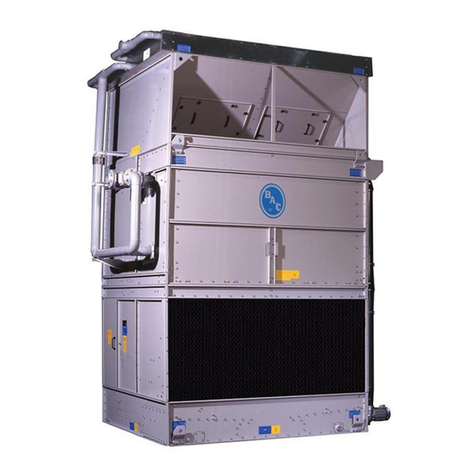
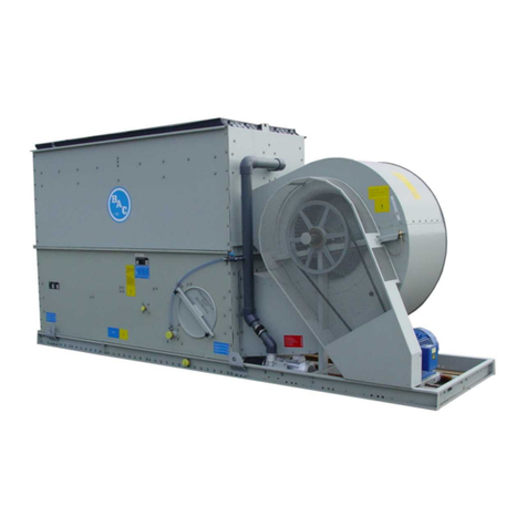
BAC 3240C Manual

OPERATION & MAINTENANCE MANUAL
Series 3000 Cooling Tower

DANGER: Do not perform any
service on or near the fans,
motors, and drives, or inside
the unit without first ensuring
that the fans and pumps are
disconnected, locked out, and
tagged out.
NOTES:
1. Recommended service intervals are the minimum for typical installations. Different
environmental conditions may dictate more frequent servicing. Follow all safety and
equipment precautions on pages 2 and 3.
2. When operating in ambient temperatures below freezing, the unit should be inspected
more frequently. Refer to “Cold Weather Operation” on page 28 for more details.
3. Tension on new belts must be readjusted after the first 24 hours of operation and
quarterly, thereafter.
4. Lubricate fan shaft bearings quarterly or every 2,000 hours of operation, whichever
occurs first.
Recommended Maintenance Service[1]
Inspect and clean as necessary: Start-Up Monthly Quarterly Annually Shutdown
Inspect general condition of the unit[2] and check unit for unusual
noise or vibration
Inspect cold and hot water basins
Flush water distribution system/Inspect spray nozzles
Drain basin and piping
Inspect air intake louvers/Combined inlet shields
Check and adjust water level in cold water basin
Check operation of make-up valve
Check and adjust bleed rate
Check optional EASY CONNECT®Piping Arrangement
Inspect unit finish
Mechanical equipment system: Start-Up Monthly Quarterly Annually Shutdown
Check belt condition
Adjust belt tension[3]
Lubricate fan shaft bearings[4} [4]
Lubricate motor base adjusting screw
Check and lubricate optional gear drive See gear drive section on page 13 for detailed instructions and schedule.
Check drive alignment
Check motor voltage and current
Clean fan motor exterior
Check fan motor for proper rotation
Check general condition of the fan
Check and unplug fan drain holes (hollow blade fans)
Check fan for uniform pitch
Check fan for rotation without obstruction
Check and recoat steel shafts with RUST VETO®
Check optional basin heater and stand alone BAC heater control panel
Check optional vibration cutout switch

Table of Contents
Safety and Equipment Precautions
2Danger
2Warning
2Caution
2Warranties
3Attention
3General Maintenance Information
PART 1 Unit Operation and Storage
4Start-Up Procedure
6Extended Shutdown
7Prolonged Outdoor Storage
PART 2 Detailed Component Maintenance Procedures
9Cold Water Basin
10 Fan
11 Fan Drive System
17 Fan Motors
17 Fan Shaft Bearings
18 Heat Transfer Section
18 Water Distribution System
19 Water Level Control
PART 3 Corrosion Protection
22 Water Treatment
23 Corrosion and Scale Control
23 Biological Control
24 Chemical Treatment Requirements
24 Passivation
25 Long Term Care of Stainless Steel
PART 4 Bleed Rate
26 Bleed Rate
PART 5 Cold Weather Operation
28 Inspection & Maintenance
28 Fan Section Icing Protection
29 Basin Water and Internal Piping Freeze Protection
30 Freeze Protection for the Optional EASY CONNECT®
Piping Arrangement
PART 6 Operation Considerations for Accessories
31 Basin Heater (Optional)
32 Vibration Cutout Switch (VCOS)
33 Stand Alone BAC Heater Control Panel (Optional)
Part 7 Fan Control
35 Variable Frequency Drive Operation
36 Resonant Speed Identification Procedure
PART 8 New Field Connections for TriArmor®
Corrosion Protection System Cold Water
Basin
38 Installation Instructions
OPERATION & MAINTENANCE » SERIES 3000 COOLING TOWER
1
WWW.BALTIMOREAIRCOIL.COM

2
WWW.BALTIMOREAIRCOIL.COM
Danger
• DANGER: Do not perform any service on or near the fans, motors, and drives, or inside the unit without first ensuring that the fans and
pumps are disconnected, locked out, and tagged out.
• WARNING: When access to the top of the unit is desired, the purchaser/end-user is cautioned to use appropriate means to comply with
applicable safety standards related to working on elevated surfaces.
• WARNING: When the fan speed of the unit is to be changed from the factory set speed, including changes achieved by the use of a
variable fan speed device, steps must be taken to avoid operation at or near the fan’s “critical speed” which could result in fan failure
and possible personal injury or damage.
• WARNING: The recirculating water system may contain chemicals or biological contaminants, including Legionella, which could
be harmful if inhaled or ingested. Personnel exposed directly to the discharge airstream and the associated drift mists, generated
during operation of the water distribution system and/or fans, or mists produced by high pressure water jets or compressed air (if
used to clean components of the recirculating water system), must wear respiratory protection equipment approved for such use by
governmental occupational safety and health authorities.
• WARNING: All electrical, mechanical, and rotating machinery are potential hazards, particularly for those not familiar with their design,
construction, and operation. Accordingly, use appropriate lockout procedures. Adequate safeguards (including the use of protective
enclosures where necessary) should be taken with this equipment both to safeguard the public from injury and to prevent damage to
the equipment, its associated system, and the premises.
• WARNING: A lockable disconnect switch should be located within sight of the unit for each fan motor associated with this equipment.
Before performing any type of service of inspection, make certain that all power has been disconnected, and the switch is locked out in
the “OFF” position.
• WARNING: Dangerous voltages are present in this equipment. Disconnect the electrical service of the source and follow proper lock out
and tag out procedures to de-energize the circuit before servicing or replacing components.
• CAUTION: Openings and/or submerged obstructions may exist in the bottom of the cold water basin. Use caution when walking inside
this equipment.
• CAUTION: Follow exposure control and personal protective equipment requirements as outlined in the MSDS for all recommended
lubricant and maintenance materials.
Please refer to the Limitation of Warranties in the submittal packet applicable to and in effect at the time of the sale/purchase of these
products. Described in this manual are the recommended services for start-up, operation, and shutdown, and the approximate frequency
of each.
Warranties
Warning
Caution
Safety and Equipment Precautions

3
WWW.BALTIMOREAIRCOIL.COM
Attention
• The basin heater is not designed to prevent icing during unit operation.
• The heater control panel temperature/low level control can only be used with the supplied combination temperature/liquid level sensor
probe. Please contact your local BAC Representative for replacement parts.
• For the stand alone BAC heater control panel, do not operate the system unattended or for extended periods of time during test mode
(resistor across terminals T1 and T2). Operation in water temperatures above 45°F (7.2°C) could damage the unit.
• For heater control panels, do not operate the system unattended or for extended periods of time with terminals G1-G2 jumpered. A low
liquid level condition could occur, and the system will not shut off which could result in damage to the heater and unit.
• Check to ensure the controls for the fan motor are set to allow a maximum of six on-off cycles per hour to prevent motor overload.
• For fan motors controlled with VFDs with a switching frequency of 2.5 kHz, the line lead length cannot exceed 100 feet. If the switching
frequency is higher than 2.5 kHz and/or the line lead length exceeds 100 feet, a dV/dT output filter is recommended to protect the motor.
• When reversing the direction of fan rotation, allow the fan to come to a complete stop before restarting the motor.
• Only lubricate the bearings with one of the following compatible water resistant greases on page 17.
• Do not use steam or high pressure water to clean PVC eliminators or materials other than steel.
• Never use chloride or chlorine based solvents such as bleach or muriatic (hydrochloric) acid to clean stainless steel. It is important to
rinse the surface with warm water and wipe with a dry cloth after cleaning.
• Neglected damaged areas on the Whisper Quiet Fan can result in the attack of the glass-fiber layers (a process commonly known as
fiberbloom) because of moisture entering through these spots.
• Gear drives should not be used with Wye-Delta (Y-) motors.
• For installations with 2-speed motors when slowing from high speed, allow a minimum 15-second time delay for the fan to slow down
before energizing the low-speed winding.
• For towers with optional gear drives, do not mix synthetic lubricants and mineral oils. Attempt to use only one brand of lubricant at all
times. If the brand is changed, completely drain the old oil before filling the gear with new oil.
The services required to maintain a piece of evaporative cooling equipment are primarily a function of the quality of the air and water in
the locality of the installation:
• AIR: The unit should be located such that unusual quantities of industrial smoke, chemical fumes, salt, or heavy dust do not enter
the water stream. Such airborne impurities are carried into the equipment and absorbed by the recirculating water which can form a
corrosive solution.
• WATER: As water evaporates from the equipment, dissolved solids are left behind, which were originally contained in the make-up water.
These dissolved solids may be either alkaline or acidic and as they are concentrated in the circulating water, they can produce scaling
or accelerated corrosion.
The extent of impurities in the air and water determines the frequency of most maintenance services and also governs the extent of water
treatment which can vary from a simple continuous bleed and biological control to a sophisticated treatment system. Refer to “Water
Treatment” on page 22 and “Biological Control” on page 23 for more details.
General Maintenance Information

WWW.BALTIMOREAIRCOIL.COM
4
WWW.BALTIMOREAIRCOIL.COM
4
Figure 1. Series 3000 Cooling Tower
SERIES 3000 COOLING TOWER
Unit Operation and Storage
1
Start-Up Procedure
General
• Iftheunitismountedonvibrationisolatorsorisolationrails(byothers),refertothe
vibrationisolationmanufacturer’sguidelinesbeforeloading/unloadingweightfromthe
unit.
• Verifythefanandsystempumpmotorsaredisconnected,lockedout,andtaggedout.
BALTIDRIVE®
PowerTrain
HotWater
BasinandCover
ColdWater
Basin
FanDeck
AirIntakeLouvers
FanGuard
TopWaterInlet
Casing
Make-upValve
AdjustableFloat
WaterOutlet
Connection
Suction
Strainer
BACross®Fillwith
IntegralDrift
Eliminators
DANGER: Do not perform any
service on or near the fans, motors,
and drives, or inside the unit
without first ensuring that the
fans and pumps are disconnected,
locked out, and tagged out.

WWW.BALTIMOREAIRCOIL.COM
5
Cleaning
• Drainthecoldwaterbasinwiththestrainerinplace.
• Openthehotwaterbasincoversandremoveanydirtordebrisfromthehotwater
basins.
• Cleanandinspectthefandeck.
• Removedirtanddebrisfromthefanguard(s).
• Inspectandcleanallspraynozzles.
• Cleanandinspectthemechanicalcomponents,suchasthefanandmotor.
• Flushthecoldwaterbasintoremoveanyaccumulateddirtanddebris.
• Remove,clean,andreplacethecoldwaterbasinstrainer.
Inspection
• Conductexternalinspectionoftheequipment.Checkforleaks,corrosion,andany
structuraldamage.
• Conductinternalinspectionoftheequipment.Checkforanythingunusualsuchas
structuralormechanicalcomponentdamage.
• Inspectpipingandconnections.
• Thoroughlyinspectthefanforanydamage.
• Verifyproperfantipclearance.RefertoFan“Inspection&Maintenance”onpage 10.
• Atseasonalstart-uporafterprolongedshutdown,checkthemotorinsulationwithan
insulationtesterpriortothemotorstart-up.
• Checkandadjustthebelttensionorcheckgeardriveoillevels.
• Checkthattheoatoperatedmake-upvalveisoperatingfreely.
Start-Up
Priortoseasonalstart-up,lubricatethemotorbaseadjustingscrew(seeFigures 4a and
4bonpage 12)andthefanshaftbearings(seepage 17).Atinitialstart-up,bearingsare
factorylubricatedpriortoshipment.However,iftheunithasbeenidleformorethanthree
months,re-lubricatethebearings(seepage 17).Fortowerswiththeoptionalgeardrive
system,refertopage 13.
• ApplyRUSTVETO®tosteelshafts.
• Fillthecoldwaterbasinwithfreshwatertotheoverowlevelviathemake-upvalve.
• Setthemake-upvalveoatsothewatershutsoffattheoperatinglevel(seeTable 1,
page 9).
• ForunitswiththeoptionalEASYCONNECT®PipingArrangement,verifythedrainplug
isinstalled.
• Checkthattheoat-operatedmake-upvalveisoperatingfreely.Closelymonitorthe
waterlevelandadjustasnecessaryduringtherst24hoursofoperation.
• Forthetopinletsonly,adjusttheowbalancingvalvestoequalizeowtothehot
waterbasin(s).ThisvalvemaybeprovidedbyothersoroptionallysuppliedbyBAC.
• Series3000CoolingTowersequippedwiththeoptionalEASYCONNECT®Piping
Arrangementdonotrequirebalancingtheowtothehotwaterbasins.
• Formulticellarrangements,balancetheowbetweenthecellstoobtainevenwater
distribution.
Unit Operation and
Storage
Start-Up Procedure
General
Cleaning
Inspection
Start-Up
ATTENTION: Check to ensure the
controls for the fan motor are set
to allow a maximum of six on-off
cycles per hour to prevent motor
overload.

WWW.BALTIMOREAIRCOIL.COM
6
After 24 hours of operation
under thermal load, perform the
following services:
9Check the tower for any
unusual noise or vibrations.
9Check the operating water
level in the hot and cold water
basins.
9Adjust the make-up valve if
necessary.
9Check the belt tension and
readjust if necessary.
9Inspect the spray nozzles and
heat transfer section.
• Adjustthevalve(suppliedbyothers)inthetowerbleedlinetoachievethedesired
bleedratebyclosingoropeningthevalve.
• Inspectthenozzlesandheattransfersectionasdescribedin“WaterDistribution
System”onpage 19 (Figure 6).
• Executeoneofthefollowingbiocidetreatmentprogramswhileoperatingthe
circulatingpumpandpriortooperatingtheunitfans:
–Resumetreatmentwiththebiocidethatwasusedpriortoshutdown.Operatethe
pumponlywhilemaintainingthemaximumrecommendedbiocideresidualfora
sufcientduration(residualandtimewillvarywiththebiocide)asrecommended
bythewatertreatmentsupplier.Startthefanonlyafterthistreatmentperiodis
completed.
–CheckthepHofthecirculatingwaterand,ifnecessary,adjustitto7.0-7.6pH.
Then,runningthepumponly,treatthesystemwithsodiumhypochloritetomaintain
alevelof4to5mg/l(ppm)freechlorine(asCl2)overasixhourperiod.Testkitsfor
measuringthefreeresidualofchlorinearecommerciallyavailable.Startthefanonly
afterthistreatmentperiodiscompleted.
• Forunitswiththeoptionalgeardrivesystem,seepage 13forinitialstart-up.
• Forinitialstart-up,brieyenergizethefanmotor(s)andnotethedirectionofrotation.
Thefanshouldrotateinthedirectionindicatedbythearrowonthefancowl.
• Runthefaninmanualmodeforseveralminutestocheckforanyunusualnoiseor
vibrations.
• FortheBALTIGUARD™FanSystem,BALTIGUARDPLUS™FanSystemor2-speed
motors:checkthatthestarterincorporatesa15secondtimedelaywhenswitching
fromhightolowspeed.
• Checktheoperationofthevibrationcutoutswitch(seepage 32).
• Oncethecoolingtowerisoperating,checkthecurrentandvoltageofallthreephases
(legs)ofthefanmotorwithaheatloadonthetowerunderwarmambientconditions.
Thecurrentmustnotexceedthemotornameplaterating.
• ForunitswithVFDs,seepage 35.
• ForunitswiththeoptionalElectricWaterLevelControl,seepage 20.
Extended Shutdown
Perform the following services whenever the unit is shutdown in excess of three days:
• Iftheunitismountedonvibrationisolatorsorisolationrails(byothers),refertothe
manufacturer’sguidelinesbeforeloading/unloadingweightfromtheunit.
• Disconnect,lock-out,andtag-outallfansandpumps.
• Closetheshut-offvalveinthemake-upwaterline(suppliedbyothers)anddraincold
waterbasinandallexposedwaterpiping.Heattraceandinsulateallexposedpiping.
• Tominimizetheriskofbiologicalcontaminationduringshutdown,itisrecommended
theentiresystembedrained.
• Cleanalldebris,suchasleavesanddirt,fromtheinteriorandexterioroftheunit,
includingthelouversortheoptionalcombinedinletshields.
• Cleanandushthecoldwaterbasinwiththebasinstrainerinplace.
• Leavethecoldwaterbasindrainopensorainandmeltingsnowwilldrainfromthe
unit.
ATTENTION: Check to ensure the
controls for the fan motor are set
to allow a maximum of six on-off
cycles per hour to prevent motor
overload.
DANGER: Do not perform any service
on or near the fans, motors, and
drives, or inside the unit without
first ensuring that the fans and
pumps are disconnected, locked
out, and tagged out.

WWW.BALTIMOREAIRCOIL.COM
7
• Cleanthebasinstrainerandre-install.
• Coverthefandischargetokeepoutdirtanddebris.
• Lubricatethefanshaftbearings,motorbase,andmotorbaseadjustingscrew.
• ApplyRUSTVETO®tosteelshafts.
• Inspecttheprotectivenishontheunit.Cleanandrenishasrequired.Referto
“CorrosionProtection”onpage 22 formoredetails.
• Lockoutthefanmotorstartingdeviceinthe“OFF”positiontoensurepersonalsafety
incaseoffutureinspectionorservice.
Prolonged Outdoor Storage
Storage Preparation
• Conductthe“ExtendedShutdown”procedureonpage 6iftheunitisinstalled.
• Ensurethecoldwaterbasinisfullydrainedandthedrainisopen.
• Forstoragepriortoinstallation,allcomponentsandaccessories,whichsometimes
shipinsidethetowerandarenotapermanentxtureinthebasin,shouldberemoved
andstoredindoors.
• RemovethedrainplugfromtheoptionalEASYCONNECT®PipingArrangement.The
drainshouldremainopenthroughoutprolongedstorageperiod.Retainthedrainplug
forfutureinstallation
• Removeandstorefanbelts(ifsupplied)atroomtemperature.Tagbeltsappropriately
forfutureidentication.
• Applyaweather-resistantlubricantorheavygreasesuchasAnti-Seize(BACPart#
160069)toallexposedthreadedorangedconnectionsandadjustablemotorbase
threadedrod.
• Insertdesiccantbagsintothecontrolpanel(ifsupplied)toabsorbmoisture.Sealthe
controlpanelforstorage.
• Spraycoatelectricalcomponenthousings(ifsupplied)withasuitableprotective
coating,suchasCosmoline®Weathershed,andindividuallycoverthemwithplastic
takingcaretoleaveopeningsforfreeaircirculation.
• Inspecttheprotectivenishontheunit.Cleanandrenishasrequired.Referto
“CorrosionProtection”onpage 22formoredetails.
Motor Recommendations
BACstandardmotorsaredesignedforstorageatambienttemperaturesof-20ºFto104ºF
(-28.9ºCto40ºC).Prolongedperiodsofexposureaboveorbelowthesespeciedconditions
coulddegradecomponentsofthemotorandcausemalfunctionorprematurefailure.
• Motorsshouldberemovedandstoredinsidewheneverpossible.Whenindoorstorage
isnotpossiblethemotorsmustbecoveredwithatarpaulin.Donotuseplasticor
plasticlm.Thiscovershouldextendbelowthemotorandbesecured;however,it
shouldnottightlywrapthemotor.Thiswillallowthecaptiveairspacetobreathe,
minimizingformationofcondensation.
• Caremustalsobetakentoprotectthemotorfromoodingorfromharmfulchemical
vapors.
Unit Operation and
Storage
Start-Up Procedure
Start-Up
Extended Shutdown
Prolonged Outdoor Storage
Storage Preparation
Motor Recommendations
ATTENTION: Covering the unit with
a clear plastic tarpaulin during
storage can trap heat inside the
unit and cause damage to the
PVC components. If units must be
covered during storage, an opaque,
reflective tarp should be used.
DANGER: Do not perform any
service on or near the fans, motors
and drives, or inside the unit
without first ensuring that the
fans and pumps are disconnected,
locked out and tagged out.

WWW.BALTIMOREAIRCOIL.COM
8
• Thestorageareashouldbefreefromambientvibration.Excessivevibrationcancause
bearingdamage.
• Precautionsshouldbetakentopreventrodents,snakes,birds,orothersmallanimals
fromnestinginsidethemotors.Inareaswheretheyareprevalent,precautionsmust
alsobetakentopreventinsectsfromgainingaccesstotheinteriorofthemotor.
• Ifnotstoredindoorsinacontrolledenvironment,someformofheatingmustbe
utilizedtopreventcondensationfromaccumulatinginthemotor.Thisheatingshould
maintainthewindingtemperatureataminimumof9ºF(-12.8ºC)abovetheambient
temperatureofthesurroundingenvironment,keepingitfromdroppingbelowthedew
pointwherecondensationcouldforminsidethemotor.Ifspaceheatersaresupplied,
theyshouldbeenergized.Requesttherequiredvoltageandtransformercapacityfrom
yourlocalBACRepresentative.Athirdoptionistouseanauxiliaryheatsourceand
keepthewindingwarmbyeitherconvectionorblowingwarmairintothemotor.
• Rotatethemotorshaftmonthlytoredistributebearinggrease.
Maintenance Requirements
• Rotateallfansandmotorshaftsmonthlybyhand.Hand-turningwillensurethatthe
shaftsandbearingsarefreeandwillredistributegreasewithinthebearings.Keep
handsawayfrompinchpointssuchasboltsandsheaves.
• Inspectthecoldwaterbasinmonthlytoensurethatthedrainisopenandremoveany
leavesordebristhatmayhaveaccumulatedinthecoldwaterbasin.
• Inspectaxialfanspriortostart-upandatleastonceannuallytoensurethattheblades
aretightandthatthereisnoobviouscorrosionbetweenthehubandthefanblade.
• Inspecttherustpreventativecoatingonallmotorexternalmachinedsurfaces
includingshaftextensionsmonthly.Ifnecessary,re-coatthesurfaceswithRUST
VETO®.
Start-Up Preparation After Prolonged Storage
Keepinmindthatstart-upproceduresafterlongperiodsofstoragearejustasimportantas
pre-shutdownprocedures.
• Motorsshouldbethoroughlyinspectedandcleanedandrestoredtopre-storage
condition.
• Inspecttheaxialfanpriortostart-uptoensurethatthebladesaretightandthatthere
isnoobviouscorrosionbetweenthehubandthefanblades.Donotenergizethefan
ifthereisobviouscorrosionoffancomponents.Loosefanbladescouldresultinfan
failureandpossibleinjuryordamage.
• Reinstallallfanbelts,motors,doorgaskets,anddrainplugs(asapplicable),and
removeallprotectivecoverings.
• Forunitsstoredpriortoinstallation,conductriggingproceduresasdirectedinthe
unit’sRigging and Assembly Instructions,availableonwww.BaltimoreAircoil.comorby
contactingyourlocalBACRepresentative.
• Performaninsulationtestofmotorwindingstoensuresatisfactoryinsulation
resistance.
• Conductfullstart-upprocedureasstatedinthe“Start-UpProcedure”onpage 4.Be
especiallythoroughforcleaningandinspectionpriortostart-up.
• Forunitswiththeoptionalgeardrivesystem,thegearboxmustbefullydrained,
thenrelledwithnewoilatornearthemiddleoftheoillevelsightgaugetoprevent
damage.Then,followthestepsin“InitialStart-up”onpage 13.
DANGER: Do not perform any
service on or near the fans, motors
and drives, or inside the unit
without first ensuring that the
fans and pumps are disconnected,
locked out and tagged out.

WWW.BALTIMOREAIRCOIL.COM
9
SERIES 3000 COOLING TOWER
Detailed Component
Maintenance Procedures 2
Cold Water Basin
Aswatercirculatingthoughthecoolingtoweriscooled,itcollectsinthecoldwater
basinandpassesthoughthesuctionstrainerintothesystem.Thecoldwaterbasin
isconstructedfromoneofthefollowingmaterialsofconstructionandthefollowing
maintenanceappliestoallbasinmaterialsofconstruction.
• Galvanizedsteel
• TriArmor®CorrosionProtectionSystem
• WeldedType304stainlesssteel
Water Levels
Model Number
At
Overflow
Level (in.)
At
Operating
Level (in.)[2] Model Number
At
Overflow
Level (in.)
At
Operating
Level (in.)[2]
3240C, 3272C, 3299C 14 3/4 8 3/4 3872C, 3923C, 3970C 20 1/4[1] 9 3/4
3333C, 3358C, 3379C 15 1/2 8 3/4 3918C, 3984C 21[1] 9 3/4
3371C, 3393C, 3430C 16 1/4 8 3/4 3985C, 31056C, 31133C 21 3/4[1] 9 3/4
3412C, 3436C 14 3/4 8 3/4 3583C, 3618C, 3676C,
3719C, 3725C 15 1/4[1] 9 3/4
3455C, 3482C, 3527C 15 1/4 8 3/4 31132C, 31186C 19 1/4[1] 9 3/4
3473C, 3501C 14 1/4 8 3/4 31130C, 31212C 19 7/8[1] 9 3/4
3552C, 3604C, 3648C,
3672C 15 3/4 9 3/4 31213C, 31301C 20 1/2[1] 9 3/4
3728C, 3781C, 3828C,
3871C 18 1/2 9 3/4
• Theoperatingwaterlevelinthecoldwaterbasinwillvarywithsystemthermalload
(evaporationrate),thebleedrateemployed,andthemake-upwatersupplypressure.
• Themake-upvalvecontrolstheoperatinglevel,whichshouldbemaintainedatthe
levelsshowninTable 1.
• Checktheoperatingwaterlevelmonthly,andreadjusttheoatwhennecessaryto
maintaintherecommendedoperatinglevel.
• Consult“WaterLevelControl”onpage 19forinformationonhowtosetandmaintain
thebasinoperatinglevel.
Table 1. Cold Water Basin Water Levels (Measured From Inside the Cold Water Basin)
NOTES:
1. The following materials of
construction combinations have a
basin overflow height of 18 1/2”:
- TriArmor®Corrosion Protection
System or stainless steel cold
water basin with either
galvanized steel or thermosetting
hybrid polymer frame
- EVERTOUGH™ Construction
2. These are the standard operating
levels. If the connection size is
custom, contact your local BAC
representative.

WWW.BALTIMOREAIRCOIL.COM
10
CAUTION: Openings and/or
submerged obstructions may exist
in the bottom of the cold water
basin. Use caution when walking
inside this equipment.
Inspection & Maintenance
• Inspectthecoldwaterbasinregularly.Removetrashordebristhatmayhave
accumulatedinthebasinoronthestrainer.
• Quarterly,ormoreoftenifnecessary,drain,clean,andushtheentirecoldwater
basinwithfreshwater.Thiswillremovethesediment,whichcancollectinthe
basinduringoperation.Ifnotremoved,sedimentcanbecomecorrosiveandcause
deteriorationoftheprotectivenishofmetallicbasins.
–Whenushingthebasin,leavethestrainerinplacetopreventdebrisfromentering
thesystem.
–Removethestrainerafterthebasinhasbeenushed.
–Cleanandreplacethestrainerbeforerellingthebasinwithfreshwater.
• Adjusttheoattomaintainthedesignoperatinglevel.SeeTable 1 onpage 9.
Fan
TheSeries3000CoolingTowerusesanaxialfan.Thoroughlyinspectthefanfordamaged
ordeterioratedfanbladesandreplacethefanasrequired.
Inspection & Maintenance
• Iftheunitisalreadyinoperation,whilethefanisrunning,checkforanyunusual
noiseorvibration.
• Withthefanoffandthemotordisconnected,lockedout,andtaggedout,checkthe
generalconditionofthefan:
–Inspectforanylooseormissingboltsinthefanshaftbushing,thefanhub,andthe
fanshaftbearing(s).
–Checkthefanbladesforlooseness,rstbytwistingthebladebyhand,andthenby
movingthebladetipupanddown.Thereshouldbenoplayorslippage.
–Inspecteachbladeforexcessivescalebuild-upthatcouldcausevibration.
–Checkeachbladeforanycracks.Ifcracksarefound,thefanmotorshouldbe
lockedoutuntilthefanisreplaced.ContactyourlocalBACRepresentativefor
assistance.
–Whisper Quiet Fan Only:Thebladesshallbeinspectedatregularintervals,a
minimumofonceeverymonth,fordepositsanddamage.Depositsshallberemoved
usingbrushesand/orawaterjetwithamaximumwaterpressureof45psig(3bar).
–Whisper Quiet Fan Only:Toensureoptimalfunctioningandoperationalsafetyofthe
impeller,itisnecessarytoatleastonceayear:
–Checkthetighteningtorqueoftheboltconnections(refertoTable 2).
–Applyanewpaintcoatingifthepaintcoatingisdamagedorcorrodedawayto
preventcorrosion.Thepainttypeshallbeatleastequaltotheoriginalpaint.
–Replacecorrodedboltsandnuts.
DANGER: Do not perform any service
on or near the fans, motors, and
drives, or inside the unit without
first ensuring that the fans and
pumps are disconnected, locked
out, and tagged out.
ATTENTION: Neglected damaged
areas on the Whisper Quiet Fan can
result in the attack of the glass-
fiber layers (a process commonly
known as fiberbloom) because of
moisture entering through these
spots.
Table 2. Whisper Quiet Fan Tightening Torque
Model Number Fan Dia. U-bolt Type
Tightening
Torque (ft-lbs)
3240C to 3393C, 3430C 7'-6" M12 44
3412C, 3436C to 31056C, 31133C 9' to 11' M16 103
31130C to 31132C, 31186C to 31301C 13' M20 184

WWW.BALTIMOREAIRCOIL.COM
11
Detailed Component
Maintenance
Procedures
Cold Water Basin
Inspection & Maintenance
Fan
Inspection & Maintenance
Fan Drive System
BALTIDRIVE®Power Train/
BALTIGUARD™ and
BALTIGUARD PLUS™ Fan System
• Tip Clearance:Checktheclearancebetweenthetipofthebladeandthefancowl.The
clearanceshouldbesufcienttopreventthefanbladesfromcontactingthefancowl
duringoperation.ContactyourlocalBACRepresentativeifthereareanyconcerns.
• Drain Holes:Onhollowblades,thedrainholeinthebladetipshouldbeunobstructed.
Tip:Useapieceofwiretoprobethedrainhole.
• Blade Pitch:Checktoensurethatthebladesareallatthesamepitch.Ifuncertain,
measurethepitchwithaninclinometer.Allbladesshouldbewithin1/2°ofeach
other.
• Rotation: Turnthefanbyhandtoensurethatitmovesfreelywithnoroughspots,
binding,orothermalfunctionsthatcouldcausevibrationorfanmotoroverload.While
rotatingthefan,checkthebladetracking.Allbladesshouldtrackwithina1”bandat
anysinglepointaroundthecowl.
• Direction of Rotation: Oninitialstart-up,orifthefanmotorhasbeenrewired,briey
energizethefanmotorandnotethedirectionoffanrotation.Itshouldrotateinthe
directionindicatedbythearrowonthefancowl.
• Operation:Oninitialstart-up,runthefaninthemanualpositionforseveralminutes,
andcheckforanyunusualnoisesorvibration.
Fan Drive System
BALTIDRIVE®Power Train/BALTIGUARD™ and BALTIGUARD PLUS™
Fan System
TheBALTIDRIVE®PowerTrainconsistsofasolid-
backed,multi-groove,neoprene/polyesterbeltrated
forcoolingtowerservice,andcorrosion-resistant
sheaves.Thesecomponentsprovidehighreliability
withlowmaintenancerequirements.
TheBALTIGUARD™FanSystemconsistsof
twostandardsingle-speedfanmotorsanddrive
assemblies.Onedriveassemblyissizedforfullspeed
andload,andtheotherissizedforapproximately2/3
speedandconsumesonly1/3thedesignhorsepower.
TheBALTIGUARDPLUS™FanSystembuildsontheadvantagesoftheBALTIGUARD™
FanSystembyaddingaVFDtooneofthemotors.
Inspection & Maintenance
Thesedrivesrequireaperiodiccheckofthebeltconditionand,whennecessary,tension
adjustment.Therecommendedserviceintervalsareasfollows:
• Initial Start-Up:Thedrivehasbeentensionedandalignedatthefactory;however,prior
toinitialstartup,checkbelttension.
• Seasonal Start-Up: Readjustthebelttension(ifrequired).
• Operation:Aftertherst24hoursofoperation,readjustthebelttensiononanewunit
start-uporinstallationofanewbelt.Thereafter,checkthebeltconditionmonthly,and
adjusttensionasnecessary.Readjusttensionatleastonceeverythreemonths.
Figure 2. BALTIGUARD™ Fan System
ATTENTION: Check to ensure the
controls for the fan motor are set
to allow a maximum of six on-off
cycles per hour to prevent motor
overload.

WWW.BALTIMOREAIRCOIL.COM
12
• Belt tension check:
–PlaceastraightedgealongthebeltfromsheavetosheaveasshowninFigure 3a,or
useatapemeasureasshowninFigure 3btomeasurebeltdeection.
–Applyamoderateforcebyhand(approximately40lbs/275kPa)evenlyacrossthe
widthofthebeltinthecenterofthespanbetweenthesheaves.
–Thereisadequatebelttensionifthebeltdeectsbetween1/4”and3/8”asshown
in Figures 3aand3b.
NOTE: If belts are properly
tensioned, there should be no
“chirp” or “squeal” when the fan
motor is started.
ATTENTION: Check to ensure the
controls for the fan motor are set
to allow a maximum of six on-off
cycles per hour to prevent motor
overload.
Figure 3a. Belt Tension with a Straight Edge
Figure 3b. Belt Tension with a Tape Measure
• Belt tension adjustment (if required):
–Loosenthelocknutonthemotorbaseadjustingscrew.
–Turnthemotorbaseadjustingscrewclockwiseto
tensionthebeltorcounterclockwisetorelievebelt
tension.Duringadjustmentofthebelttension,rotate
thedrivesseveraltimesbyhandtoevenlydistribute
thetensionthroughoutthebelt.
–Whenthebeltisproperlytensioned,retightenthe
lockingnutonthemotorbaseadjustingscrew.
• Drive alignment check and adjustment:
–Checkthedrivealignmentannuallytoensure
maximumbeltlife.
–Placeastraightedgeacrossthedriverandthedriven
sheavesasshowninFigure 4a forstandarddrivesand
inFigure 4bfortheBALTIGUARD™FanSystemorthe
BALTIGUARDPLUS™FanSystem.
–Thestraightedgeshouldcontactallfourpointsas
showninFigure 4aindicatingthatthedrivesare
properlyaligned.
–Thereshouldbenomorethan1/16”deviationfrom
thefourpointsofcontact.
–Incaseofrealignment,loosenthemotorsheave,and
alignitwiththefansheave.Allow1/4”fordraw-upas
thebushingscrewisretightened.
Figure 4a. Standard Drive Alignment
Figure 4b. BALTIGUARD™/BALTIGARD PLUS™ Fan System Drive Alignment

WWW.BALTIMOREAIRCOIL.COM
13
Detailed Component
Maintenance
Procedures
Fan Drive System
BALTIDRIVE®Power Train/
BALTIGUARD™ and
BALTIGUARD PLUS™ Fan
System
Optional Gear Drive System
Initial Start-Up
• Iftheunitisequippedwithanextendedlubricationlineoptionorexternalsightglass,
makesuretheballvalvelocatedatthegearboxisopenpriortostart-up.
• BACshipsallgeardriveslledwithoil.Theinitialoillevelshouldbeatornearthe
middleoftheoillevelsightgauge.
• Internallymountedgeardrivesarefactoryinstalled,aligned,andtightened.Double
checkallgeardrivefastenersaftertheunithasbeeninstalled.
• Onunitswithexternallymountedmotors,installandalignthemotoranddriveshaft
inaccordancewithBAC’sinstallationinstructions.Recheckthealignmentandall
externalfastenersaftertwoweeksofoperation.
• Oninstallationswithvariablefrequencydrives,donotoperatethestandardgeardrives
below450RPMmotorspeed(gearinputspeed).Forspeedslessthan450RPM,a
lowspeedoptiongeardrivemustbesupplied.
• Priortothestart-up,checkallttingsonthegeardrivetoensurethatthereareno
visibleleaks.RefertoFigure 5 forlocationsofthegeardrivettings.
Change Interval
• Initial oil change:Replacetheoriginaloilafter500hoursorfourweeksofoperation,
whichevercomesrst.
• Aftertheinitialoilchange,changetheoilevery2,500hoursorsixmonths,whichever
comesrst.
• Draintheoilatoperatingtemperaturethroughthedrainplug.
• Rellthegeardrivethroughtheoilllelbowwiththerecommendedtypeandamount
oflubricant(Table 3, page 15).RefertoFigure 5forlocationsofthesecomponents.
Inspection & Maintenance
• Maintaintheoillevelatornearthemiddleoftheoillevelsightgauge.Theoillevel
shouldalwaysbevisibleinthesightgaugewindowwhentheunitisnotoperating/
energized,andtheoilisatambienttemperature.
• Checkoillevelweeklywiththeunitidle.Onunitssuppliedwithanexternalsight
gauge,checktheoilleveloftheexternalsightgaugeandthesightgaugeonthegear
drivetoensurethattheproperamountofoilisinthegeardrive.
• Addoilthroughtheoilllelbowiflevelisbelowtheoillevelsightgauge.
• Thestandardoilprovidedismineraloil.Syntheticlubricantsarealsoavailableasan
option(seeFanDriveSystem“Lubrication”onPage 15).
ATTENTION: Gear drives should
not be used with Wye-Delta (Y-)
motors.
Air Breather Plug
Oil Level
Sight Gauge
Oil Drain Plug
Oil Fill Elbow
Name Plate
Figure 5. Gear Drive
NOTE: Continued operation at a
speed which resonates with the
gear drive system may result in
torsional vibrations which can
damage system components. The
most common indicator of torsional
vibration is an unusual rumbling or
grinding noise from the gear drive
at a narrow speed range. The noise
will decrease to normal levels when
the speed is increased or decreased
away from the offending speed
range. This noise is not indicative
of a defect, but results when the
vibratory torque exceeds the drive
torque, causing the gear teeth to
separate and clash together very
rapidly. On variable frequency
applications, avoid operation near
this resonance speed by locking out
the resonance speed range.

WWW.BALTIMOREAIRCOIL.COM
14
• RefertoTable 3 on Page 15fornormaloperatingoilcapacityofeachgeardrive.
• RefertoTable 4or5onPage 16orthegeardrivenameplateforspecicgearmodel
numberforeachunit.
• Quarterlychecktoensureproperalignmentofallsystemcomponents.
• Checktoensurethatallboltsandexternalfastenersaretight.
• BACrecommendsdailyvisualinspectionsandobservationforoilleaksandunusual
noisesandvibrations.Ifanyoftheseoccur,shutdowntheunituntilthecauseisfound
andcorrected.
• Ifequippedwithanexternaloillineandsitegauge,checkweeklytomakesurethe
breatherholeatthetopofthesightgaugeisopen.
Routine Maintenance During Operation
• Periodicallyrecheckthealignmentandtightenexternalfastenersasnecessary.No
specialbreak-inproceduresarerequired.
• Excessivenoiseorvibrationatinitialoperationisanindicationofoneormoreofthe
following:
–Misalignment
–Imbalanceofthefanorotherrotatingparts
–Improperlyadjustedfanblades
–Operationatthemechanicalequipmentresonantfrequency
• Forgearsequippedwiththelowspeedoption,operatethefanmotoratfullspeedfor
atleastveminutesweeklytosupplyoiltotheupperbearingreservoirinsidethegear
casing.
• Duringperiodsofinactivity,thelubricantdoesnotconstantlylubricatetheinternal
partsofthegeardrive,leavingthegeardrivesusceptibletocorrosion.Therefore,the
followingspecialprecautionsarenecessaryduringperiodsofinactivity:
–Forbestresults,letthegeardrivecoolforapproximately4hoursaftershutdown.
–Startthefanandletitrunforapproximately5minutes.Thiswillcoattheinternal
partsofthedrivewithcooloil.
–Thereafter,runthefanfor5minutesonceaweek,throughouttheshutdownperiod
tomaintaintheoillmontheinternalpartsofthegeardrive.
• Cleantheoutsideofthegeardriveatleastquarterly.
Prolonged Shutdown
Followtheproceduresbelowwhenageardrivewillnotbeusedforaprolongedperiodof
time,includingseasonalshutdown.
• Drainalloftheoldoilfromthegeardriveandproperlydiscard.
• Re-installdrainplug.
• Removetheairbreatherfromthegeardrive.
• Completelyllthegeardrivethroughtheairbreatherportwitharecommended
lubricantlistedon page 15.Oncethegearislled,donotusethefanmotortorotate
thegearaspressurewillbuildupinthegearboxandcausedamage.
• Aftercompletelyllingthegearwithoil,plugthepreviouslyremovedairbreatherport,
andallremainingopenports.Usesteelplugstoplugtheopenings,andstoretheair
breathersothatyoucanreuseitwhenthegeardriveisputbackinoperation.
• Securelyattacha“warning”tagtothegearboxandmotorstarterstatingthatithas
been“overlled”toremindstart-uppersonnelthattheyneedtodrainthegearoilback
totheproperlevelbeforeusing.
• Toestablishamoisturebarrier,coverthedrivewithatarpaulinorotherprotectivecover.
• Forstart-upafterprolongedshutdown,thegearboxmustbefullydrained,thenrelled
withnewoilatornearthemiddleoftheoillevelsightgaugetopreventdamage.
Re-installtheairbreatherwhichwasremovedpriortotheprolongedshutdown.Then,
followthestepsin“InitialStart-up”onpage 13.
ATTENTION: If noise or vibration
persists, shut the unit down and
correct the cause before continuing
operation.
ATTENTION: When reversing the
direction of rotation, allow the fan
to come to a complete stop before
restarting the motor.
ATTENTION: For installations with
2-speed motors when slowing
from high speed, allow a minimum
15-second time delay for the fan
to slow down before energizing the
low-speed winding.
ATTENTION: Upon start-up, the
gear box must be drained back to
the proper level before operation
to prevent damage. The fan motor
should be locked and tagged out in
order to prevent operation until the
oil level is returned to normal.

WWW.BALTIMOREAIRCOIL.COM
15
Detailed Component
Maintenance
Procedures
Fan Drive System
Optional Gear Drive System
Lubrication
• UseonlyrustandoxidationinhibitedgearoilsinaccordancewithAGMA(American
GearManufacturer’sAssociation),Standard9005-E02.
• Theambienttemperatureatthegeardriveis20°Fto120°F(-7°Cto49°C)formineral
oilsand-20°Fto150°F(-29°Cto66°C)forsyntheticlubricants.
• TheAGMAlubricantnumberis5formineraloilsand5Sforsyntheticlubricants.
• TheISOgradeis220forbothmineraloilsandsyntheticlubricants.
• Donotusegearoilscontainingextremepressure(EP)additives.
• Recommended mineral oils:
–AtlanticRicheld–Duro220
–ChevronOil–RandoHD220
–CitiesServiceOil–CitgoPacemaker220
–Conoco–HydroclearMultipurposeR&OOil220
–Exxon–Teresstic220
–GulfOil–Harmony220
–MobilOil–DTEOilBB
–Pennzoil–PennzbellTO220
–PhilipsPetroleum–Magnus220
–ShellOil–MorlinaSD220
–SunOil–Sunvis9220
–Texaco–Regal220R&O,Code1531
–Total–Carter220
• Recommended synthetic lubricants:
–ChevronOil–Clarity220Synthetic
–Conoco–Syncon220R&OOil
–MobilOil–SHC630
• Whentheambienttemperatureexceeds180°F(82°C)orthegeardriveisstartedat
anambienttemperaturelessthan20°F(-7°C),asyntheticlubricantisrecommended.
Whenmineraloilsareusedinoperationatambienttemperaturelessthan20°F(-7°C)
lubeoilheatersarerequired.Eachunithasprovisionsforaninternaloilreservoir
heater.Heatersandsyntheticoilareextracostaccessoriesandcanbeorderedwith
newunitsormaybeorderedandinstalledinexistingunits.
• Theverticalandhorizontalshaftsareequippedwithgreaselubricateddualseals.
Relubricationisnotrequired.
NOTE: List of brand names is for
identification only and are not
exclusive recommendations.
ATTENTION: Do not mix synthetic
lubricants and mineral oils.
Attempt to use only one brand of
lubricant at all times. If the brand
is changed, completely drain the
old oil before filling the gear with
new oil.
NOTE: Certain gear drive
components might be incompatible
with the various base stocks used to
make synthetic lubricants. Contact
your local BAC Representative prior
to using any synthetic lubricant not
listed.
Gear Model Gallons Liters
65 0.5 2
85 1 4
110 2 8
135 3 11
155 5.5 21
175 5.5 21
Table 3. Normal Operating Oil Capacity
NOTE: For units with the extended
lubrication line option, additional
oil beyond the capacities listed in
Table 3 will be required to fill the
oil line.

WWW.BALTIMOREAIRCOIL.COM
16
Model Number
Standard Fan (Motor HP)
Gear Model for
Standard Fan
3240C (7.5,10) 65
3272C (15) 65
3299C (20) 85
3333C (7.5,10,15) 65
3333C (20) 85
3358C (25) 85
3379C (30) 85
3371C (7.5,10,15) 65
3371C (20,25) 85
3393C (30) 85
3430C (40) 110
3412C (7.5,10,15,20,25) 85
3436C (30) 85
3455C (10,15,20,25) 85
3482C (30) 85
3527C (40) 110
3473C (10,15,20,25) 85
3501C (30) 110
3552C (15,20,25) 85
3552C (30) 110
3604C (40) 110
3648C (50) 110
3672C (60) 110
3728C (25,30,40) 110
3781C (50) 110
3828C (60) 110
3871C (75) 135
3872C (30,40,50) 110
3923C (60) 110
3970C (75) 135
3918C (30, 40, 50, 60) 110
3984C (75) 135
3985C (40,50,60) 110
31056C (75) 135
31133C (100) 155
3583C (20,25) 110
3618C (30) 110
3676C (40) 110
3725C (50) 110
3719C (60) 110
31132C (40) 110
31132C (50,60) 135
31132C (75) 155
31186C (100) 175
31130C (40) 110
31130C (50, 60) 135
31130C (75) 155
31212C (100) 175
31213C (50,60) 135
31213C (75) 155
31301C (100) 175
Table 4. Gear Model/Unit for Standard Fans
NOTE: For projects with whisper
quiet fans, please contact your local
BAC Representative.
Table 5. Gear Model/Unit for Low Sound Fans
Model Number Low Sound
Fan (Motor HP)
Gear Model for
Standard Fan
3240C (7.5,10) 85
3272C (15) 85
3299C (20) 85
3333C (7.5,10,15,20) 85
3358C (25) 85
3379C (30) 85
3371C (7.5,10,15,20,25) 85
3393C (30) 85
3430C (40) 110
3412C (7.5,15) 85
3412C (10,20,25) 110
3436C (30) 110
3455C (10,20,25) 110
3455C (15) 85
3482C (30) 110
3527C (40) 110
3473C (10) 85
3473C (15) 135
3473C (20,25) 110
3501C (30) 110
3552C (15) 135
3552C (20,25,30) 110
3604C (40) 135
3648C (50) 135
3672C (60) 135
3728C (25) 110
3728C (30,40) 135
3781C (50) 135
3828C (60) 155
3871C (75) 155
3872C (30,40,50) 135
3923C (60) 155
3970C (75) 155
3918C (30, 40, 50) 135
3918C (60) 155
3984C (75) 155
3985C (40,50) 135
3985C (60) 155
31056C (75) 155
31133C (100) 175
3583C (20,25) 135
3618C (30) 135
3676C (40) 135
3725C (50) 135
3719C (60) 155
31132C (40,50,60,75) 175
31186C (100) 175
31130C (40, 50, 60, 75) 175
31212C (100) 175
31213C (50,60,75) 175
31301C (100) 175

WWW.BALTIMOREAIRCOIL.COM
17
Detailed Component
Maintenance
Procedures
Fan Drive System
Optional Gear Drive System
Fan Motors
Inspection & Maintenance
Adjustable Motor Base
Fan Shaft Bearings
Inspection & Maintenance
Fan Motors
Series3000CoolingTowersusecoolingtowerduty,premiumefcient,totallyenclosed,
motor(s).
Inspection & Maintenance
• Cleantheoutsideofthemotoratleastquarterlytoensurepropermotorcooling.
• Afterprolongedshutdowns,checkthemotorinsulationwithaninsulationtesterprior
torestartingthemotor.
• Checkthemotorvoltageandcurrentfollowingstart-upandeverythreemonthswhile
inoperation.
Adjustable Motor Base
Coatthemotorbaseslidesandadjustingscrewspriortostart-up,everythreemonthswhile
inoperation,andfollowingshutdown.Usegoodqualitycorrosioninhibitinggreasesuchas
oneofthoserecommendedforlubricatingthefanshaftbearingsonpage 17.
Fan Shaft Bearings
Twopillowblockballbearingssupportthefanshaft.Eachbearingisequippedwitha
lubricationttingandaslinger/lockingcollartokeepoutmoisture.
Inspection & Maintenance
• OnlylubricatethebearingswithamanualgreasegunorBAC’soptionalAutomatic
BearingGreaser.Donotusehigh-pressuregreasegunssincetheymayrupturethe
bearingseals.
• Onlylubricatethebearingswithoneofthefollowingcompatiblewaterresistant
greaseswhicharesuitableforambienttemperaturesrangingfrom-65ºF(-53.9ºC)to
+250ºF(121.1ºC).
–Amoco-RyconPremium#3
–Chevron-SRI
–Citgo-PolyureaMP2™
–Conoco-Polyurea2™
–Exxon-Polyrex®EM
–Exxon-UnirexN™
–MobilGrease®-AW2
–Shell-AlvaniaRL3™
–Shell-Alvania#3
–Shell-Dolium“R”
–SKF-LGHP2™
–Unocal76-UnilifeGrease™
ATTENTION: Check to ensure the
controls for the fan motor are set
to allow a maximum of six on-off
cycles per hour to prevent motor
overload.
NOTE: Gear oils containing extreme
pressure (EP) additives are not
recommended, and should never be
used on cooling towers with gear
drives.
NOTE: For programming, operation,
and trouble shooting of the greaser,
consult the user manual shipped
with the greaser. This manual is
also available through your local
BAC Representative.

WWW.BALTIMOREAIRCOIL.COM
18
• Lubricatethebearingsasfollows:
–Initial Start-up: Normally,nolubricationisrequiredsincethebearingshavebeen
lubricatedatthefactorypriortoshipment.However,ifthecoolingtowerhasbeen
storedatthejobsiteormorethanthreemonths,bothbearingsshouldbelubricated
withnewgreasebeforeinitialoperation.When lubricating, purge the old grease
from the bearing by gradually adding grease until a bead of new grease appears at
the seal on the underside of the bearing.
–Seasonal Start-up:Purgethebearingswithnewgreasepriortostart-up.
–Operation:Purgethebearingswithnewgreaseeverythreemonthswhilein
operation,or2,000hours,whichevercomesrst.
–Extended Shutdown:Purgethebearingswithnewgreasebeforeandafterany
prolongedstorageordowntime.
Heat Transfer Section
Fill & Drift Eliminator
TheSeries3000hasPVCllwithintegraldrifteliminators.
Inspection & Maintenance
• Inspectandcleanthellwiththeintegraleliminatorsatleastquarterly.
• Theinspectionprocedureisasfollows:
–Shut-offthefanandthesystempump.
–Inspectthellforobstructions,damageandfouling.
• Removeanyobstructionsfromthell.
• Removeanyminorfoulingchemically.Contactyourlocalwatertreatmentconsultant
foradvice.
• Majorfoulingrequirescleaningandushing.
Water Distribution System
Hot Water Basin
Thehotwaterbasinsarelocatedonthefandeck.Thesystemwaterentersthecooling
towerthroughthehotwaterbasins(refertoFigure 6, page 19).Aseriesofnozzles,which
distributewateroverthell,arelocatedinthehotwaterbasin.Therearefourmaterials
ofconstructionforthehotwaterbasin:Galvanizedsteel,ThermosettingHybridPolymer,
Type304stainlesssteelandPultrudedFiberglassReinforcedPolyester(PFRP).
This manual suits for next models
42
Table of contents
Other BAC Air Conditioner manuals