In case the equipment is installed on vibration rails or springs, the piping must contain compensators to eliminate
vibrations carried through the external pipework.
Suction pipe sizing should be done according to good practice, which may for larger flows require larger pipe
diameters than the outlet connection. In such cases adapter pieces need to be installed.
Freeze Protection
These products must be protected against damage and/or reduced effectiveness due to possible freeze-up by
mechanical and operational methods. Please refer to the BAC Product & Application Handbook or contact your
local BAC Balticare representative for recommended protection alternatives.
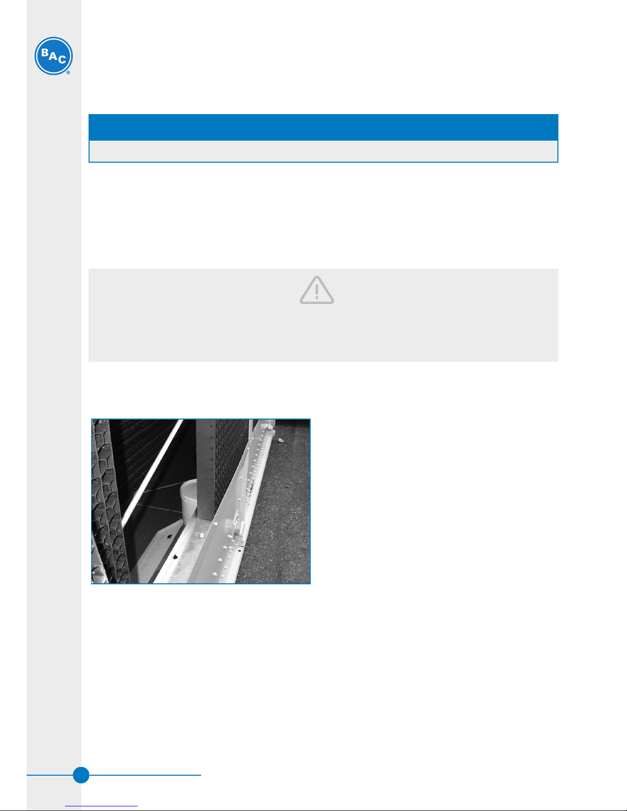
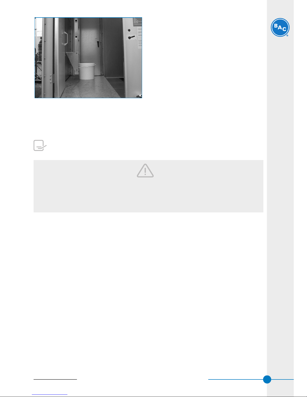
Bleed Line Installation
On all open cooling towers, install a bleed line with valve between the system circulating pump discharge riser and
a convenient drain. Locate the bleed line in a portion of the riser piping that drains when the pump is off.
The bleed valve should always be open when the unit is in operation, unless the bleed rate is automatically
controlled by a water treatment system.
Safety Precautions
All electrical, mechanical and rotating machinery constitutes a potential hazard, particularly for those not familiar
with its design, construction and operation. Accordingly, adequate safeguards (including use of protective
enclosures where necessary) should be taken with this equipment both to safeguard the public (including minors)
from injury and to prevent damage to the equipment, its associated system and the premises.
If there is doubt about safe and proper rigging, installation, operation or maintenance procedures, contact the
equipment manufacturer or his representative for advice.
When working on operating equipment, be aware that some parts may have an elevated temperature. Any
operations on elevated level have to be executed with extra care to prevent accidents.
AUTHORIZED PERSONNEL
The operation, maintenance and repair of this equipment should be undertaken only by personnel authorized and
qualified to do so. All such personnel should be thoroughly familiar with the equipment, the associated systems
and controls and the procedures set forth in this and other relevant manuals. Proper care, personal protective
equipment, procedures and tools must be used in handling, lifting, installing, operating, maintaining and repairing
this equipment to prevent personal injury and/or property damage. Personnel must use personal protective
equipment where necessary (gloves, ear plugs, etc...)
MECHANICAL SAFETY
Mechanical safety of the equipment is in accordance with the requirements of the EU machinery directive.
Depending upon site conditions it also may be necessary to install items such as bottom screens, ladders, safety
cages, stairways, access platforms, handrails and toe boards for the safety and convenience of the authorized
service and maintenance personnel.
At no time this equipment should be operated without all fan screens, access panels and access doors in place.
When the equipment is operated with a variable fan speed control device, steps must be taken to avoid operating
at or near to the fan's «critical speed».
For more information consult your local BAC Balticare representative.
W W W . B A L T I M O R E A I R C O I L . E U
8