8 — English
©2010 Baja, Inc. All Rights Reserved.
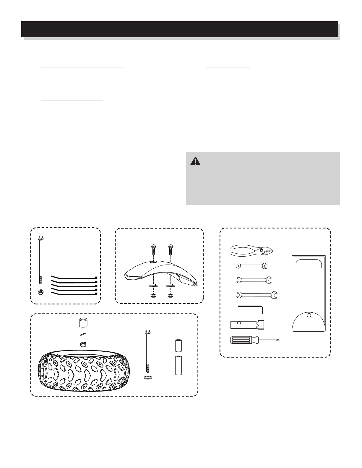
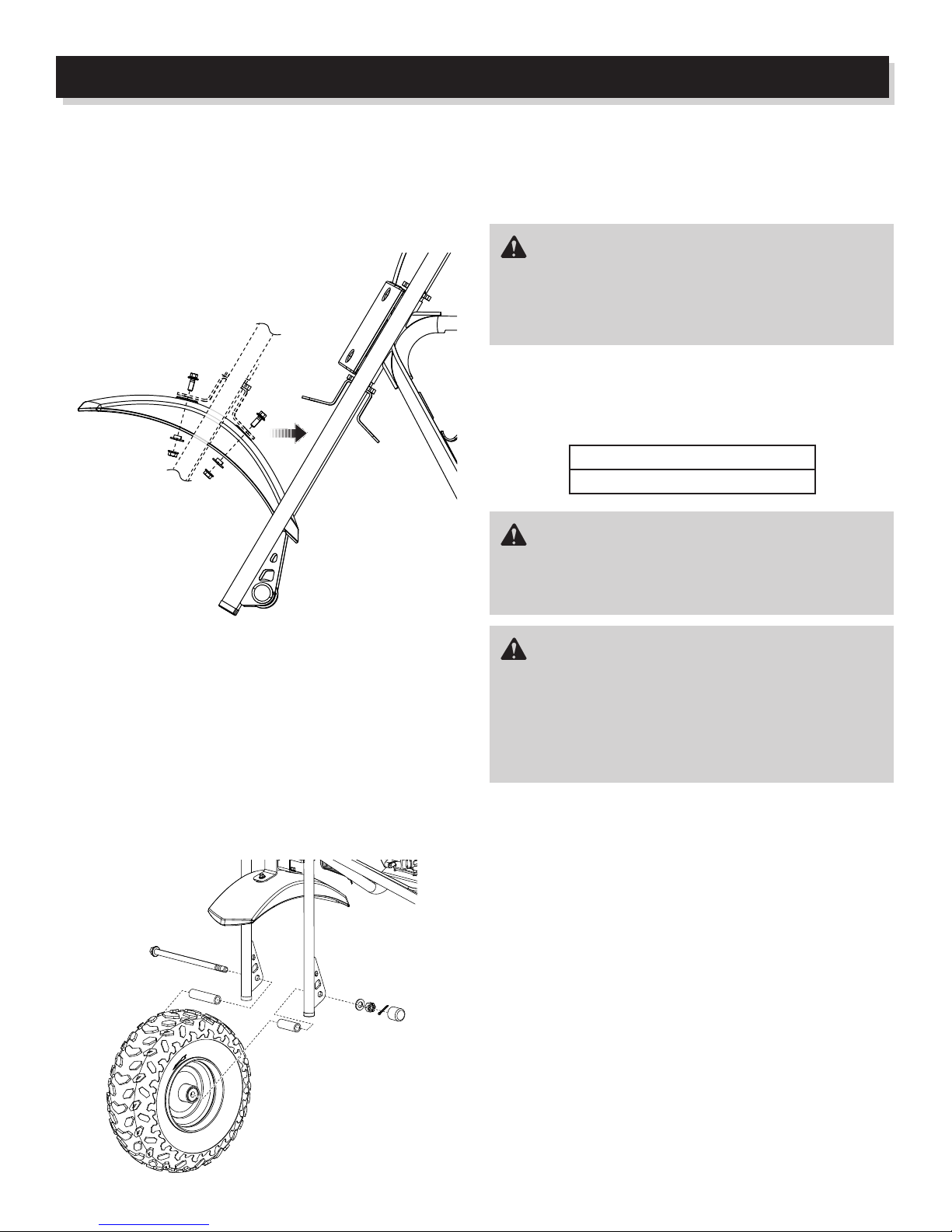
ASSEMBLY
CHECKING/CHANGING ENGINE LUBRICANT
Always use a 4-stroke motor lubricant that meets or exceeds
the requirements for API service classication SJ.
ENGINE
LUBRICANT
°C -30 -20 -10 0 10 20 30 40
TEMP.
°F -22 -4 14 32 50 68 86 104
To check lubricant level:
Park vehicle on level ground and lower side stand.
Start the engine and allow it to run for 3 to 5 minutes.
Turn the engine off and allow to cool for at least 3 minutes.
Unscrew the oil cap/dipstick and remove.
Wipe dipstick clean and re-seat in hole, but do not re-
thread.
Hold the mini bike upright, remove the dipstick, and inspect
the lubricant level. Level should be between the minimum
and maximum marks on the dipstick.
If lubricant is below minimum mark on dipstick, add lu-
bricant until level falls between minimum and maximum
marks on the dipstick.
To change engine lubricant:
Lubricant should be changed while the engine lubricant is still
warm, but not hot. This allows the lubricant to drain quickly
and completely.
Park vehicle on level ground and lower side stand.
Start the engine and allow it to run for 3 to 5 minutes.
Turn the engine off and allow to cool for at least 3 minutes.
Remove oil cap/dipstick.
Place a container underneath the oil drainage bolt to col-
lect used lubricant as it drains.
Unscrew the oil drainage bolt and remove the bolt and
washer.
Allow lubricant to drain completely.
Inspect sealing washer and replace if damaged.
NOTE: This should be replaced at least every other time
the lubricant is changed.
Reinstall washer and oil drainage bolt. Torque oil drainage
bolt to 18 ft.lbs. (24 Nm).
Fill crankcase with 0.40 qt. (0.45 l) of SAE15W40 lubricant.
Reinstall the oil cap/dipstick.
Start the engine and allow it to run for 3 to 5 minutes.
Turn the engine off and allow to cool for at least 3 minutes.
Hold the mini bike upright and recheck the lubricant level.
Make sure there are no leaks.
NOTE: Used lubricant should be disposed of at an approved
disposal site. See your local oil retailer for more information.
CAUTION:
Attempting to start the engine before it has been properly
lled with lubricant will result in equipment failure.
SAE 10W-30
SAE 20W-40
SAE 10W-50
SAE 15W-40