KTM 1290 Super Duke GT Series Manual

SETUP INSTRUCTIONS 2016
1290 Super Duke GT
Art. no. 3213506en


INTRODUCTION 1
*3213506en*
3213506en
03/2016
INTRODUCTION
The work described in these setup instructions must be performed before the vehicle is delivered to the customer.
Read the setup instructions in their entirety before beginning work.
These setup instructions were written to correspond to the latest state of this series. We reserve the right to make changes in the interest
of technical advancement without at the same time updating this manual.
We shall not provide a description of general workshop methods. Likewise, safety rules that apply in a workshop are not specified here. It
is assumed that the work will be performed by a fully trained mechanic.
All specifications are non-binding. KTM Sportmotorcycle GmbH specifically reserves the right to modify or delete technical specifications,
prices, colors, forms, materials, services, designs, equipment, etc., without prior notice and without specifying reasons, to adapt these to
local conditions, as well as to stop production of a particular model without prior notice. KTM accepts no liability for delivery options, devi-
ations from illustrations and descriptions, misprints, and other errors. The models portrayed partly contain special equipment that does not
belong to the regular scope of supply.
© 2016 KTM Sportmotorcycle GmbH, Mattighofen Austria
All rights reserved
Reproduction, even in part, as well as copying of all kinds, is permitted only with the express written permission of the copyright owner.
ISO 9001(12 100 6061)
According to the international quality management standard ISO 9001, KTM uses quality assurance processes that lead to
the maximum possible quality of the products.
Issued by: TÜV Management Service
KTM Sportmotorcycle GmbH
5230 Mattighofen, Austria
This document is valid for the following models:
1290 Super Duke GT EU (F9903P3, F9903PF)
1290 Super Duke GT AU (F9960P3, F9960PF)
1290 Super Duke GT JP (F9986P3, F9986PF)
1290 Super Duke GT US (F9975P3, F9975PF)

1 MEANS OF REPRESENTATION 2
1.1 Symbols used
The meaning of specific symbols is described below.
Indicates an expected reaction (e.g. of a work step or a function).
Indicates an unexpected reaction (e.g. of a work step or a function).
Indicates a page reference (more information is provided on the specified page).
Indicates information with more details or tips.
Indicates the result of a testing step.
Denotes a voltage measurement.
Denotes a current measurement.
Denotes a resistance measurement.
1.2 Formats used
The typographical formats used in this document are explained below.
Proprietary name Identifies a proprietary name.
Name®Identifies a protected name.
Brand™ Identifies a trademark.
Underlined terms Refer to technical details of the vehicle or indicate technical terms, which are explained
in the glossary.

2 SETUP 3
2.1 Unpacking and setting up the vehicle
Preparatory work
–Remove the box.
S01182-01
Main work
–Remove the adhesive tape in the upper area of the motorcycle.
S01183-01
–Roll down the film at the sides.
Info
To avoid damaging the motorcycle during unpacking, leave the other films
on the vehicle until you have finished work on the vehicle.
–Remove the separate enclosure and unpack it. Check the separate enclosure for
completeness.
–Check the vehicle for transport damage.
S01184-01
–Remove the controls from the transport holder. Remove the screws of the handlebar
clamp. Take off the handlebar clamp and transport holder.
S01185-10
–Remove right-hand handlebar weight .
–Position the controls on the right half of the handlebar but do not tighten yet.
E00283-10
Warning
Danger of accidents Handlebar breakage.
–If the handlebar is bent or straightened it will cause material fatigue,
and the handlebar can break. Always replace handlebar.
–Position the handlebar.
Info
Make sure the cables and wiring are positioned correctly.
–Position the handlebar clamp. Mount screws but do not tighten yet.
Marking on the handlebar scale is aligned with the top edge of the handle-
bar clamp.
Center line on the handlebar scale is aligned with the center of the handle-
bar clamp.
–First bolt the handlebar support with screws onto the longer, higher side of the
handlebar supports so that both parts touch.

2 SETUP 4
–Tighten screws evenly.
Guideline
Screw, handlebar clamp M8 20 Nm
(14.8 lbf ft)
S01186-10
–Tighten screws and of the controls.
Guideline
Remaining screws, chassis M6 10 Nm (7.4 lbf ft)
Screw, combination switch, right M5 3.5 Nm
(2.58 lbf ft)
–Mount right handlebar weight, tighten screw.
Guideline
Screw, handlebar weight M6 10 Nm (7.4 lbf ft)
–Check the throttle grip for smooth operation.
E00278-01
–Mount and tighten the rear mirror on both sides.
E00279-10
–Position windshield .
–Mount and tighten screws .
Guideline
Screw, windshield M5 3.5 Nm
(2.58 lbf ft)
E00277-01
–Tape on the protective plastic sheet for the swingarm.
–Remove the cable ties of the rider footrests.
E00281-10
–Mount splash protector with screws on license plate holder .
Guideline
Remaining screws, chassis EJOT PT®K50x12 1 Nm (0.7 lbf ft)

2 SETUP 5
E00282-10
(1290 Super Duke GT US)
–Bond the reflectors on the right and left side of the reflector holder.
–Mount the reflector holder on license plate holder .
Guideline
Remaining screws, chassis M6 10 Nm
(7.4 lbf ft)
E00273-01
–Remove the passenger seat. ( p. 7)
–Remove spare key and KEYCODECARD and keep in a safe place for the handover.
–Secure the tool set with the rubber holder.
E00274-01
–Carefully loosen and remove the tension belt from the frame.
Info
An assistant prevents the motorcycle from falling over.
–Carefully loosen and remove the tension belts around the fork legs.
The vehicle is released at the front.
–Together with an assistant, take the vehicle off the palette.
–Remove the radiator shield.
S01188-10
–Position the front spoiler. Mount and tighten screws with the washers.
Guideline
Remaining screws, chassis M6 10 Nm (7.4 lbf ft)
S01189-10
–Position metal sheets on the left and right. Mount and tighten screws .
Guideline
Remaining screws, chassis M5 5 Nm (3.7 lbf ft)
E00280-10
–Remove the front rider's seat. ( p. 7)
–Plug in the connector of starter relay .
(1290 Super Duke GT US)
–Mount the side cases.
Info
Observe the accompanying fitting instructions.
–Recharge the battery. ( p. 8)
–Remove the protective plastic.
–Refuel. ( p. 10)

2 SETUP 6
–Prepare the vehicle according to the specifications in the KTM Dealer.net for han-
dover to the customer.

3 WORK 7
3.1 Removing the passenger seat
S01106-10
–Insert the ignition key in seat lock and turn it clockwise.
–Raise front of the passenger seat, pull toward the tank, and remove upward.
–Remove the ignition key.
3.2 Mounting the passenger seat
402652-10
–Attach the hooks on the passenger seat to seat mounts .
–Lower the passenger seat and push back.
–Position locking pin in the lock housing and push down the passenger seat at
the front.
The locking pin engages with an audible click.
–Check that the passenger seat is correctly mounted.
3.3 Removing the front rider's seat
Preparatory work
–Remove the passenger seat. ( p. 7)
S01104-10
Main work
–Press seat release in the direction of the arrow and lift the front rider's seat at
the rear at the same time.
–Detach the front of the front rider's seat and remove it.
3.4 Mounting the front rider's seat
401921-10
Main work
–Attach recesses on the front rider's seat to the fuel tank, push the front rider's
seat forward.
–Position locking pin in the lock housing and push down the front rider's seat at
the rear.
The locking pin engages with an audible click.
–Check that the front rider's seat is correctly mounted.
Finishing work
–Mount the passenger seat. ( p. 7)

3 WORK 8
3.5 Recharging the battery
Warning
Risk of injury Battery acid and battery gases cause serious chemical burns.
–Keep batteries out of the reach of children.
–Wear suitable protective clothing and goggles.
–Avoid contact with battery acid and battery gases.
–Keep sparks and open flames away from the battery. Only charge in well-ventilated rooms.
–In the event of skin contact, rinse with large amounts of water. If battery acid gets in the eyes, rinse with water for at least
15 minutes and contact a physician.
Warning
Environmental hazard The battery contains elements that are harmful to the environment.
–Do not dispose of batteries with the household waste. Dispose of a defective battery in an environmentally friendly manner.
Give the battery to your authorized KTM dealer or dispose of it at a collection point for used batteries.
Warning
Environmental hazard Hazardous substances cause environmental damage.
–Oil, grease, filters, fuel, cleaners, brake fluid, etc., should be disposed of as stipulated in applicable regulations.
Info
Even when there is no load on the battery, it discharges steadily.
The charging level and the method of charging are very important for the service life of the battery.
Rapid recharging with a high charging current shortens the service life of the battery.
If the charging current, charging voltage, and charging time are exceeded, the battery will be destroyed.
If the battery is depleted from starting the vehicle repeatedly, the battery must be charged immediately.
If the battery is left in a discharged state for an extended period, it will become over-discharged and sulfated, destroying the
battery.
The battery is maintenance-free, i.e., the acid level does not have to be checked.
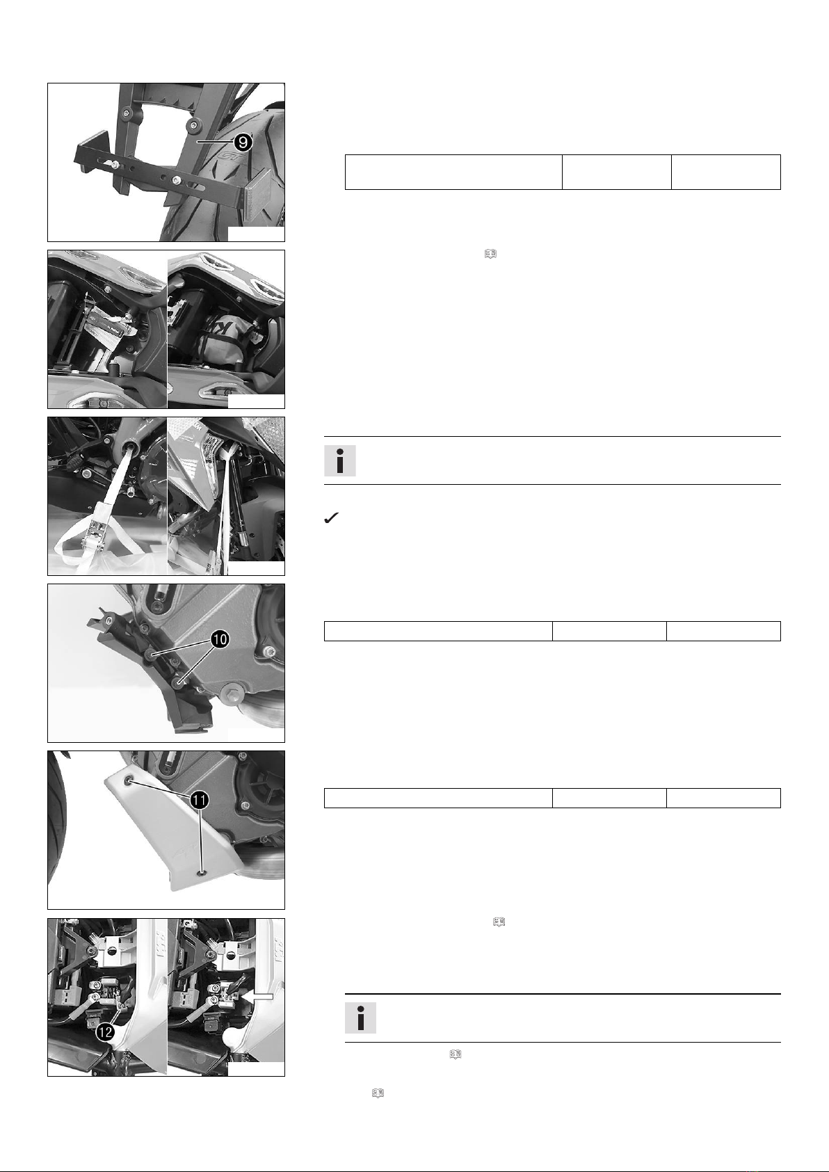
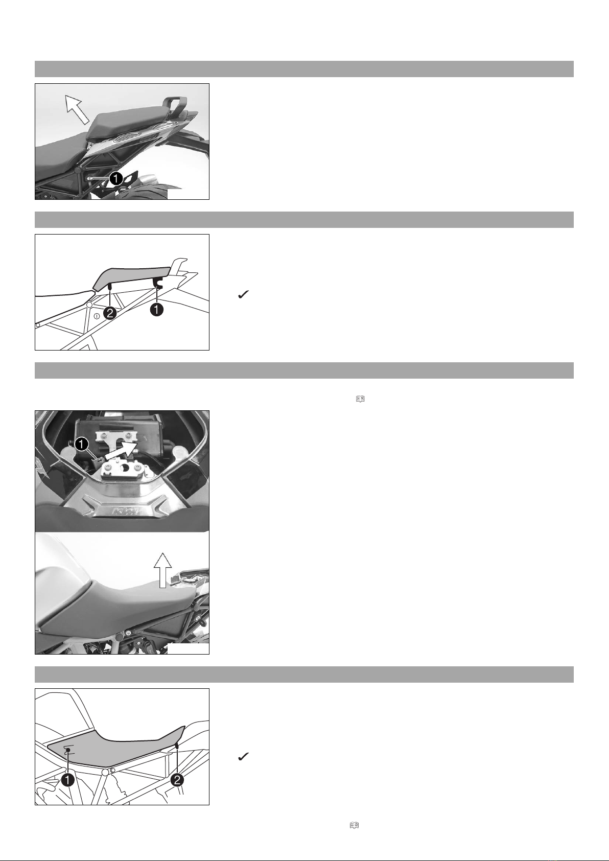
Preparatory work
–Switch off the ignition by turning the black ignition key to the position OFF .
–Remove the passenger seat. ( p. 7)
–Remove the front rider's seat. ( p. 7)
–Disconnect the negative cable of the battery. ( p. 9)
311910-10
Main work
–Connect the battery charger to the battery. Switch on the battery charger.
Battery charger XCharge-professional EU (00029095050)
Battery charger XCharge-professional US (00029095051)
Battery charger XCharge-professional GB (00029095052)
Battery charger XCharge-professional CH (00029095053)
Info
Follow the charger's instructions exactly.
–Switch off the battery charger after charging and disconnect from the battery.
Guideline
The charging current, charging voltage, and charging time must not be exceeded.
Charge the battery regularly when the
motorcycle is not in use
3 months
Finishing work
–Connect the negative cable of the battery. ( p. 9)
–Mount the front rider's seat. ( p. 7)
–Mount the passenger seat. ( p. 7)
–Set the time and date.

3 WORK 9
3.6 Disconnecting the negative cable of the battery
Warning
Risk of injury Battery acid and battery gases cause serious chemical burns.
–Keep batteries out of the reach of children.
–Wear suitable protective clothing and goggles.
–Avoid contact with battery acid and battery gases.
–Keep sparks and open flames away from the battery. Only charge in well-ventilated rooms.
–In the event of skin contact, rinse with large amounts of water. If battery acid gets in the eyes, rinse with water for at least
15 minutes and contact a physician.
Caution
Danger of accidents If the vehicle is operated with a discharged battery or without a battery, electronic components and safety
equipment may be damaged.
–Never operate the vehicle with a discharged battery or without a battery.
Preparatory work
–Switch off the ignition by turning the black ignition key to the position OFF .
–Remove the passenger seat. ( p. 7)
–Remove the front rider's seat. ( p. 7)
E00168-10
Main work
–Remove screw .
–Lift cover at the rear and pull toward the rear.
–Fold up the cover.
D01427-10
–Disconnect negative cable from the battery.
3.7 Connecting the negative cable of the battery
Warning
Risk of injury Battery acid and battery gases cause serious chemical burns.
–Keep batteries out of the reach of children.
–Wear suitable protective clothing and goggles.
–Avoid contact with battery acid and battery gases.
–Keep sparks and open flames away from the battery. Only charge in well-ventilated rooms.
–In the event of skin contact, rinse with large amounts of water. If battery acid gets in the eyes, rinse with water for at least
15 minutes and contact a physician.
Caution
Danger of accidents If the vehicle is operated with a discharged battery or without a battery, electronic components and safety
equipment may be damaged.
–Never operate the vehicle with a discharged battery or without a battery.

3 WORK 10
D01427-11
Main work
–Position negative cable ; mount and tighten the screw.
Guideline
Screw, battery terminal M6 4.5 Nm
(3.32 lbf ft)
D01428-10
–Fold down cover .
–Mount and tighten screw .
Guideline
Remaining screws, chassis M5 5 Nm (3.7 lbf ft)
Finishing work
–Mount the front rider's seat. ( p. 7)
–Mount the passenger seat. ( p. 7)
–Set the time and date.
3.8 Refueling
Danger
Fire hazard Fuel is highly flammable.
–Never refuel the vehicle near open flames or burning cigarettes, and always switch off the engine first. Be careful that no
fuel is spilt, especially on hot vehicle components. Clean up spilt fuel immediately.
–The fuel in the fuel tank expands when warm and may emerge if overfilled. Follow the instructions on refueling.
Warning
Danger of poisoning Fuel is poisonous and a health hazard.
–Fuel must not come into contact with the skin, eyes, or clothing. Do not breathe in the fuel vapors. If contact occurs with
the eyes, rinse with water immediately and contact a physician. Immediately clean contaminated areas on the skin with
soap and water. If fuel is swallowed, contact a physician immediately. Change clothing that is contaminated with fuel.
Note
Material damage Premature clogging of the fuel filter.
–In some countries and regions, the available fuel quality and cleanliness may not be sufficient. This will result in problems with
the fuel system.
–Only refuel with clean fuel that meets the specified standards.
Warning
Environmental hazard Improper handling of fuel is a danger to the environment.
–Do not allow fuel to get into the ground water, the ground, or the sewage system.
H01291-10
–Switch off the engine.
–Open the filler cap. ( p. 11)
–Fill the fuel tank with fuel up to the lower edge of the filler neck.
Total fuel tank
capacity, approx.
23 l (6.1 US gal) Super unleaded (ROZ 95/RON 95/PON
91) ( p. 16)
–Close the filler cap. ( p. 11)

3 WORK 11
3.9 Opening the filler cap
Danger
Fire hazard Fuel is highly flammable.
–Never refuel the vehicle near open flames or burning cigarettes, and always switch off the engine first. Be careful that no
fuel is spilt, especially on hot vehicle components. Clean up spilt fuel immediately.
–The fuel in the fuel tank expands when warm and may emerge if overfilled. Follow the instructions on refueling.
Warning
Danger of poisoning Fuel is poisonous and a health hazard.
–Fuel must not come into contact with the skin, eyes, or clothing. Do not breathe in the fuel vapors. If contact occurs with
the eyes, rinse with water immediately and contact a physician. Immediately clean contaminated areas on the skin with
soap and water. If fuel is swallowed, contact a physician immediately. Change clothing that has been contaminated with
fuel. Store fuel properly in a suitable canister and keep away from children.
Warning
Environmental hazard Improper handling of fuel is a danger to the environment.
–Do not allow fuel to get into the ground water, the ground, or the sewage system.
H01281-10
–Lift cover of the filler cap and insert ignition key in the fuel tank lock.
H01282-10
Note
Danger of damage Ignition key breakage.
–To take pressure off of the ignition key, push down on the filler cap. Damaged
ignition keys must be replaced.
–Turn ignition key clockwise.
–Fold open filler cap .
3.10 Closing the filler cap
H01283-10
–Fold down filler cap .
–Turn ignition key clockwise.
H01284-10
–Press down the filler cap and turn back ignition key until the fuel tank lock
locks.
Warning
Fire hazard Fuel is highly flammable, poisonous and harmful to your
health.
–After closing the filler cap, ensure that it is locked properly. Change
clothing that has been contaminated with fuel. Immediately clean con-
taminated areas on the skin with soap and water.

3 WORK 12
–Remove ignition key and close cover .
3.11 "Clock/Date"
401990-02
Condition
• The vehicle is stationary.
–Press the UP or DOWN button until the "Settings" menu appears on the matrix dis-
play. Pressing the SET button opens the menu.
–Press the UP or DOWN button until "Clock/Date" is highlighted in black on the matrix
display. Pressing the SET button again opens the menu.
–Use the UP or DOWN button to navigate through the menu. Use the SET button to
set the time and date.
If the battery was disconnected from the vehicle, the time and date must be set in the
matrix display.

4 TECHNICAL DATA 13
4.1 Chassis tightening torques
Remaining screws, chassis EJOT PT®K50x12 1 Nm (0.7 lbf ft) –
Remaining screws, chassis EJOT PT®K50x14 1 Nm (0.7 lbf ft) –
Remaining screws, chassis EJOT PT®K50x16 2 Nm (1.5 lbf ft) –
Remaining screws, chassis EJOT PT®K50x18 2 Nm (1.5 lbf ft) –
Screw, air filter box lid EJOT PT®K60 2 Nm (1.5 lbf ft) –
Screw, tail light EJOT PT®K50x14 2.5 Nm (1.84 lbf ft) –
Screw, combination switch, left M4 2.5 Nm (1.84 lbf ft) –
Screw, side stand switch M4 2 Nm (1.5 lbf ft) –
Remaining nuts, chassis M5 5 Nm (3.7 lbf ft) –
Remaining screws, chassis M5 5 Nm (3.7 lbf ft) –
Screw, cable channel M5 5 Nm (3.7 lbf ft) –
Screw, chain sliding guard M5 5 Nm (3.7 lbf ft) –
Screw, combination switch, right M5 3.5 Nm (2.58 lbf ft) –
Screw, cornering light M5 2 Nm (1.5 lbf ft) –
Screw, cover part M5 5 Nm (3.7 lbf ft) –
Screw, filler cap M5 3 Nm (2.2 lbf ft) –
Screw, fuel level indicator M5 3 Nm (2.2 lbf ft) –
Screw, shock absorber adjusting ring M5 5 Nm (3.7 lbf ft) –
Ground fitting on frame M6 10 Nm (7.4 lbf ft) –
Nut throttle cable valve control M6 5 Nm (3.7 lbf ft) –
Nut, ABS unit attachment M6 5 Nm (3.7 lbf ft) –
Nut, cable on starter motor M6 4 Nm (3 lbf ft) –
Remaining nuts, chassis M6 10 Nm (7.4 lbf ft) –
Remaining screws, chassis M6 10 Nm (7.4 lbf ft) –
Screw, ball joint of push rod on foot
brake cylinder
M6 5 Nm (3.7 lbf ft) Loctite®243™
Screw, battery terminal M6 4.5 Nm (3.32 lbf ft) –
Screw, clutch assembly M6 5 Nm (3.7 lbf ft) Loctite®243™
Screw, connecting piece, rear brake
line
M6 10 Nm (7.4 lbf ft) Loctite®243™
Screw, cooler retaining bracket M6 7 Nm (5.2 lbf ft) –
Screw, exhaust clamp on main silencer M6 8 Nm (5.9 lbf ft) –
Screw, exhaust clamp on manifold M6 8 Nm (5.9 lbf ft) –
Screw, foot brake cylinder M6 10 Nm (7.4 lbf ft) Loctite®243™
Screw, fuel pump M6 6 Nm (4.4 lbf ft) –
Screw, handlebar weight M6 10 Nm (7.4 lbf ft) –
Screw, license plate holder on lower
rear panel
M6 12 Nm (8.9 lbf ft) –
Screw, radiator hose clamp M6 3 Nm (2.2 lbf ft) –
Screw, sensor box M6 6 Nm (4.4 lbf ft) Loctite®243™
Screw, shift lever stub M6 10 Nm (7.4 lbf ft) Loctite®243™
Screw, shift rod M6 5 Nm (3.7 lbf ft) Loctite®243™
Screw, shift shaft deflector on shift
shaft
M6 18 Nm (13.3 lbf ft) Loctite®243™
Screw, side stand stub M6 6 Nm (4.4 lbf ft) Loctite®243™
Screw, steering damper, holder, on
frame
M6 8 Nm (5.9 lbf ft) Loctite®243™
Screw, step plate for foot brake lever M6 10 Nm (7.4 lbf ft) Loctite®243™
Screw, tire pressure sensor
(1290 Super Duke GT EU,
1290 Super Duke GT AU,
1290 Super Duke GT US)
M6 7 Nm (5.2 lbf ft) –
Screw, wheel speed sensor, front M6 4 Nm (3 lbf ft) –

4 TECHNICAL DATA 14
Screw, wheel speed sensor, rear M6 4 Nm (3 lbf ft) –
Nut, manifold on cylinder head M8 Tightening sequence:
Tighten the nuts evenly. Do
not warp the metal plate.
25 Nm (18.4 lbf ft)
–
Nut, rear sprocket M8 36 Nm (26.6 lbf ft) –
Nut, shift rod M8 12 Nm (8.9 lbf ft) –
Nut, shift rod M8LH 12 Nm (8.9 lbf ft) –
Nut, valve, angled
(1290 Super Duke GT JP)
M8 4 Nm (3 lbf ft) –
Nut, valve, angled
(1290 Super Duke GT EU,
1290 Super Duke GT AU,
1290 Super Duke GT US)
M8 6 Nm (4.4 lbf ft) –
Remaining nuts, chassis M8 25 Nm (18.4 lbf ft) –
Remaining screws, chassis M8 25 Nm (18.4 lbf ft) –
Screw, axle clamp M8 15 Nm (11.1 lbf ft) –
Screw, bottom triple clamp M8 15 Nm (11.1 lbf ft) –
Screw, foot brake lever M8 20 Nm (14.8 lbf ft) Loctite®243™
Screw, front brake disc M8 30 Nm (22.1 lbf ft) Loctite®2701™
Screw, front rider footrest bracket M8 25 Nm (18.4 lbf ft) Loctite®243™
Screw, handlebar clamp M8 20 Nm (14.8 lbf ft) –
Screw, ignition lock (tamper-proof
screw)
M8 25 Nm (18.4 lbf ft) –
Screw, rear brake caliper M8 25 Nm (18.4 lbf ft) Loctite®2701™
Screw, rear brake disc M8 30 Nm (22.1 lbf ft) Loctite®243™
Screw, shift lever on footrest bracket M8 20 Nm (14.8 lbf ft) Loctite®243™
Screw, shift shaft deflector on frame M8 10 Nm (7.4 lbf ft) Loctite®243™
Screw, side stand bracket M8 25 Nm (18.4 lbf ft) Loctite®243™
Screw, side stand spring M8 15 Nm (11.1 lbf ft) Loctite®2701™
Screw, steering damper on holder M8 8 Nm (5.9 lbf ft) Loctite®243™
Screw, steering damper on triple clamp M8 8 Nm (5.9 lbf ft) Loctite®243™
Screw, steering stem clamp M8 20 Nm (14.8 lbf ft) Loctite®243™
Screw, top triple clamp M8 18 Nm (13.3 lbf ft) –
Remaining nuts, chassis M10 45 Nm (33.2 lbf ft) –
Remaining screws, chassis M10 45 Nm (33.2 lbf ft) –
Screw, engine bearer M10 45 Nm (33.2 lbf ft) Loctite®243™
Screw, front brake caliper M10 45 Nm (33.2 lbf ft) Loctite®243™
Screw, handlebar support M10 40 Nm (29.5 lbf ft) Loctite®243™
Screw, side stand M10 35 Nm (25.8 lbf ft) Loctite®243™
Screw, side stand bracket M10 45 Nm (33.2 lbf ft) Loctite®243™
Screw, side stand retaining plate M10 45 Nm (33.2 lbf ft) Loctite®243™
Banjo bolt, brake line M10x1 25 Nm (18.4 lbf ft) –
Banjo bolt, brake line, connecting
piece, rear
M10x1 15 Nm (11.1 lbf ft) –
Nut, rear hub shock absorber carrier M10x1.25 45 Nm (33.2 lbf ft) Loctite®243™
Lambda sensor M12x1.25 25 Nm (18.4 lbf ft) –
Screw, bottom shock absorber M14x1.5 80 Nm (59 lbf ft) Thread greased
Screw, top shock absorber M14x1.5 80 Nm (59 lbf ft) Thread greased
Screw, eccentric M16 70 Nm (51.6 lbf ft) –
Nut, swingarm pivot M19x1.5 130 Nm (95.9 lbf ft) Thread greased
Nut, seat lock M22x1.5 6 Nm (4.4 lbf ft) –
Bolt, front axle M25x1.5 45 Nm (33.2 lbf ft) Thread greased
Screw, steering head, top M25x1.5 18 Nm (13.3 lbf ft) –

4 TECHNICAL DATA 15
Nut, rear axle, shock absorber side M35x1.5 200 Nm (147.5 lbf ft) Loctite®262™/lock the lock-
ing wire with locking varnish
Nut, rear axle M50x1.5 250 Nm (184.4 lbf ft) Thread greased/lock locking
wire with locking varnish

5 SUBSTANCES 16
Super unleaded (ROZ 95/RON 95/PON 91)
Standard/classification
–DIN EN 228 (ROZ 95/RON 95/PON 91)
Guideline
–Only use unleaded super fuel that matches or is equivalent to the specified fuel grade.
–Fuel with an ethanol content of up to 10 % (E10 fuel) is safe to use.
Info
Do not use fuel containing methanol (e. g. M15, M85, M100) or more than 10 % ethanol (e. g. E15, E25, E85, E100).

*3213506en*
3213506en
03/2016
KTM Sportmotorcycle GmbH
5230 Mattighofen/Austria
http://www.ktm.com
Photo: Mitterbauer/KTM
This manual suits for next models
12
Other KTM Motorcycle manuals

KTM
KTM 50 SX PRO SENIOR LC User manual

KTM
KTM 390 Duke EU User manual

KTM
KTM 990 Adventure EU 2009 User manual

KTM
KTM RC 390 2018 User manual

KTM
KTM 950 R User manual

KTM
KTM 950 SUPERMOTO 2007 User manual

KTM
KTM ADVENTURE R 640 Guide

KTM
KTM 250 SX-F User manual

KTM
KTM 150 EXC TPI 2021 Manual

KTM
KTM 2011 690 SMC EU Operating instructions

KTM
KTM 250 XC EU 2010 Manual

KTM
KTM 350 EXC-F 2023 User manual

KTM
KTM 450 XC-F User manual

KTM
KTM 250 SX 2022 User manual

KTM
KTM RC 125 Manual

KTM
KTM 2015 RC 390 EU User manual

KTM
KTM 350 SX-F Cairoli replica User manual

KTM
KTM 200 Duke US 2020 User manual

KTM
KTM 690 Duke EU 2014 Manual

KTM
KTM 2015 125 SX EU Manual