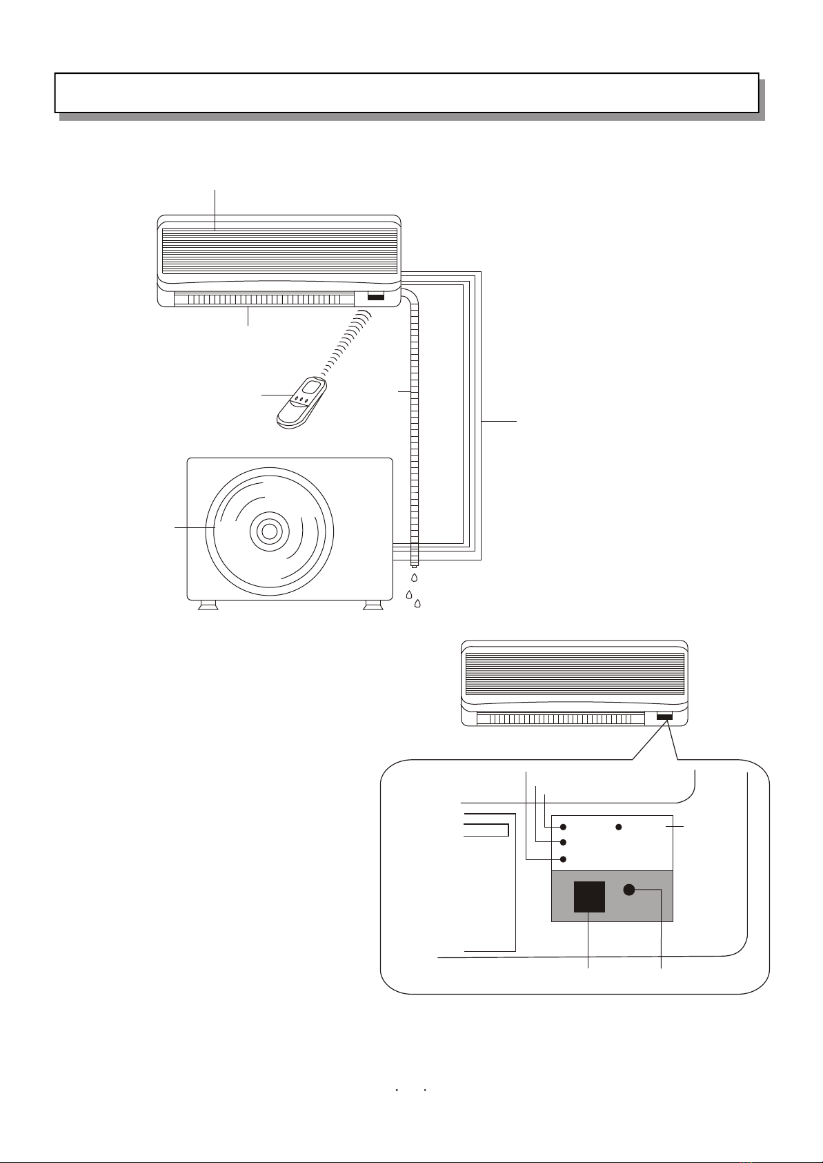
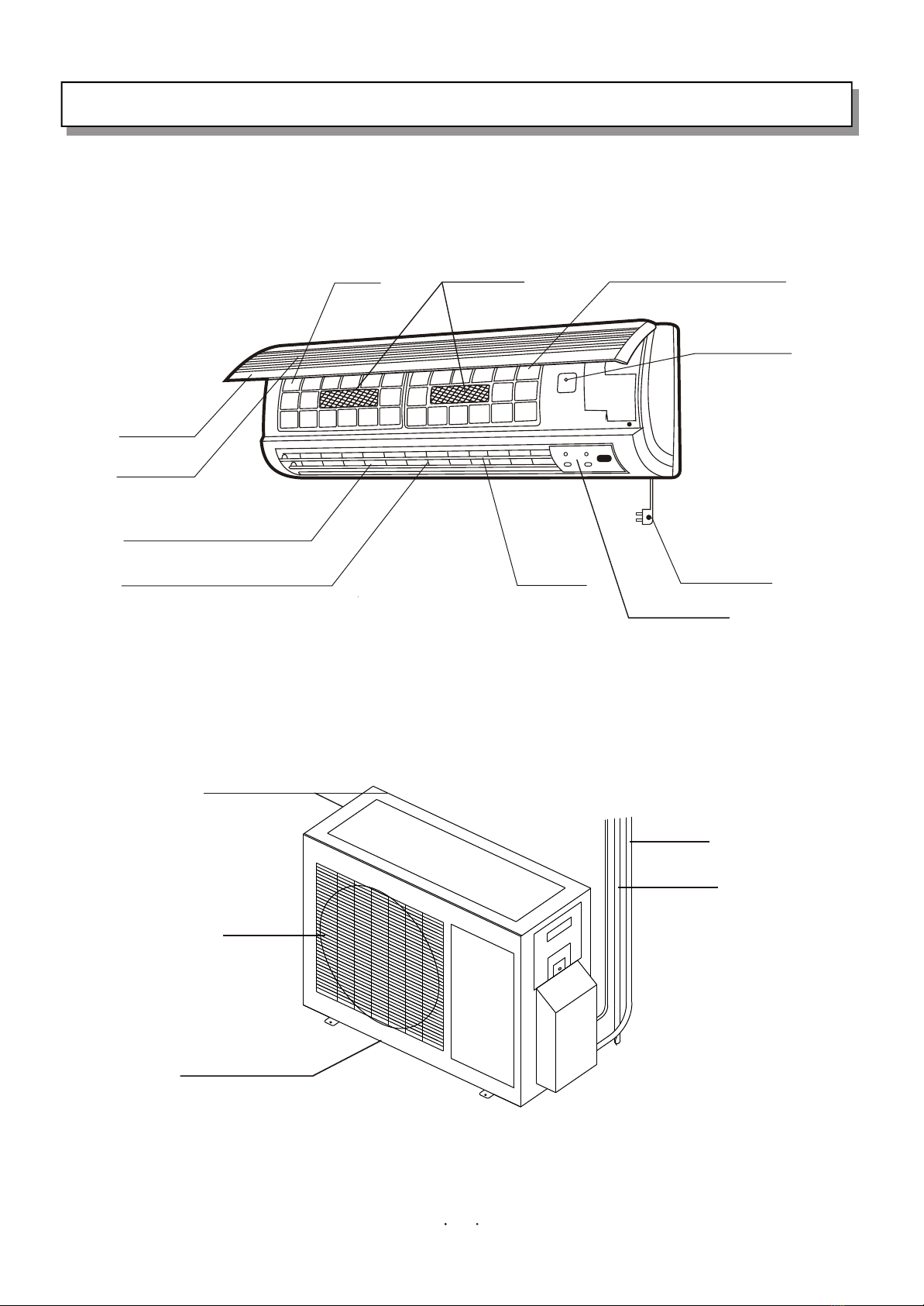
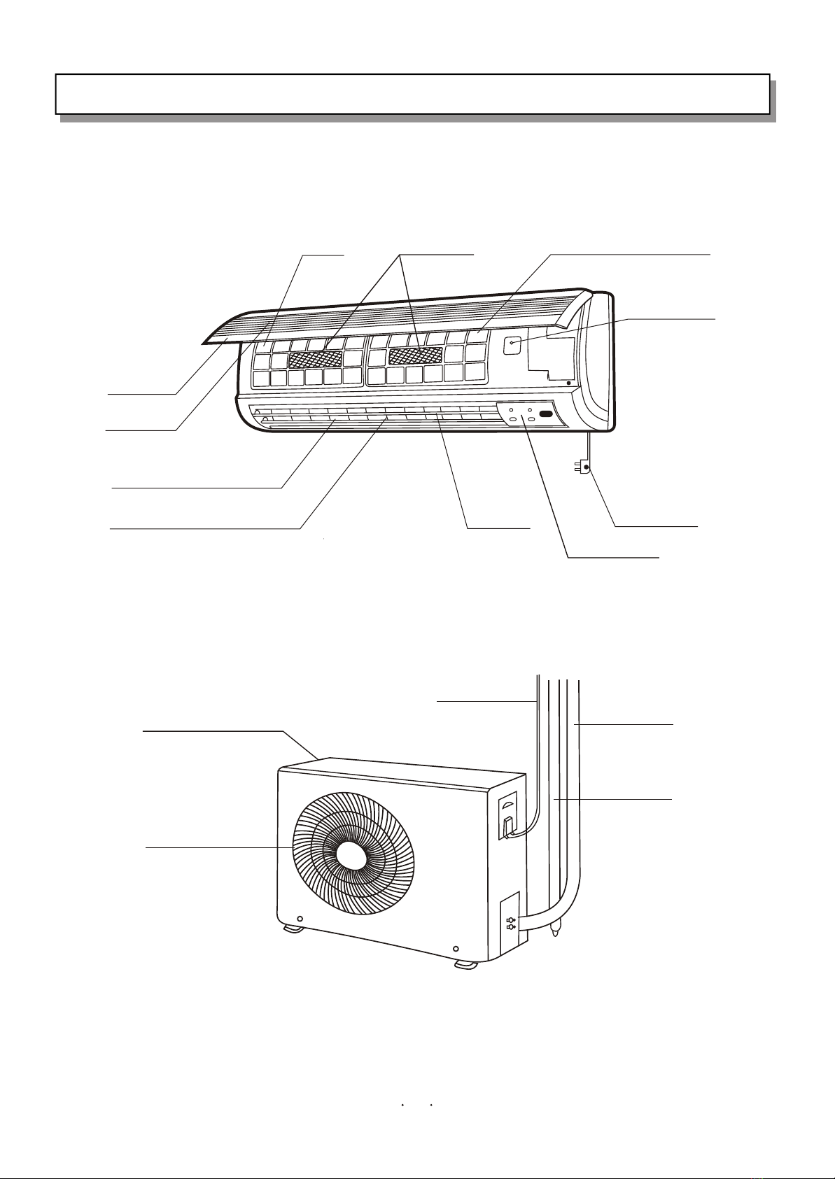
1. PART NAMES AND FUNCTIONS
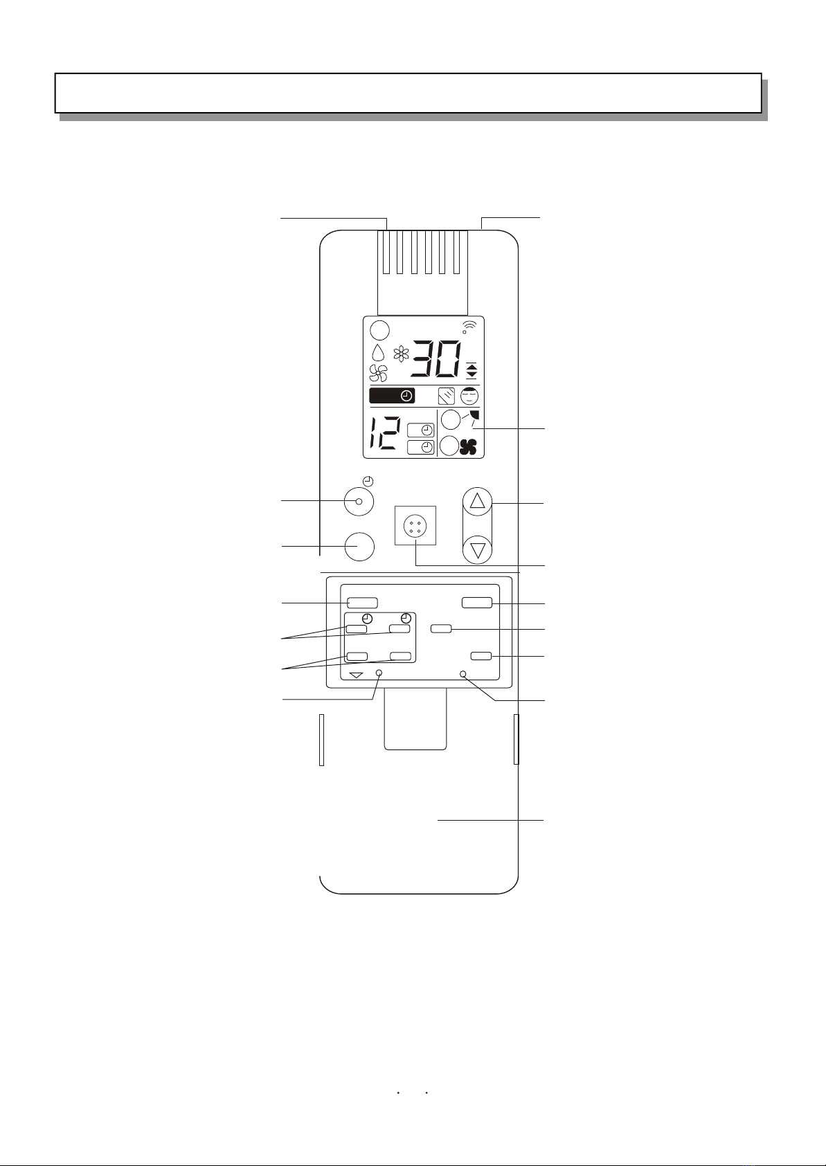
KF-5002GWE REMOTE CONTROL UNIT
AA
T.SETTINGT.SETTING
C
A
A
HOUR
ON
OFF
H.P. ON/OFF TEMP.
SLEEP
FLAP
ON OFF
SET CLR
SENSOR
BATTERY
FAN/MUTE
RESET
MODE
Sensor
Testing the ambient temperature
of the remote control unit
LCD
Displaying the running condition.
Hi-power running button
Sleep button
Press the button, the appliance enter
sleep mode.
Flap
Up-down adjustment
Timer on/off button
Setting the time of appliance on/off.
Set/cancel timer button
Set or cancel the time of appliance
on/off.
A/C sensor button
Press the button if the remote control
unit is liable to be affected by the heat
resource, such as electric blanket,
radiator or sunlight, this will use the
sensor of indoor unit, the symbol will
appear on the LCD.
Transmitter
Transmitting signals to the indoor unit,
the symbol will appear on the top of
LCD.
On/Off button
Press the button to run, press again
to cease.
Temperature setting button
Press the button marked " "or
" " to increase or decrease
the temperature.
Mode selection button
Auto dehumidification
Fan cooling
Fan speed selection button
Reset button
Press the button after batteries are
loaded and indication appears on
LCD.
Sliding cover
Battery compartment
Remove the batteries in the remote control unit when it is not used for a long period.
Replace the batteries when the indication on the LCD of the remote control unit is faint, or the remote control unit cannot be
set or operated.
Properly dispose of used batteries.
Keep the remote control unit away from cold or hot air, sunlight or heat sources.
Contact the local distributor if the receiver in the appliance does not work in a room illuminated by fluorescent tubes.
Remote control unit must be used within its effective range or the timer and the temperature control will not function properly.
Control will fail if two of the same model appliances are installed in the same room.
If the remote control unit is fixed on the wall, press the On/Off button to ensure that the appliance is receiving a signal from the
device.
COMMONSENSE
7