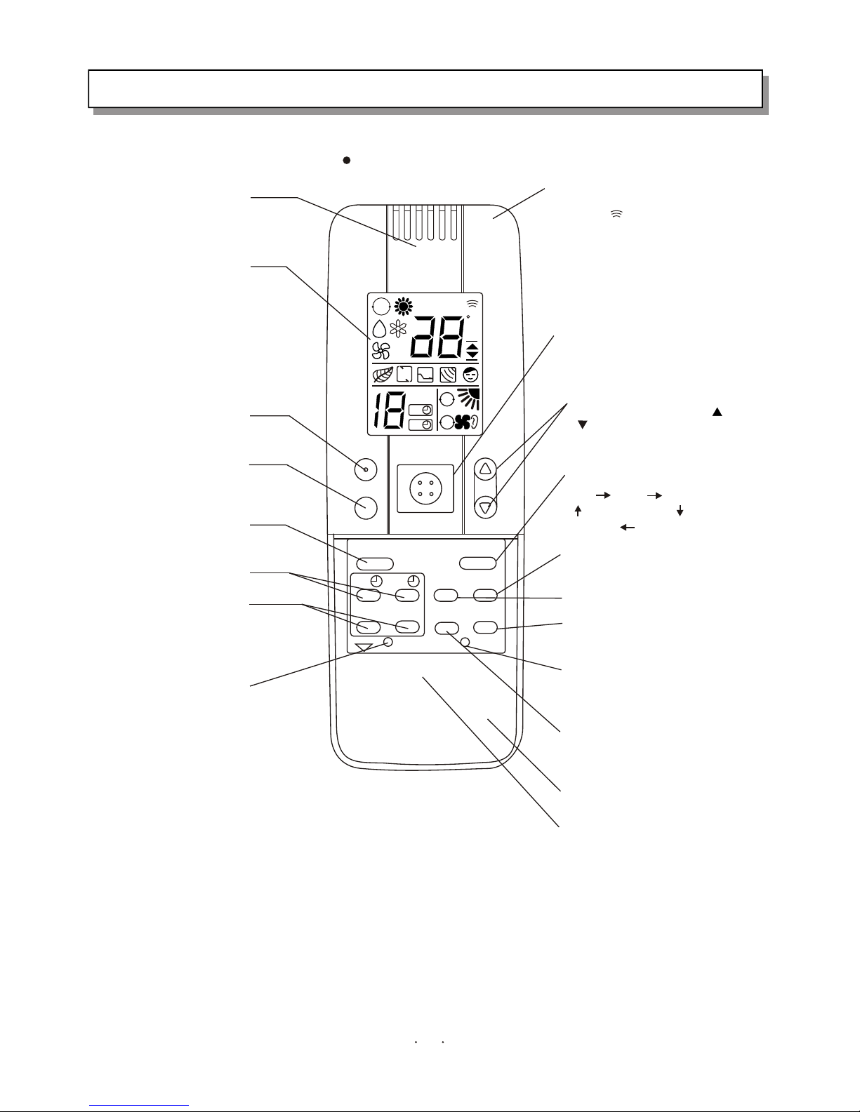
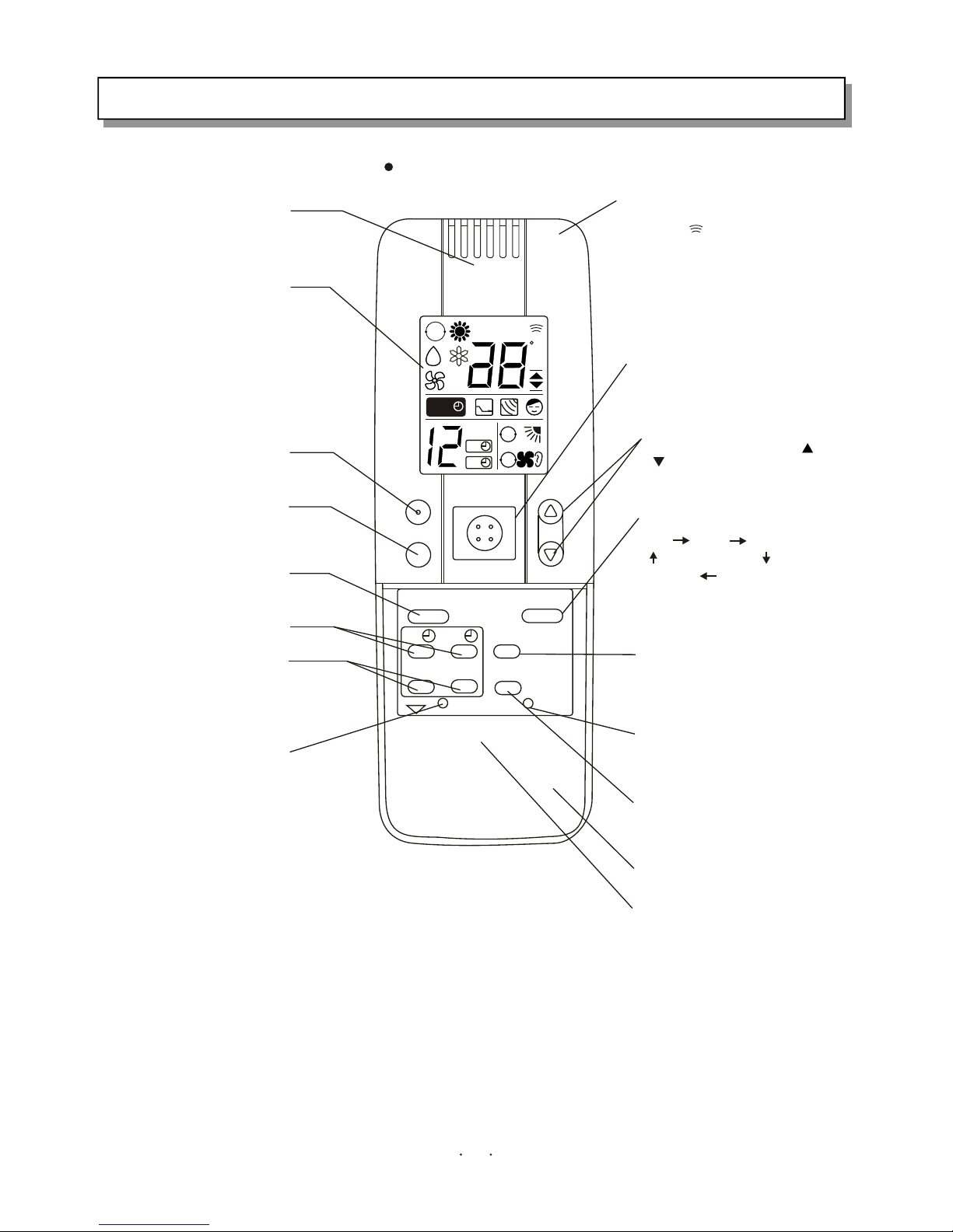
REMOTE CONTROL UNIT
1Сʱ
AA
T.SETTINGT.SETTING
C
A
A
A
HOUR
ON
OFF
H.P. ON/OFF TEMP.
SLEEP
FLAP
ON OFF
SET CLR
SENSOR
BATTERY
FAN/MUTE
SOFT
RESET
TEMP.DISP
ATR EX.
MODE
Sensor
Testing the ambient temperature
of the remote control unit
LCD
Displaying the running condition.
Hi-power running button
Sleep button
Press the button, the appliance enter
sleep mode.
Flap
Up-down adjustment
Timer on/off button
Setting the time of appliance on/off.
Set/cancel timer button
Set or cancel the time of appliance
on/off.
A/C sensor button
Press the button if the remote
control unit is liable to be affected by
the heat resource, such as electric
blanket, radiator or sunlight, this will
use the sensor of indoor unit, the
symbol will appear on the LCD.
Transmitter
Transmitting signals to the indoor unit,
the symbol will appear on the top of
LCD.
On/Off button
Press the button to run, press again
to cease.
Temperature setting button
Press the button marked " "or
the temperature.
Air exchange button
When this function works, the air
can be keep fresh.
Mode selection button
Auto heating dehumidification
Fan cooling
Fan speed selection button
Temperature displaying button
setting the temperature in the screen
of indoor unit
Reset button
Press the button after batteries are
loaded and indication appears on
LCD.
Duel energy-saving
This function can be used for
Restricting the max. electric current
by control software.
Sliding cover
Battery compartment
" " to increase or decrease
3
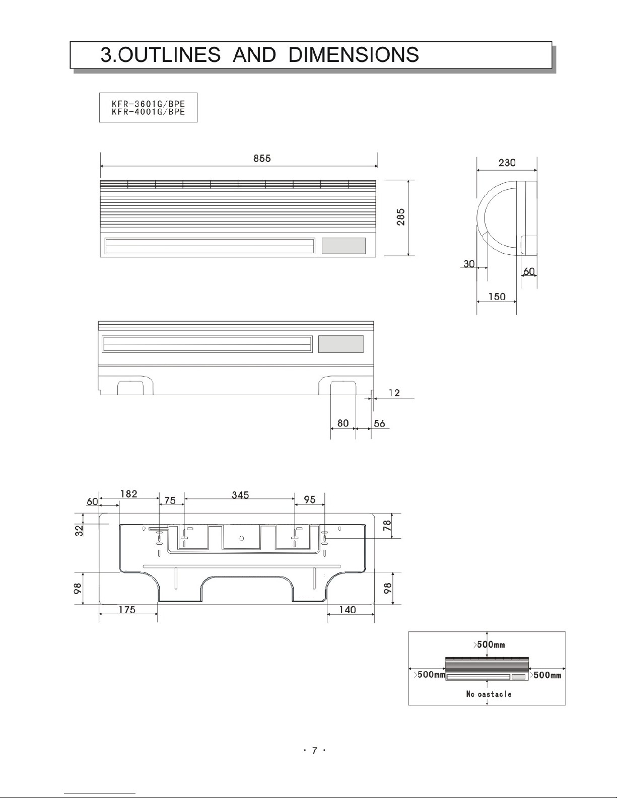
KFR-3601G/BPE
KFR-4001 /BPEG
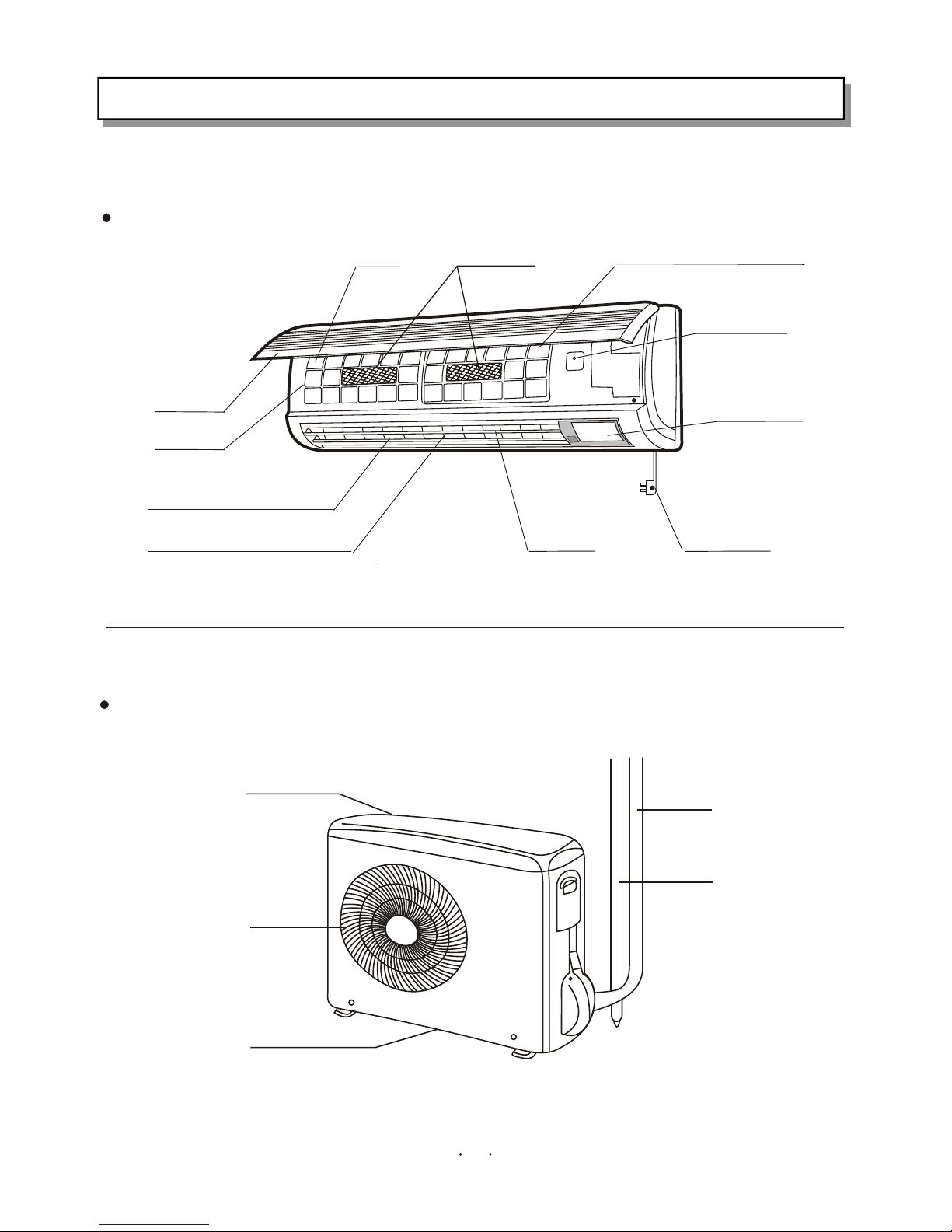
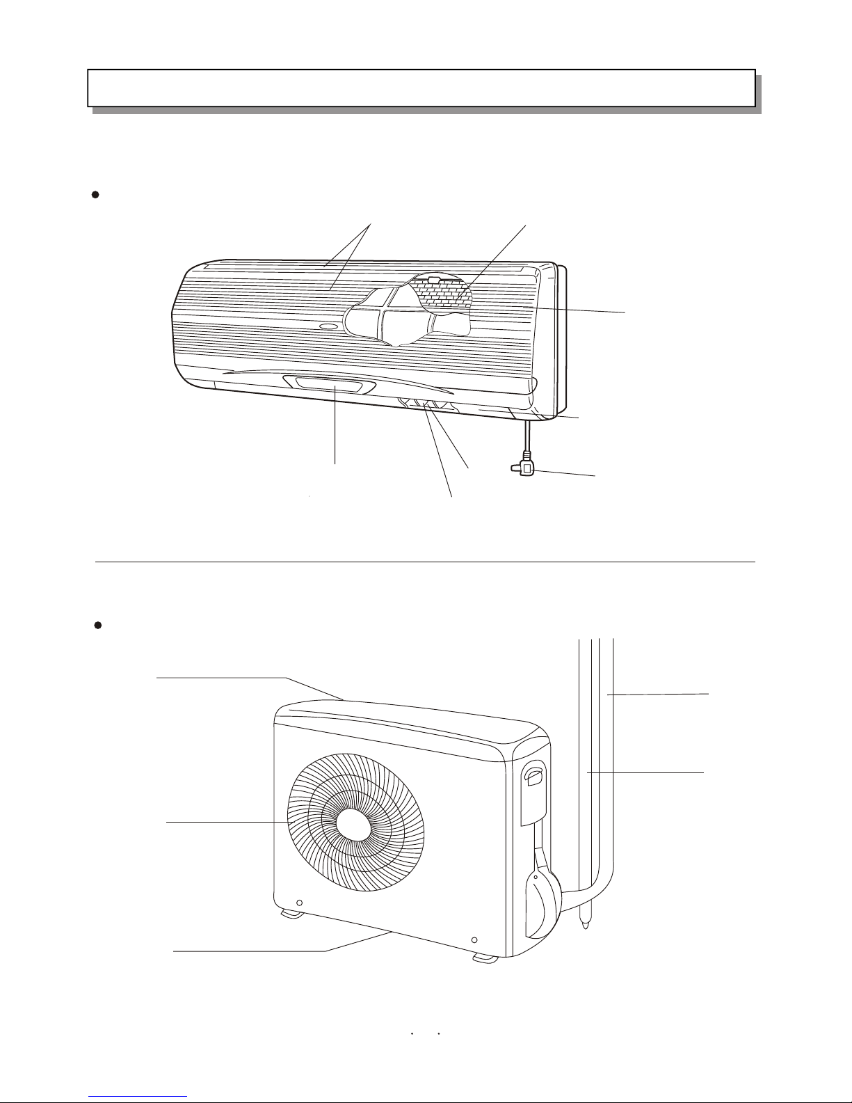
1. PART NAMES AND FUNCTIONS
REMARK: The remote controller transmits signal to indoor unit at 3 minutes intervals. If the indoor unit
has not received the signal for more than 10 minutes due to remote controller missing or other reason,
the sensor on indoor unit will be used for detecting indoor temperature automatically. Here, ambient
temperature of remote controller is likely to slightly different from that detecting by the indoor unit,
temperature will be compensated automatically. When the remote controller is missing or the batteries
are exhausted, please use the temporary switch.