Bamo EVEREST 214-S User manual

EVEREST 214-S
4 limit value relays
USER MANUAL
RE
10-02-2022 M-232.04-EN-AB 232-04/1
4 limit value relays
EVEREST 214-S
22, Rue de la Voie des Bans · Z.I. de la gare · 95100 ARGENTEUIL
Tel
Fax
+33 (0)1 30 25 83 20
+33 (0)1 34 10 16 05
Web
E-mail
www.bamo.eu
INTERNATIONAL

SUMMARY
3SAFETY INSTRUCTIONS
3DESCRIPTION
3TECHNICAL FEATURES
3MAINTENANCE
4OPERATING THE EVEREST 214S
4CONTROLS
4LIMIT RELAY 1 to 4
4LIMIT VALUE
4DELAY
5HYSTERESIS
5NC or NO SELECTION
5ASSIGNING OUTPUT RELAY TO INPUT E1 OR E2
5OVER-RANGING DISPLAY
5CLOCK-TIMER
6SCALING INPUT 1 AND 2
6FILTER (DAMPER)
6HOLD FUNCTION
6RESET TO FACTORY DEFAULT SETTINGS
7OPERATING MENU
8ELECTRICAL CONNECTIONS
RE
10-02-2022 M-232.04-EN-AB 232-04/2
4 limit value relays
EVEREST 214-S
22, Rue de la Voie des Bans · Z.I. de la gare · 95100 ARGENTEUIL
Tel
Fax
+33 (0)1 30 25 83 20
+33 (0)1 34 10 16 05
Web
E-mail
www.bamo.eu
INTERNATIONAL

SAFETY INSTRUCTIONS
- Installation, commissioning and maintenance may only be carried out by specialist personnel.
- Only connect the device to the voltage specified in the technical data or on the type label.
- The device must be disconnected from all sources of power during installation and maintenance work.
- The device may only be operated under the conditions specified in the operating instructions.
DESCRIPTION
The two-channel measuring amplifier EVEREST 214S is a processor-controlled display device for DIN rail installation. It has a built-in timer
and can supply sensors with 24V DC voltage. It converts 2 analogue signals into limit values. Freely scalable inputs and relays allow a wide
field of applications.
TECHNICAL FEATURES
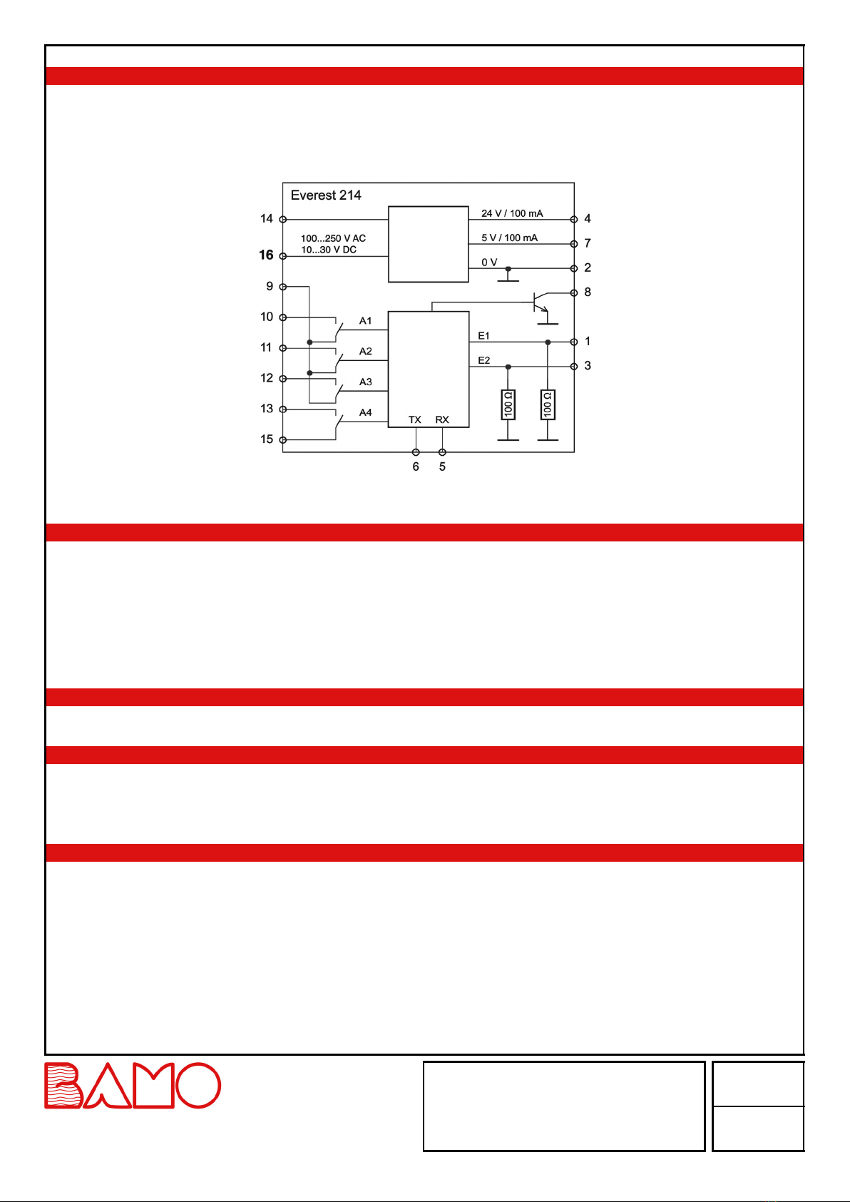
Power supply 100 ... 240 V AC - 50/60 Hz
10 ... 30 V DC and 12 ... 24 V AC
Consumption 1 ... 5 W
Measurement inputs 2 Channels 4 ... 20 mA (factory setting) scalable from 0 to 25 mA
Supply to sensors 24 V DC, Max. 100 mA and 5 V DC, Max. 100mA
Measurement accuracy 0.5 % ± 0.5 Digit
Measurement filter Adjustable from 0.1 to 9.9 s
Reset hysteresis Adjustable from 1 to 99 %
Limit contacts 250 V AC, 2A / 30 V DC, 1A
Note:
The contacts are not protected against overload. Provide an external protective device.
Output relays S1, S2, S3 3 potential free contacts, common shared
Open / Close function settings
Output relay S4 Open / close settings or timer function from 1 s to 24 h
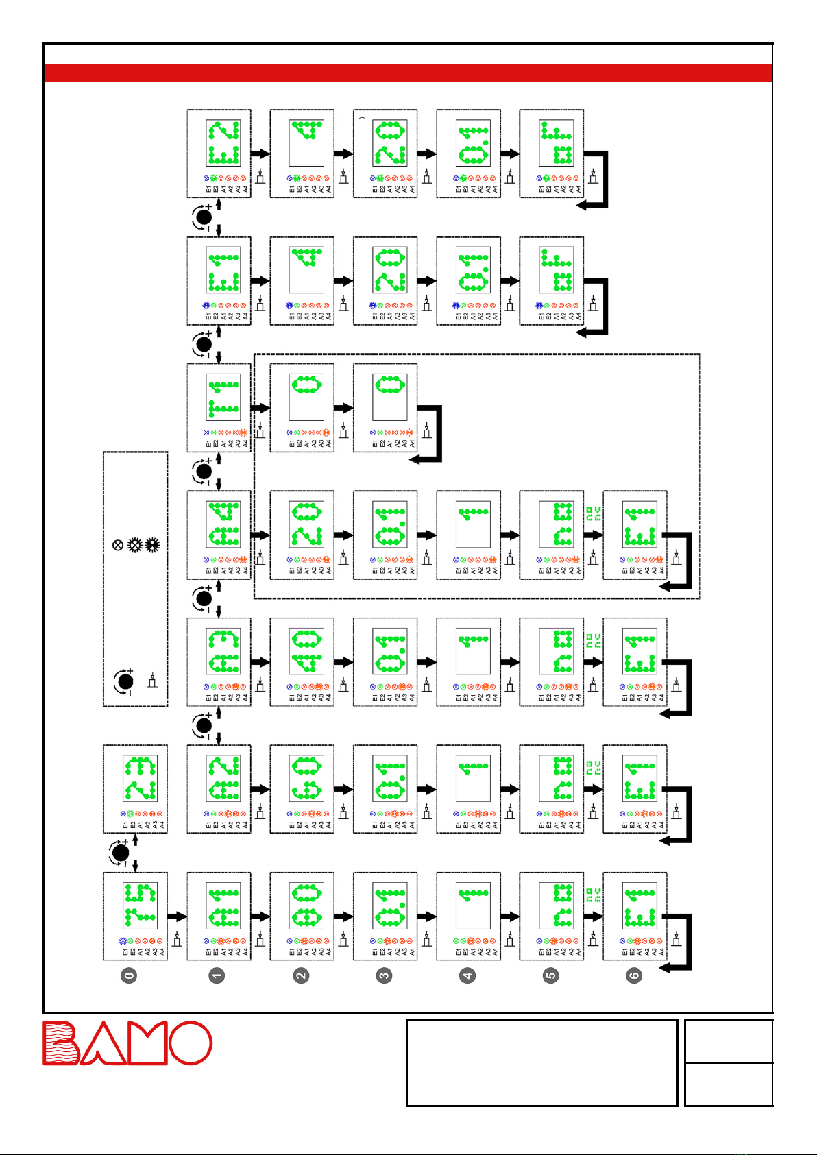
Display 2 ½ digit LED 5x7 dot matrix display
4x LED = limit value relay status
1x Blue LED = input 1
1x Green LED = input 2
Display resolution 1 %
Settings Combined rotary / pressure switch
Electrical connection Screw terminals, cable cross section Max. 1.5 mm²
Note:
Protection against accidental contact according to DIN EN 61010-1 is only guaranteed when installed in a closed housing with at least
protection class IP54.
Ambient temperature -10 ... +45 °C
Housing: For DIN rail 35 x 7.5 mm (DIN EN 50 022); Protection class IP40 according to EN 60 529
EC Conformity: The instrument meets the legal requirements of the current European Directives.
MAINTENANCE
Everest 214-S is maintenance-free if used for its intended purpose.
RE
10-02-2022 M-232.04-EN-AB 232-04/3
4 limit value relays
EVEREST 214-S
22, Rue de la Voie des Bans · Z.I. de la gare · 95100 ARGENTEUIL
Tel
Fax
+33 (0)1 30 25 83 20
+33 (0)1 34 10 16 05
Web
E-mail
www.bamo.eu
INTERNATIONAL

OPERATING THE EVEREST 214S
After switching on the supply voltage, the device starts a test routine in which all LEDs and the digital display are activated (LEDs test).
After ≈1 second the software version is displayed for a short time.
Then the display jumps to menu level 0 (measured value display).
Power
Power supply
galvanic isolated
Signal
processing
Display
CONTROLS
See diagram of operating menu at the end of document
Rotary / push switch: turning +/-
Menu level 0 = Selection of display of input 1 or input 2
Menu level 1 = selection setting of the limit value for relays 1 to 4
Menu level 2 to 6 = set values +/-
Rotary / push switch: pressing
Selection of submenus 1 to 6
If the control button is not pressed within 15 s, the system automatically switches back to the measured value display (menu 0).
LIMIT RELAY 1 to 4
Yellow LED lights up = relay pulled in = contact is closed
LIMIT VALUE
Setting from 2 to 100%
relative to the selected mA- or MIN- or MAX range
The threshold value cannot be set smaller than or equal to the currently set hysteresis.
Default setting: A1 = 80%, A2 = 60%, A3 = 40%, A4 = 20%
DELAY
Adjustable from 0.1 to 9.9 s
Exceeding, or falling below, the limit value --> after set delay the relay switches
Default setting: 0.1 s
RE
10-02-2022 M-232.04-EN-AB 232-04/4
4 limit value relays
EVEREST 214-S
22, Rue de la Voie des Bans · Z.I. de la gare · 95100 ARGENTEUIL
Tel
Fax
+33 (0)1 30 25 83 20
+33 (0)1 34 10 16 05
Web
E-mail
www.bamo.eu
INTERNATIONAL

HYSTERESIS
Setting from 1 to 99 %
The output relay only switches back when the measured value has fallen below the selected percentage.
The hysteresis cannot be set greater than or equal to the currently set threshold value.
Default setting: 1%
NC or NO SELECTION
NO (normally open): The contact is open as long as the measured value is lower than the set threshold value
NC (normally closed): The contact is closed as long as the measured value is lower than the set threshold value
Default setting: NO
Note: in the event of a power failure or device defect, all relay contacts are open
ASSIGNING OUTPUT RELAY TO INPUT E1 OR E2
The measured value of input E1 or E2 can be assigned to each individual output relay A1 to A4.
Factory setting: all relays are assigned to input 1 (E1)
OVER-RANGING DISPLAY
Measuring signal > mA max. value -> digital display = ↑
Measuring signal < mA min. value -> digital display = ↓
CLOCK-TIMER
Alternatively, relay 4 can also be used as a timer. The timer discount is switched on as soon as the ON and OFF times are set greater than 0.
--> This means that the settings for limit value relay 4 become ineffective.
ON-TIME
As long as the set ON-time is running, the contact of output relay 4 is closed
Setting range: 1 second to 24 hours
Available setting values:
0*, 1, 2, 5, 10, 30 secondes
→ no additional dot lights up
1, 2, 5, 10, 30 minutes
→ 1 additional dot light is blinking
1, 2, 3, 6, 12, 24 hours
→ 2 additional dot lights are blinking
Default setting: 0
= 10 s = 10 min = 12 h
OFF - time setting
As long as the set OFF time is running, the contact of output relay 4 is open
Settings as above
Default setting: 0
Note: After a power failure the device reboots, the program starts with the ON-Time
If one of the times is changed during operation, the new time takes effect immediately.
RE
10-02-2022 M-232.04-EN-AB 232-04/5
4 limit value relays
EVEREST 214-S
22, Rue de la Voie des Bans · Z.I. de la gare · 95100 ARGENTEUIL
Tel
Fax
+33 (0)1 30 25 83 20
+33 (0)1 34 10 16 05
Web
E-mail
www.bamo.eu
INTERNATIONAL

SCALING INPUT 1 AND 2
mA min. value:
Setting range: 0 to 24 mA
Default setting: = 4 mA
mA max. value:
Setting range: 1 to 25 mA
Default setting: = 20 mA
In the Scaling menu, the percentage display can be assigned to a range of the mA measuring signal.
DisplayInput signal
Menu measuring windows min
Menu measuring windows max
Example E1: required setting:
Measuring signal 5 mA = display of 0% Menu: Scaling E1 / mA min. = 5
Measuring signal 18 mA = display of 100% Menu: Scaling E1 / mA max. = 18
FILTER (DAMPER)
Filter for attenuating fluctuations on measured values and interferences
Integration time adjustable from: 0.1 to 9.9 s
Default setting: 0.1 s
HOLD FUNCTION
For each one of both inputs a hold function can be activated
This makes it possible to hold the last measured value while the timer is active (relay A4).
Available setting values:
oF: Hold function switched off (factory setting)
on: Hold function switched on
The hold function only works when the timer (A4) is activated (on-time)
RESET TO FACTORY DEFAULT SETTINGS
Switch on the power supply
Within 3 seconds (i.e. during the test routine), press the pushbutton for approximately 5 seconds.
Display counts up
1, 2, 3, 4, ... 99, ST ....
→ all setting values are reset to the values of the factory setting
(Default values)
RE
10-02-2022 M-232.04-EN-AB 232-04/6
4 limit value relays
EVEREST 214-S
22, Rue de la Voie des Bans · Z.I. de la gare · 95100 ARGENTEUIL
Tel
Fax
+33 (0)1 30 25 83 20
+33 (0)1 34 10 16 05
Web
E-mail
www.bamo.eu
INTERNATIONAL

OPERATING MENU
Measuring value E1 (%)
Turn knob
Press knob
= LED OFF
= LED on
= LED flashes
Select relay 1
Limit value (%)
Delay time (s)
Hysteresis (%)
Opening or Closing
Assign. E1 or E2
Closing
Opening
Back to
Relay 1
Level 1
Relay 2 Relay 3
Back to
Level 1
Back to
Level 1
Back to
Level 1
Relay 4
or
Clock-timer
Closing
Opening
Closing contact
Opening contact
Closing contact
opening contact
Measuring value E2 (%)
Select relay 2
Limit value(%)
Delay time (s)
Hysteresis (%)
Opening or Closing
Assign. E1 or E2
Select relay 3
Limit value (%)
Delay time (s)
Hysteresis (%)
Opening or Closing
Assign. E1 or E2
Select relay 4
Limit value (%)
Delay time (s)
Hysteresis (%)
Contact: Opening or Closing
Assign. E1 or E2
Select clock-timer
OFF-time
ON-Time
Back to
Level 1
Select input 1
Measuring window min (mA)
Filter time (s)
Hold function
Select input 2
Measuring window min (mA)
Measuring window max (mA)
Filter time (s)
Hold function
Back to
Level 1
Back to
Level 1
Input 2 Input 2
RE
10-02-2022 M-232.04-EN-AB 232-04/7
4 limit value relays
EVEREST 214-S
22, Rue de la Voie des Bans · Z.I. de la gare · 95100 ARGENTEUIL
Tel
Fax
+33 (0)1 30 25 83 20
+33 (0)1 34 10 16 05
Web
E-mail
www.bamo.eu
INTERNATIONAL

ELECTRICAL CONNECTIONS
Examples for connections of sensors: 2-wire or 3/4-wire sensors
Sensor 1: 4-wire Sensor 2 (e.g. Turbicube):
3-wire
Sensor 1: 2-wire Sensor 2: 2-wire
Fuse
Fuse
Power supply
Power supply
Output
Output
Interface for Datalogger or
Digital Sensor
Interface for Datalogger or
Digital Sensor
Reporting and control device
Control and Indication Device
100 Ω
100 Ω
100 Ω
100 Ω
10 ... 30 VDC
100 ... 250 V AC
10 ... 30 V DC
100 ... 250 V AC
RE
10-02-2022 M-232.04-EN-AB 232-04/8
4 limit value relays
EVEREST 214-S
22, Rue de la Voie des Bans · Z.I. de la gare · 95100 ARGENTEUIL
Tel
Fax
+33 (0)1 30 25 83 20
+33 (0)1 34 10 16 05
Web
E-mail
www.bamo.eu
INTERNATIONAL
Table of contents
Other Bamo Relay manuals