Bamo ES2001 User manual

ELEKTRODENSTEUERUNG ES2001
INSTRUCTION MANUAL
SAFETY INSTRUCTIONS
- Installation, commissioning and maintenance may only be performed by
qualified personnel!
- nly connect the unit to the voltage specified in the technical data or on the type
plate (observe polarity for DC)!
- The device must be disconnected from all sources of power during installation
and maintenance work.
- The device may only be operated under the conditions specified in the operating
instructions.
TECHNICAL DATA
Power supply 230, 115, 48, 24 V±10% AC 50/60 Hz; 24, 12 VDC
Connected load ≤ 2 VA
Relay output 2 changeover contacts, potential-free
AC: Max. 250 V, 5 A, 500 VA
DC: Max. 125 V, 1 A, 40 W
Measuring circuit Galvanically isolated, AC voltage < 6 V / < 2 mA
Measuring function MIN-MAX control
MIN control or MAX control
Hysteresis About 20% of the set sensitivity value
Response sensitivity 2 adjustable ranges
1 to 70 kΩ & 5 to 150 kΩ
Working principle Open / Closed curent lopp
Delay ON/OFF delay adjustable: 0.5 to 3 s
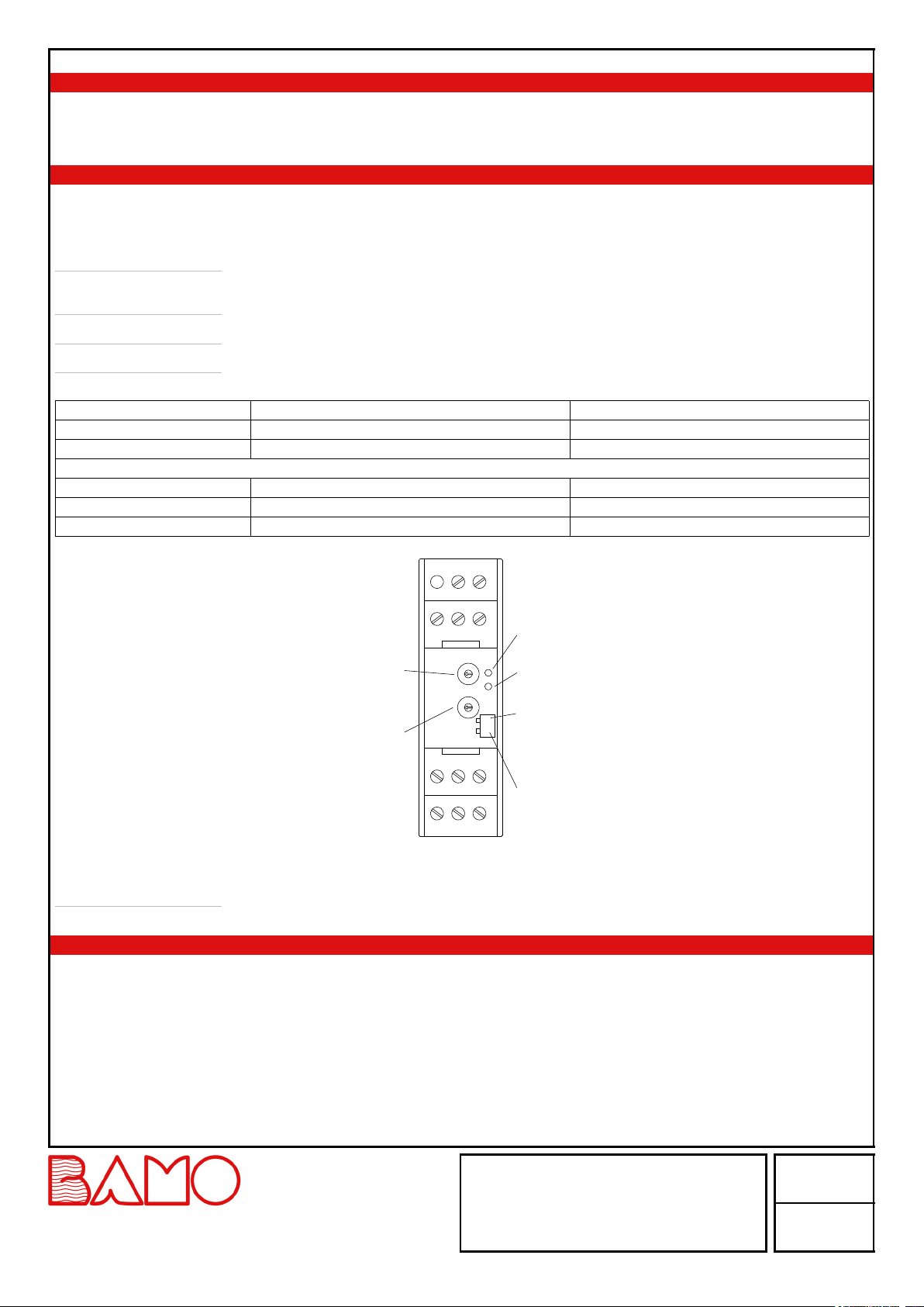
Adjustment through potentiometer
Ambient temperature -15 ... +45 °C
Dimension 22.5 x 75 x 100 mm
Housing IP40, mounting DIN rail 35x7.5 mm (EN50022); Option: IP55 wall-mount cabinet 88x150x130mm
Cable min. Wire cross-section 0.5mm², shielded cable
Electrical connections IP20, screw terminals, cable cross-section max 2.5 mm²
Signalling 1x LED: ''Operating''
1x LED: ''Status of relay''
EC Conformity: The instrument meets the legal requirements of the current European Directives.
OPERATING RANGE
The capacitive resistance of long cables reduces the sensitivity of the detection.
A standard 3-wire PVC cable has a capacitance of 100 pF/m
The range therefore depends on the liquid resistance and on the cable length between the electrode and the relay ES2001.
This results in an operating range according to the diagram below:
Liquid resistance [ kΩ ]
Outside the operating range
Operating range
Cable length [ m ]
LEV
06-06-2023 M-530.01-EN-AB 530-01/1
INSTRUCTION MANUAL
ELEKTRODENSTEUERUNG ES2001
22, Rue de la Voie des Bans · Z.I. de la gare · 95100 ARGENTEUIL
Tel
Fax
+33 (0)1 30 25 83 20
+33 (0)1 34 10 16 05
Web
E-mail
www.bamo.eu
INTERNATIONAL

RECOMMENDATIONS FOR THE CABLE
- Use a multi-core cable of 0.5 mm².
- This cable must be separated from other cables.
- Above 25 m length, it is necessary to use a shielded cable.
SETTINGS
The transparent front panel can be removed by levering it out, gently, with a screwdriver.
Sensitivity Potentiometer P1 and DIP S2
To adaptat the sensitivity to the liquid conductivity.
Note The poorer the liquid conductivity and greater the distance between electrodes, the higher the response
sensitivity must be set.
Caution An excessive sensitivity leads to faulty triggering.
Open / Closed current loop DIP S1
Delay Potentiometer P2: To prevent multiple switching with waves on the liquid surface.
Potentiometer Anticlockwise Right stop
P1 Sensitivity Minimum Maximum
P2 Delay approx. 0.5 seconds approx. 3 seconds
DIP switch ON OFF
1 Current in the loop No current
2 High sensitivity 5 to 150 kΩ Low sensitivity 1 to 70 kΩ
LED yellow
"Output relay"
LED green
"Ready for
operation"
DIP switch 2
"Sensitivity"
DIP switch 1
"Working/resting
current"
Potentiometer P2
"Delay time"
Potentiometer P1
"Sensitivity"
Signalling:
Green LED lights up Unit ready for operation
Yellow LED lights up Output relay status is changed
MAINTENANCE
When used as intended, the device is maintenance-free.
LEV
06-06-2023 M-530.01-EN-AB 530-01/2
INSTRUCTION MANUAL
ELEKTRODENSTEUERUNG ES2001
22, Rue de la Voie des Bans · Z.I. de la gare · 95100 ARGENTEUIL
Tel
Fax
+33 (0)1 30 25 83 20
+33 (0)1 34 10 16 05
Web
E-mail
www.bamo.eu
INTERNATIONAL

L(+)
N(-)
L+N-
E0E2E1
242122
11 1412
DP0032
ON
1 2
L(+)
N(-)
L+N-
E0E2E1
242122
11 1412
DP0033
ON
1 2
ELECTRICAL CONNECTIONS
1/ One trigger point: 2 electrodes
The relay is energised as soon as the liquid forms an electrical bridge between the level electrode and the reference electrode (or metal tank
wall).
Fill container
Reference electrode
MAX electrode
MIN electrode
K1
ES 2001
Relay max:
250V AC / 5A / 500VA
125V DC / 1.5A /40W
Relay of the filling pump activates when MIN-electrode becomes free; ...drops off when MAX electrode is immersed
Drain container
Reference electrode
MAX electrode
MIN electrode
K1
ES 2001
Relay max:
250V AC / 5A / 500VA
125V DC / 1.5A /40W
Relay of the drain pump activates when MAX electrode immerses; ...drops off when MIN electrode becomes free
LEV
06-06-2023 M-530.01-EN-AB 530-01/3
INSTRUCTION MANUAL
ELEKTRODENSTEUERUNG ES2001
22, Rue de la Voie des Bans · Z.I. de la gare · 95100 ARGENTEUIL
Tel
Fax
+33 (0)1 30 25 83 20
+33 (0)1 34 10 16 05
Web
E-mail
www.bamo.eu
INTERNATIONAL

L(+)
N(-)
L+N-
E0E2E1
242122
11 1412
DP0034
ON
1 2
L(+)
N(-)
L+N-
E0E2E1
242122
11 1412
DP0035
ON
1 2
ELECTRICAL CONNECTIONS (continuation)
2/ Automation of filling or draining: 3 electrodes
The self-holding function between two trigger points is carried out via the third electrode.
A diode on the front panel indicates the status of the relay.
It lights up as soon as the relay is energised.
Dry run protection
Reference electrode
MIN electrode
K1
ES 2001
Relay max:
250V AC / 5A / 500VA
125V DC / 1.5A /40W
Dry run protection:
Relay of the drain pump drops off when MIN electrode becomes free or in case of malfunction/power failure/cable breakage of the electrode
control unit
Overfill alarm
reference electrode
MAX electrode
K1
ES 2001
Relay max.:
250V AC / 5A / 500VA
125V DC / 1.5A / 40W
Overflow alarm (0-signal):
Alarm signalling relay K1 drops off when MAX electrode immerses or in the case of malfunction/voltage failure of the electrode control system
Overflow alarm (1-signal):
Alarm signalling relay K1 activates when MAX electrode immerses or in case of malfunction/voltage failure of the electrode control
---> Connect relay K1 to terminal 12
TESTING THE RELAY:
- Disconnect the electrodes from the relay ES2001
- Short circuit E0 and E2 → the relay is activated (alarm function)
- Short circuit in the order E0, E2 and E1 → Enable E2 then E1 (control function)
LEV
06-06-2023 M-530.01-EN-AB 530-01/4
INSTRUCTION MANUAL
ELEKTRODENSTEUERUNG ES2001
22, Rue de la Voie des Bans · Z.I. de la gare · 95100 ARGENTEUIL
Tel
Fax
+33 (0)1 30 25 83 20
+33 (0)1 34 10 16 05
Web
E-mail
www.bamo.eu
INTERNATIONAL
Other Bamo Relay manuals
Popular Relay manuals by other brands

Schweitzer Engineering Laboratories
Schweitzer Engineering Laboratories SEL-321-2 instruction manual

ERL
ERL B-PRO user manual

Valcom
Valcom VM-SRLY quick start guide

Siemens
Siemens SIRIUS 3RT161 1A 3 Series Original operating instructions

FMX
FMX FSR-TDUV Series quick start guide

Salus
Salus SR600 Full user manual