B&B SF1600TL User manual

Solar Family PV Grid-tied Inverter
User Manual

The Solar Family Series Inverter
I
Table of Contents
1 Notes....................................................................................................................................................1
1.1 Validity......................................................................................................................................1
1.2 Target Group..............................................................................................................................1
1.3 Safety.........................................................................................................................................1
2 Introduction.........................................................................................................................................6
2.1 Overview....................................................................................................................................6
2.2 Electrical Block Diagram...........................................................................................................6
2.3 Terminals of PV Inverter...........................................................................................................7
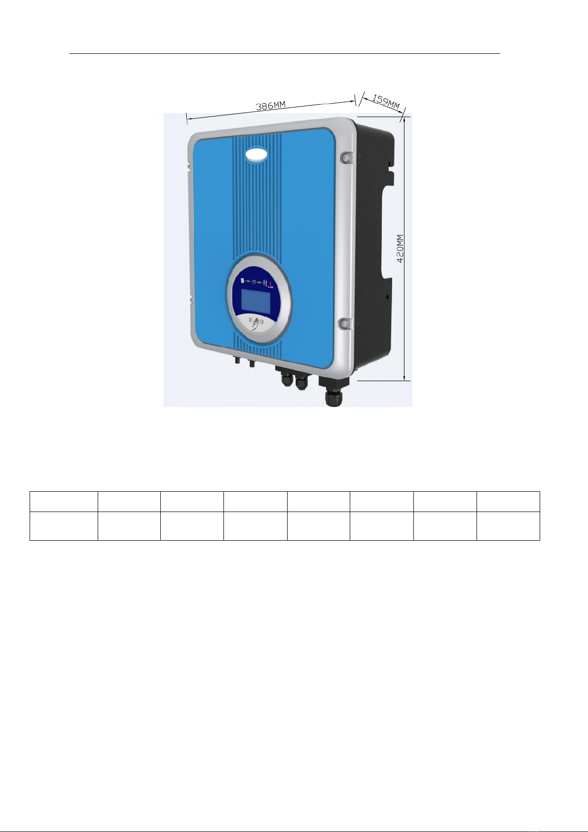
2.4 Dimension and Weight ..............................................................................................................7
3 Packaging List....................................................................................................................................9
4 Technical Data.................................................................................................................................10
4.1 Input(DC)...........................................................................................................................10
4.2 Output(AC).........................................................................................................................10
4.3 Efficiency Safety and Protection..............................................................................................11
4.4 General Data ............................................................................................................................11
5 Function.............................................................................................................................................13
6 Installation.........................................................................................................................................14
6.1 Safety Instructions ...................................................................................................................14
6.2 Selecting the Installation location............................................................................................14
6.3 Preparation...............................................................................................................................15
6.4Monuting the Bracket ...............................................................................................................15
6.5Mounting the Inverter...............................................................................................................17
6.6 Check Inverter Installation Status............................................................................................18
6.7 Connector Guide......................................................................................................................18
7 Operation ..........................................................................................................................................21
7.1 LED Display............................................................................................................................21
7.2 LCD Display............................................................................................................................22
8 Setting up Communication.............................................................................................................28
8.1 Communication Interface Type ...............................................................................................28
8.2 Communication........................................................................................................................28
9 Troubleshooting...............................................................................................................................31
10 Decommissioning ..........................................................................................................................33
10.1 Dismantling............................................................................................................................33
10.2 Packaging...............................................................................................................................33
10.3 Storage...................................................................................................................................33
10.4 Disposal .................................................................................................................................33
11 Warranty..........................................................................................................................................34

The Solar Family Series Inverter
1
1 Notes
This manual is an integral part of the inverter. Please read the product manual carefully before
installation, operation or maintenance. Keep this product manual for future reference.
1.1 Validity
This manual describes the assembly, installation, commissioning and maintenance of the following
inverters:
SF1600TL SF2200TL SF3000TL
SF3600TL SF4200TL SF4600TL SF5000TL
1.2 Target Group
This manual is for qualified personnel who have received training and demonstrated skills and
knowledge in the construction and operation of this device.
Qualified personnel are trained to deal with the dangers and hazards involved in installing electric
devices.
1.3 Safety
1.3.1 Appropriate Usage
The Solar Family Series are the PV inverters which convert the DC current of a PV generator into
AC current and feed it into the public grid.
Figure 1 PV Grid-tied System
PV Module Grid-tied inverter
Grid

The Solar Family Series Inverter
2
1.3.2 Important Safety Instructions
Danger!
Danger to life due to high voltages in the inverter!
·All work on the inverter must be carried out by qualified personnel
only.
·The inverter is forbidden to be operated by children or persons with
limited physical or mental capabilities, persons who la
ck of
experience and knowledge can only operate the inverter under the
condition of being given supervision or instruction.
·Children should be supervised to ensure that they do not play with
the inverter.
Caution!
Danger of burn injuries due to hot enclosure parts!
·During operation, the upper lid of the enclosure and the enclosure
body may become hot.
·Only touch on the lower enclosure lid is allowed during operation.
Caution!
Possible damage to health as a result of the effects of radiation!
·Do not stay closer to the inverter (beyond 20cm is available) for a
long time.
Note!
Grounding the PV generator.
·Please recommend PV modules have an IEC 61730 Class A rating.
Please don’t connect the PV modules to GND.

The Solar Family Series Inverter
3
1.3.3 Glossary of Symbols
This section gives a glossary of all the symbols shown on the inverter and the type label.
●Symbols on the inverter
Symbol
Explanation
Danger to life due to high voltages in the inverter!
•There would be residual voltage in the inverter. The inverter requires
1 minute to discharging.
• Wait for 5 minutes before you open the upper lid or the DC lid.
Beware of hot surface.
·The inverter may become hot during operation. Avoid any contact to
the surface during operation.
Danger of high voltages
·Danger to life due to high voltages in the inverter!
Risk of electric shock!
·Only authorized personnel is allowed to set the DIP switch (SW1).
Requests the user to consult the manual
Indicates caution followed by important instructions
Equipment grounding conductor
AC voltage
You can operate the interface by tapping on it
·Tapping once: The background illumination switches on.
·Tapping again: Updating information.
Recovery and recycling.

The Solar Family Series Inverter
4
●Symbols on the type label
Symbol Explanation
CE mark.
·The inverter complies with the requirements of the applicable CE
guidelines.
TUV mark.
·The inverter complies with the requirements of the applicable TUV
guidelines.
SAA mark.
·The inverter complies with the requirements of the applicable SAA
guidelines.
G59 mark.
·The inverter complies with the requirements of the applicable G59
guidelines.
G83 mark.
·The inverter complies with the requirements of the applicable G83
guidelines.
CQC mark.
•The inverter complies with the requirements of the applicable CQC
guidelines.
、
●Safety precaution
When using the product, please do remember the below information to avoid the fire, lightning or
other personal injury:
Warning!
Ensure that input DC voltage is less than Max. DC voltage.
·Over voltage may cause permanent damage to inverter or other
losses, which will not be included in warranty!
·This chapter contains important safety and operating instructions.
·Read and keep this operation Guide for future reference.

The Solar Family Series Inverter
5
Warning!
· Authorized service personnel must disconnect both AC and DC
power from the SF series inverter before attempting any
maintenance or cleaning or working on any circuits connected to
the SF series inverter.
Warning!
· The photovoltaic array is exposed to sunlight, it supplies DC voltage
to the inverter.

The Solar Family Series Inverter
6
2 Introduction
2.1 Overview
Figure 2 Stereogram
2.2 Electrical Block Diagram
●Electrical block diagram
Figure 3 Electrical block diagram

The Solar Family Series Inverter
7
2.3 Terminals of PV Inverter
Figure 4 Terminals of PV Inverter (SF1600TL/SF2200TL/SF3000TL)
Figure 5 Terminals of PV Inverter (SF3600TL/SF4200TL/SF4600TL/SF5000TL)
2.4 Dimension and Weight
●Dimension
Figure6SF1600TL/ SF2200TL/ SF3000TL
RS485
RS485

The Solar Family Series Inverter
8
Figure7SF3600TL/ SF4200TL/ SF4600TL/SF5000TL
●Weight
Table 1
Model
SF1600TL
SF2200TL
SF3000TL
SF3600TL
SF4200TL
SF4600TL
SF5000TL
Weight [kg] 13.6 13.9 13.9 17.2 17.5 17.5 17.5

The Solar Family Series Inverter
9
3 Packaging List
Table 2
The Solar Family is shipped with the following items:
Figure 8
Item Name Quantity
ASolar Inverter 1
BMounting Frame 1
CMounting Screws 4
DMounting Frame Screws Sleeve 4
EMounting Screws 2
F Manual 1
F

The Solar Family Series Inverter
10
4 Technical Data
4.1 Input(DC)
Table 3
Model SF1600TL SF2200TL SF3000TL SF3600TL SF4200TL SF4600TL SF5000TL
Max. DC
Power[W] 1700 2350 3150 3800 4400 4800 5200
Max. DC power
each MPP tracker
[W] 1700 2350 3150 3000
Max. DC
Voltage[V] 550 550
Max.Input
Current of MPP
Tracker[A] 13 15 15/15
Number of MPP
Trackers / Strings
per MPP Tracker 1/1 2/1
MPPT Voltage
Range [V] 120-500 170-500 210-500 120-500 150-500 160-500 175-500
Nominal PV
Voltage [V] 360 360
Start
Voltage/On-Grid
Voltage 100/120 100/120
Overvoltage
category ⅡⅡ
4.2 Output(AC)
Table 4
Model SF1600TL SF2200TL SF3000TL SF3600TL SF4200TL SF4600TL SF5000TL
Max. AC
Power[W] 1600 2200 3000 3600 4200 4600 5000
Max. AC Current
[A] 7.8 11 14.5 18 21 22 24
Nominal AC
Voltage [V] 220/230/240 220/230/240
AC Voltage
Range [V] 176-276 176-276
AC Grid
Frequency [Hz] 50/60 50/60

The Solar Family Series Inverter
11
Power Factor
(cosφ) 0.8lagging-0.8leading 0.8lagging-0.8leading
THD
(at nominal
power) <3% <3%
Overvoltage
Category ⅢⅢ
*Maximum Output power limited to 16amps up to a maximum power of 3.6KW, for G83.
Maximum Output power limited to 18amps up to a maximum power of 3.6KW, for G59.
4.3 Efficiency Safety and Protection
Table 5
Model SF1600TL SF2200TL SF3000TL SF3600TL SF4200TL SF4600TL SF5000TL
Max. Efficiency 97.7% 97.8% 97.8% 98.1% 98.1% 98.1% 98.1%
Euro-Efficiency 97.0% 97.1% 97.2% 97.3% 97.4% 97.5% 97.6%
MPPT Efficiency 99.9% 99.9%
Overvoltage /
Under-
Voltage Protection Yes Yes
Shutdown
Voltage / Start
Voltage Yes Yes
DC Isolation
Impedance
Monitoring Yes Yes
Ground Fault
Protection Yes Yes
Grid Monitoring Yes Yes
Ground Fault
Current
Monitoring Yes Yes
DC Injection
Monitoring Yes Yes
4.4 General Data
Table 6
Model SF1600TL SF2200TL SF3000TL SF3600TL SF4200TL SF4600TL SF5000TL
Dimension(W/H/
D) [mm] 386/340/159 386/420/159
Weight [kg] 13.6 13.9 13.9 17.2 17.5 17.5 17.5
Cooling Concept Natural Convection Natural Convection

The Solar Family Series Inverter
12
Noise (typical)
[dB] <30 <30
Operating
Temperature
Range [°C] -25℃~+60℃/derating at 45℃-25℃~+60℃/derating at 45℃
Relative humidity
range 4% ~ 100% (condensing) 4%~ 100% (condensing)
Pollution Degree External (III) Internal (II) External (III) Internal (II)
Protective class ClassⅠClassⅠ
Degree of
Protection IP65 IP65
Topology Transformerless Transformerless
Internal
Consumption( ni
ght ) [W] <0.5W <0.5W
LCD display Yes Yes
Communication
Interfaces RS485/ WiFi optional RS485/ WiFi optional
Standard
Warranty
6/10/15 years
Free/opt./opt.
6/10/15 years
Free/opt./opt.

The Solar Family Series Inverter
13
5 Function
Operation Condition
【Waiting Mode】
When DC voltage is over 100V but doesn’t reach to 120V, the inverter enters a "Waiting mode".
Under this mode, it will continue checking if PV array has enough power to feedback into grid.
【Self Testing Mode】
After initialization is finished in "Waiting mode", if the PV voltage is over 120V and the grid voltage
& frequency meet the standard, the inverter will work in the "Self-Testing mode".
【On-grid Mode】
Under this mode, SF series inverters convert PV array’s DC into AC and feedback into grid.
【Fault Mode】
If any fault/error occurs, inverter stops generating power until the fault/error is cleared. Some
fault/error will recover itself, and some may need to restart manually to resolve.
CAUTION!
The inverter output power decrease is usual under
the condition of thermal
protection, but if it occurs frequently, you need to check the heat sink or consider
putting the inverter in the place where have better air flow, and if output power
decreases caused by electrical problem, please ask for professional supports.

The Solar Family Series Inverter
14
6 Installation
6.1 Safety Instructions
Do not remove the enclosure upper lid. Inverter contains non-user practical parts. All wiring and
electrical installation should be conducted by a qualified service personnel and must meet national
requirements.
Both AC and DC voltage sources are terminated inside the PV Inverter. Please disconnect these
circuits before servicing.
When a photovoltaic panel is exposed to sunlight, it generates DC voltage. When connected to this
equipment, a photovoltaic panel will charge the DC capacitors.
Energy stored in this equipment’s DC capacitors presents a risk of electric shock. Even after the
unit is disconnected from the grid and photovoltaic panels, high voltages may still exist inside the
PV-Inverter. Do not remove the upper lid until at least 5 minutes after disconnecting all power
sources.
This unit is designed to feed power to the public power grid only. Do not connect this unit to an AC
source or generator. Connecting inverter to external devices could result in serious damage to your
equipment.
Carefully remove the unit from its packaging and inspect for external damage. If you find any
imperfection, please contact with your local distributor or service center.
Although designed to meet all safety requirements, some parts and surfaces of inverter are still hot
during operation. To reduce the risk of injury, DO NOT touch the heat sink at the back of the
PV-Inverter or nearby surfaces while Inverter is operating.
Check environment where system is installed.
Check whether the installation site fall into any of the following conditions:
● The ambient temperature is beyond the range of the optional temperature limitation. ( -25°C to
+60°C, -13°F to +140°F),(Power derating begins at 45°C).
● Installation altitude is higher than 2000m.
● Prone to be damaged by sea water
● Close to corrosive gas or liquid (for example, locations where chemicals are processed or the
location where feed lots of poultry).
● Exposed to direct sunlight.
● Prone to be damaged in flooding or icing time
● Little air flow or high humidity.
● Exposed to steam, vapor, or water.
● Exposed to direct cool air.
● Close to the television antenna or antenna cable.
6.2 Selecting the Installation location
The installation method and mounting location must be suitable for the weight and dimensions of
the inverter. Select a wall or solid vertical surface which is able to support the PV Inverter.
Mount on a solid surface, the mounting location must be accessible at all times.
Vertical installation or tilted backwards by max. 15°.
The connection area must point downwards.

The Solar Family Series Inverter
15
Do not install horizontally.
Figure 9
6.3 Preparation
Below tools are needed before installation.
Figure 10 Installation Tools
6.4 Mounting the bracket
Inverter requires adequate cooling space. Allow at least 20cm space above and below the inverter.
Figure 11

The Solar Family Series Inverter
16
Using the mounting frame as a template, drill 3 holes as illustrated in image
Figure 12
Fix the mounting frame as the figure shows. Do not make the screws too close to the wall, leaving
2-4mm exposed instead.
Figure 13

The Solar Family Series Inverter
17
6.5 Mounting the Inverter
Hang the inverter onto the mounting frame.
Figure 14
Insert safety- lock screws into the bottom leg to fasten the inverter.
Figure 15

The Solar Family Series Inverter
18
6.6 Check Inverter Installation Status
Check the upper straps of Inverter to ensure it is fixed on to the bracket
Check the secure mounting of the PV-Inverter by trying to raise it from the bottom.
The PV-Inverter should remain firmly attached.
Select the installation location so that the status of display can be easily viewed.
Choose a strong mounting wall to prevent vibrations while inverter is operating.
6.7 Connector Guide
This product has a professional IP68 DC waterproof connector. You have to wire DC by yourself.
Please see Figure 16 and Figure 17 for DC connector disassembling guide.
Connectors must only be connected by qualified personnel
Only PV1-F cables can be used. The TÜV approval only allows the use of PV1-F cables. Do not
use type H07RN-F cables.
The connectors must be not disconnected while under load. For protection against electric shock,
connectors must always be disconnected from the power supply during assembly.
Connectors that are not plugged must be protected against humidity and contamination by a
protective cap. Any kind of contamination may have adverse effect on the system and great care
must be taken during assembly to ensure that everything is clean.
Connectors provide IP68 protection but should not be continually exposed to water (e.g. immersed
under water) and not placed directly on the top side.
Connecting to PV panel (DC input):
Figure 16
1. Insert the stripped conductor.
Cross-sections: 2.5 to 6 mm2
Outside diameter: 5.0 to 8 mm
Stripping length: 15 mm
2. Close spring with the thumb or using combination pliers.
This manual suits for next models
6
Table of contents
Popular Inverter manuals by other brands

Danfoss
Danfoss VLT AutomationDrive FC 300 Design guide

Olympus
Olympus CelonLab ENT Instructions for use

YASKAWA
YASKAWA XGI 1000-65/65 Installation and operation guide

Agilent Technologies
Agilent Technologies PSG Series Installation note

Siemens
Siemens Sinamics CU240D-2 DP operating instructions

EG4
EG4 6000XP user manual

Growatt
Growatt MAX Series Installation & operation manual

SMA
SMA SWR 2500U - V1.2 Installation and operator's manual

GS Energy
GS Energy GS-hybrid-3K user manual

Pure Sine Wave Generators
Pure Sine Wave Generators DG-3500 operating instructions

Huawei
Huawei SUN2000-(25KTL, 30KTL)-US installation guide

Fairland
Fairland TurboSilence IXCR26V manual