Thermia Diplomat Inverter Mini User manual

Thermia AB is not liable or bound by warranty if these
instructions are not adhered to during installation or service.
The English language is used for the original instructions.
Other languages are a translation of the original instructions.
(Directive 2006/42/EC)
© Copyright Thermia AB

Table of Contents
1 About the document .............................................................. 4
1.1 About the dokument ........................................................... 4
1.2 Important information .......................................................... 4
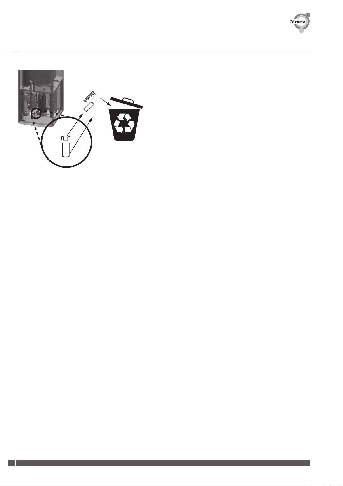
1.3 Scrapping .................................................................. 4
1.4 Water quality ................................................................ 5
1.5 Maximum length of collectors ..................................................... 5
1.6 Overview image .............................................................. 6
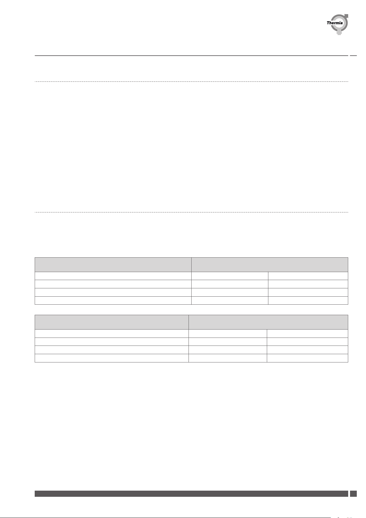
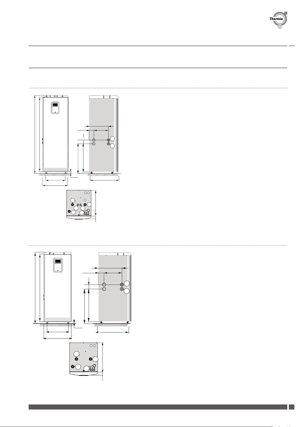
2Heat pump data, dimensions and connections ............................................ 7
2.1 Diplomat Inverter Mini .......................................................... 7
2.2 Diplomat Duo Inverter Mini ....................................................... 7
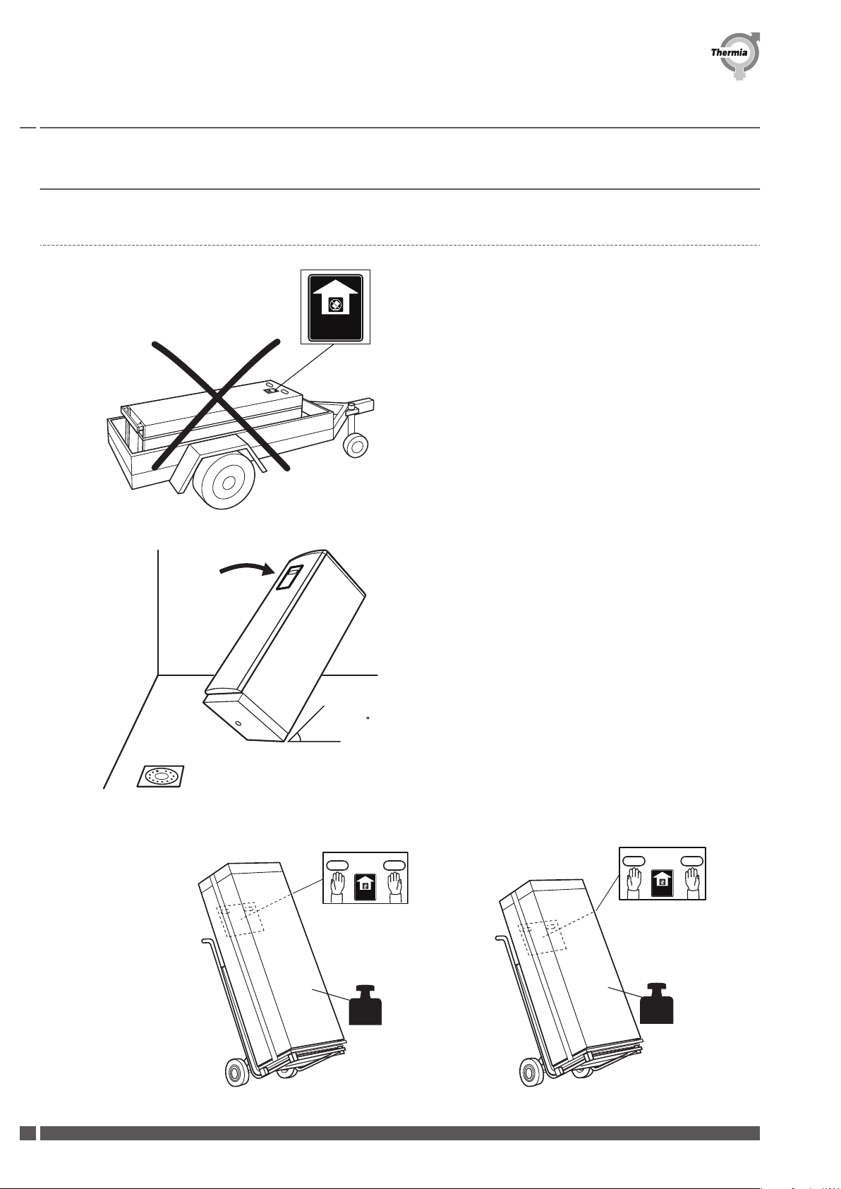
3Transportation, space requirement and Recommended location ................................ 8
3.1 Transportation ............................................................... 8
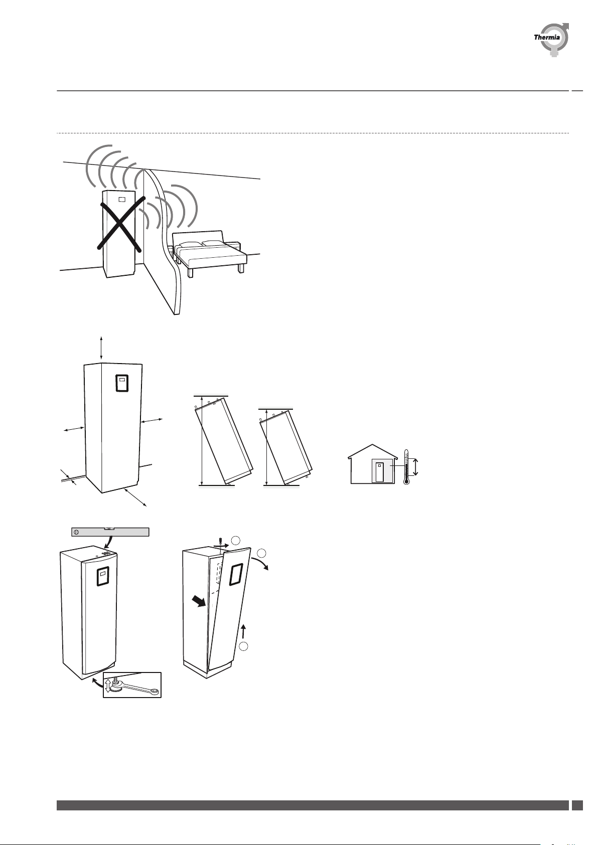
3.2 Space requirement and recommended location ......................................... 9
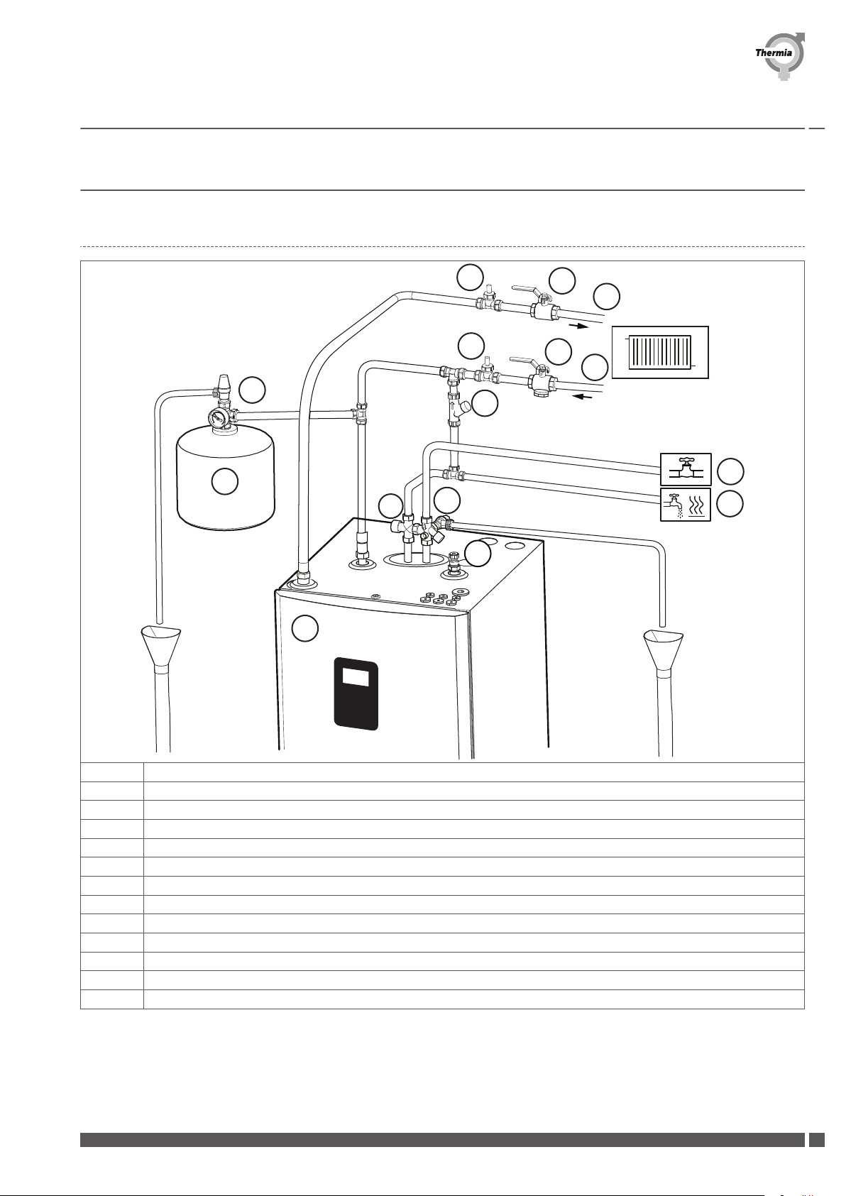
4Heating connections .............................................................. 11
4.1 Diplomat Inverter Mini .......................................................... 11
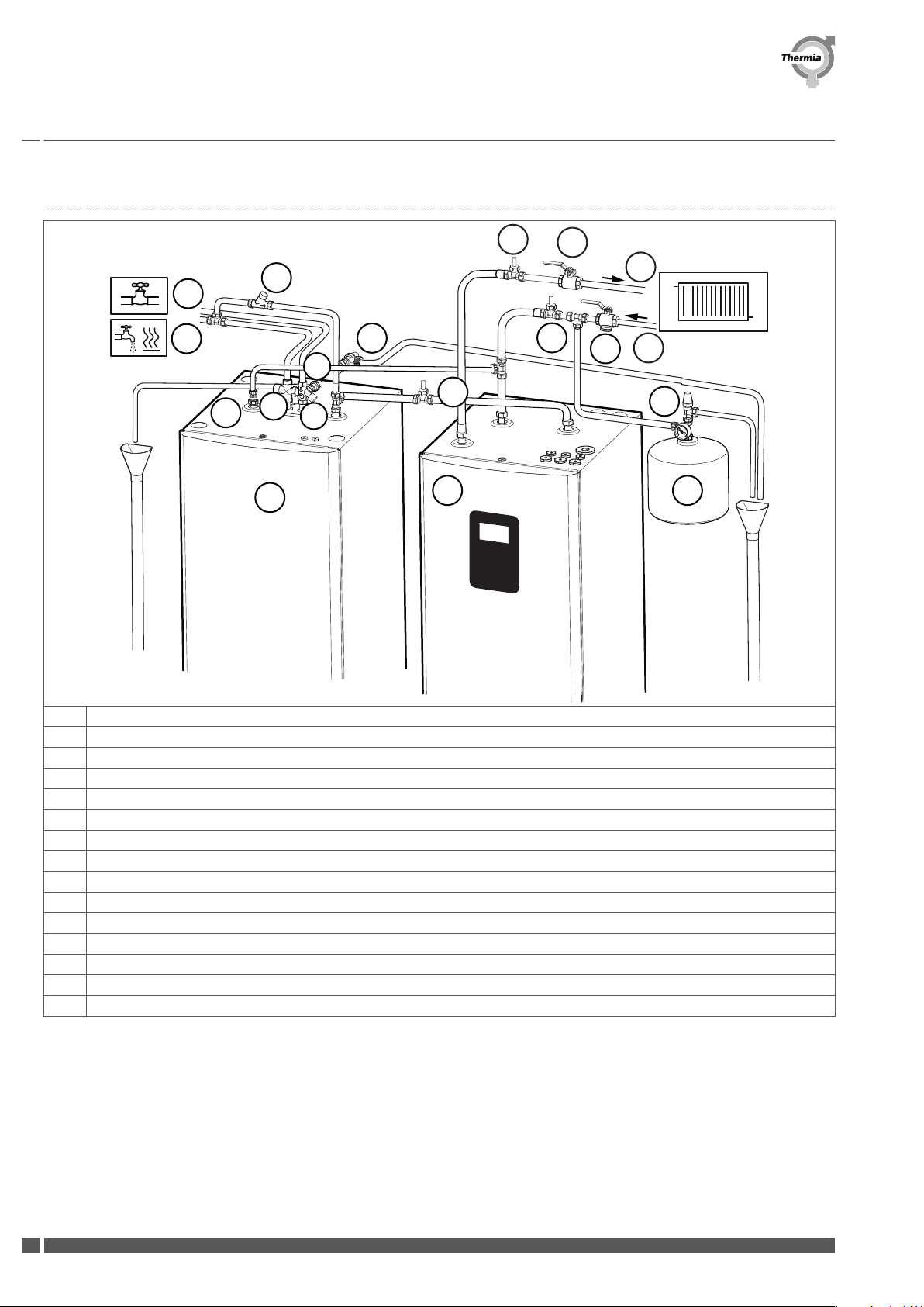
4.2 MBH 200, Diplomat Duo Inverter Mini ................................................ 12
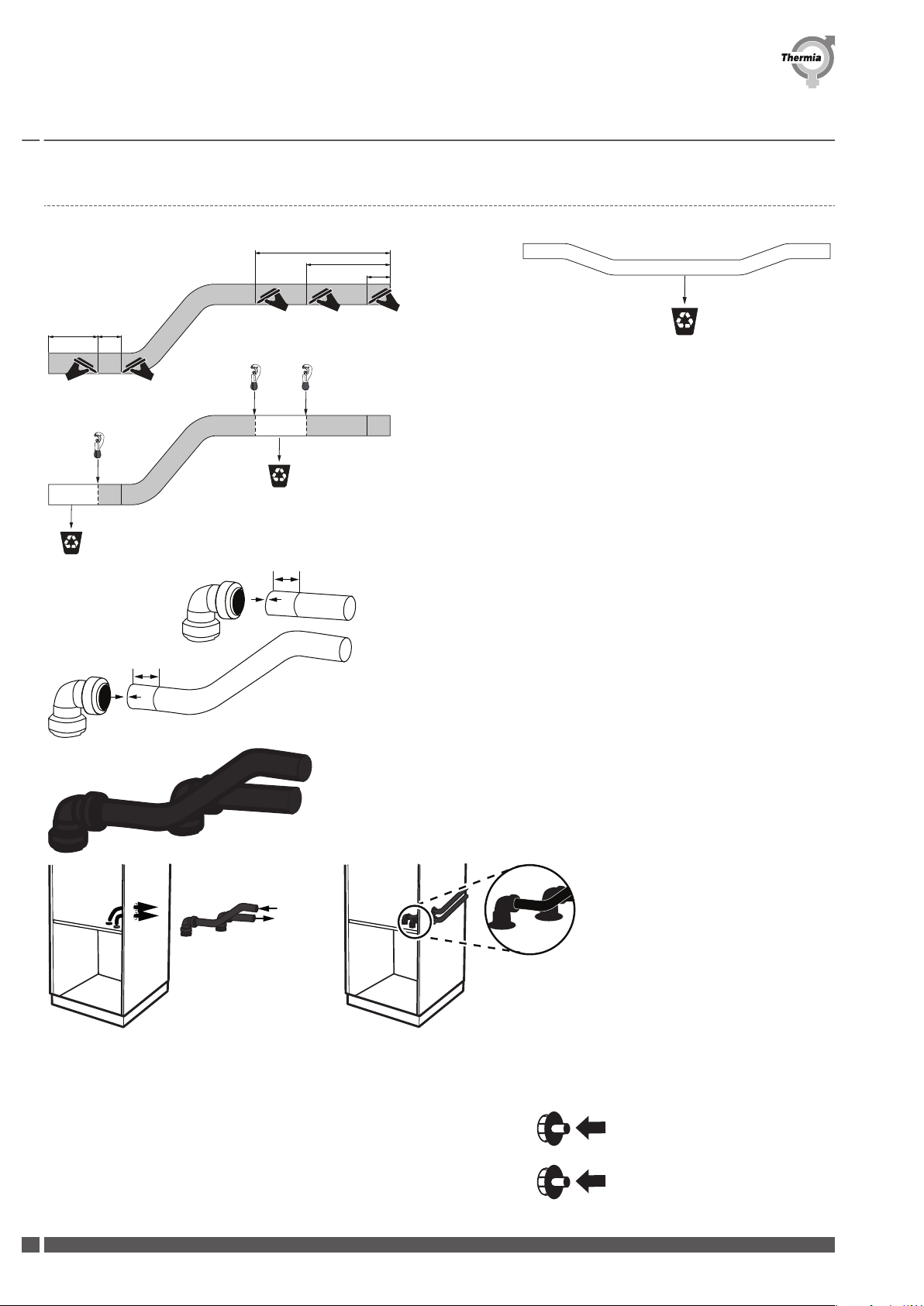
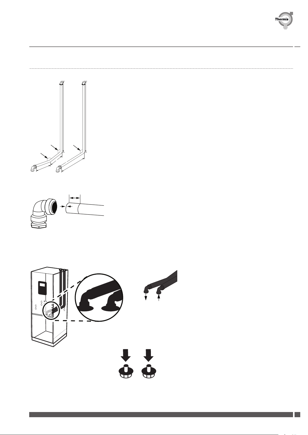
5 Connection, brine ................................................................ 13
5.1 Brine connection, alternatives ..................................................... 13
5.2 General information for brine connection ............................................. 14
5.3 Alternative 1 (left) ............................................................. 15
5.4 Alternative 2 (right) ............................................................ 16
5.5 Alternative 3 (top) ............................................................. 17
6 Sensors and power supply .......................................................... 18
6.1 Sensors and power supply ....................................................... 18
6.2 Outdoor sensor .............................................................. 18
6.3 Tap water, Diplomat Duo Inverter Mini ............................................... 18
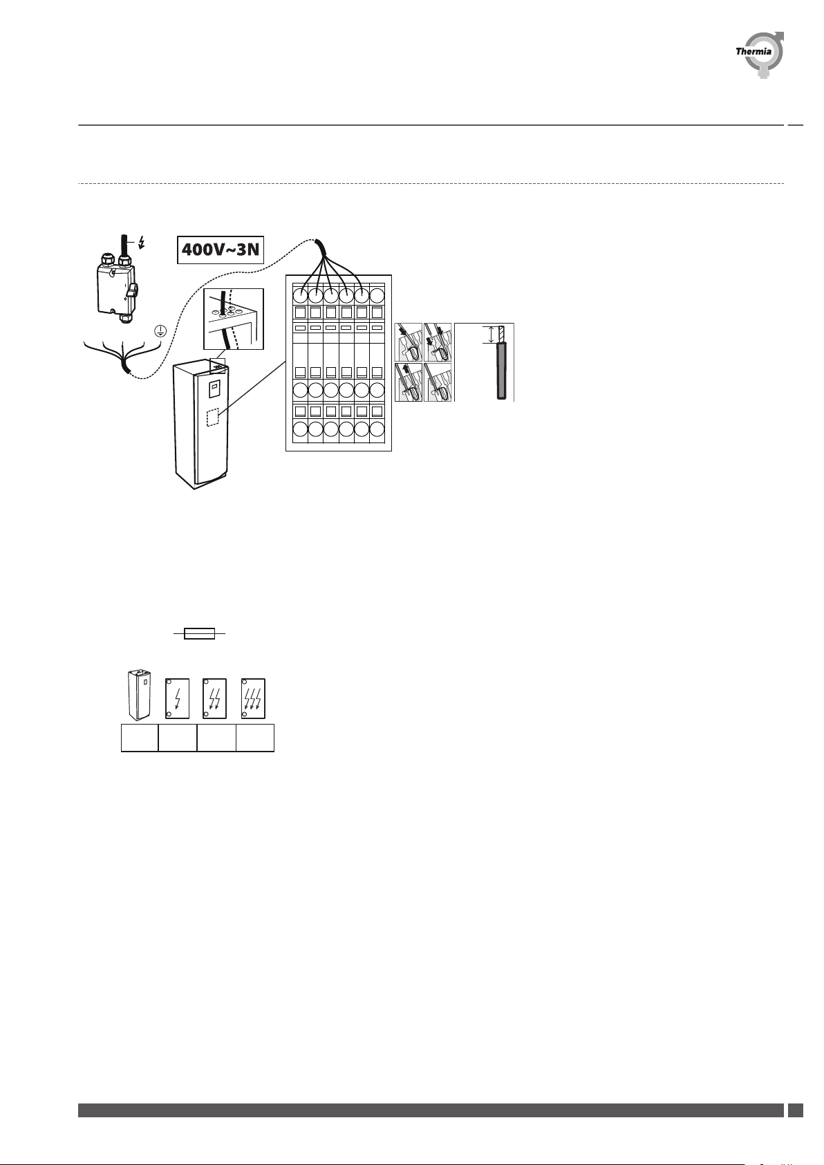
6.4 Power supply 400V version ....................................................... 19
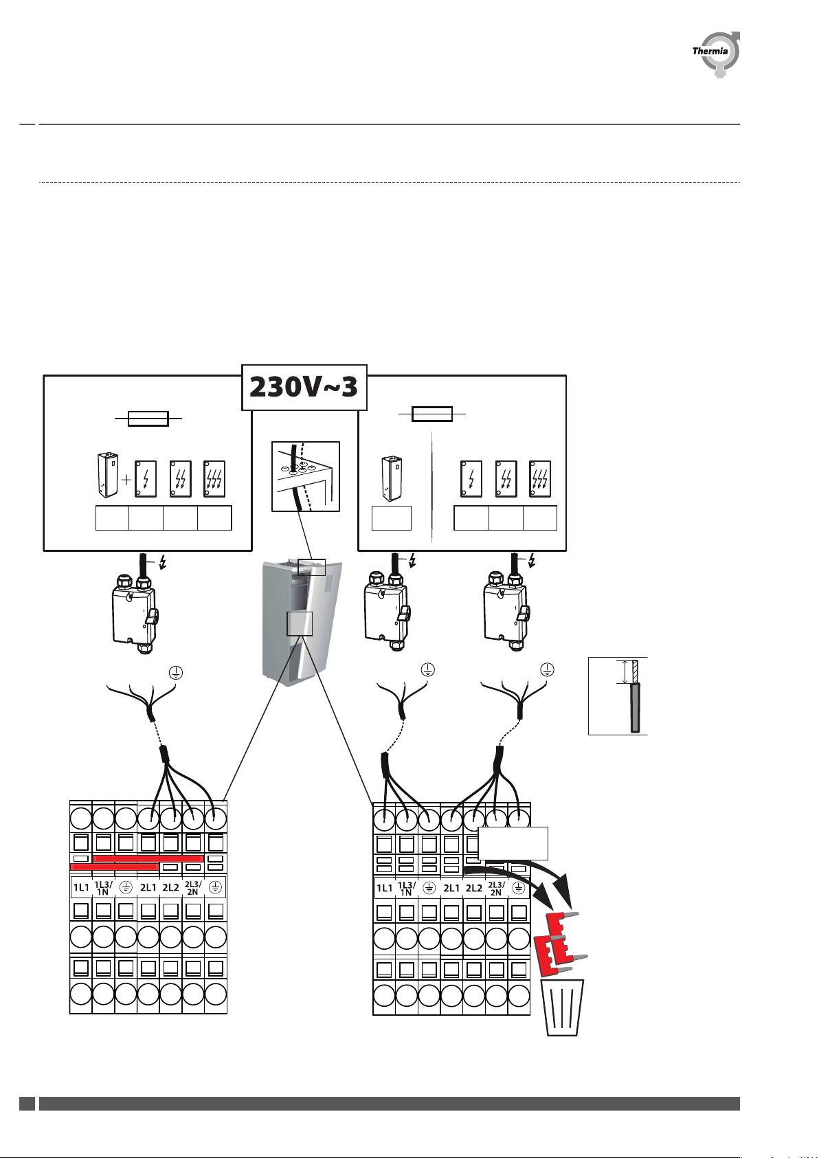
6.5 Power supply 230V heat pump version - Connection to three phase grid ......................... 20
6.6 Power Supply 230V heat pump version - Connection to single phase grid ......................... 21
7 Filling and bleeding .............................................................. 22
7.1 Filling and bleeding the brine circuit ................................................. 22
8 Commissioning .................................................................. 23
8.1 Activate manual test ........................................................... 23
8.2 Installer access ............................................................... 23
8.3 Online .................................................................... 27
8.4 Display symbol description ....................................................... 28
Installation Guide Diplomat Inverter Mini
Thermia AB INQG0102 3

1 About the document
1.1 About the dokument
This manual is a reduced version of the Installation guide and applies to installers with a prior experience in installing heat pumps. Indus-
trial standards and local regulations must always be followed.
Manuals with more extensive information and technical information can be found and downloaded here:
www.thermia.com under the tab Partner Login.
1.2 Important information
The instructions contain different warning symbols, which, together with text, indicate to the user that there are risks involved with ac-
tions to be taken.
The symbols are displayed to the left of the text and two different symbols are used to indicate the degree of danger:
Warning Risk of personal injury!
Indicates a possible danger that can lead to fatal or serious injury if
necessary measures are not taken.
Caution Risk of installation damage.
Indicates a possible hazard that can lead to item damage if necessary
measures are not taken.
1.3 Scrapping
Caution When the heat pump is to be scrapped the refrigerant must be extrac-
ted for disposal. Local rules and regulations related to the disposal of
refrigerant and heat pump must be followed.
Installation Guide Diplomat Inverter Mini
INQG0102 Thermia AB
4

1.4 Water quality
This heat pump and its components is developed to reliable and efficient work with water qualities in line with VDI 2035. In practice this
means that some general precautions should be taken:
As a heating system often contains small amounts of suspended solids (rust) and sludge products from calcium oxide, precaution should
be taken to ensure that the water in the heating system is as clean as possible to ensure long lasting performance and minimize the risk
of reliability issues. If magnetite can be expected in the heating system, cleaning of system and /or installation of magnetite filters
should always be considered. Any filters supplied with the heat pumps should always be installed. The dirt strainer should be fitted on
the return line from the heating system, as close to the heat pump as possible.
Heating system, hot water and brine circuit
Chemical and/or oil contamination shall always be avoided. In areas where there are exceptional water conditions with regards to hard
water, a softening filter may be necessary to use/install. The softening filter softens the water, cleans any impurities and prevents the
buildup of calcification.
1.5 Maximum length of collectors
In the tables below, calculated recommended maximum collector lengths to provide efficient running conditions are shown. The collec-
tor lengths may be applied independently on which heat source is used for the collector circuit (vertical/horizontal).
The lengths of the collectors are based on ethanol 30% at 0°C. (PEM40)
Diplomat Inverter Mini Diplomat Duo Inverter Mini Calculated maximum length of collectors (m) Floor
heating 35°C
Size (kW) ΔT=3K 1 collector 2 collectors
7 675 >1000
6 850 >1000
4 >1000 >1000
Diplomat Inverter Mini Diplomat Duo Inverter Mini Calculated maximum length of collectors (m)
Radiator heating 55°C (and/or hot water production)
Size (kW) ΔT=3K 1 collector 2 collectors
7 >1000 >1000
6 >1000 >1000
4 >1000 >1000
Installation Guide Diplomat Inverter Mini
Thermia AB INQG0102 5

1.6 Overview image
3a
▪Hot water
▪Heating system
▪Power
▪Brine
Installation Guide Diplomat Inverter Mini
INQG0102 Thermia AB
6

2 Heat pump data, dimensions and connections
2.1 Diplomat Inverter Mini
1864 (±10)
1770
455
598
703
40 ±10
686
86
726
617
75
118 379
498
1
2
4
67
8
5
3
1 Brine in, 28 mm
2 Brine out, 28 mm
3Heating system supply pipe, 28 mm
4 Heating system return pipe, 28 mm
5 Connection for bleed valve, 28 mm
6 Hot water line, 22 mm
7 Cold water line, 22 mm
8 Lead-in for supply, sensor and communication cables
The brine lines (1) and (2) can be connected on either the
left or right-hand sides or to the two knock out holes on the top.
2.2 Diplomat Duo Inverter Mini
455
598
40 ±10
1450 (±10)
1360
379
686
701
75
726
118
1
2
498
61785
4
5
36
1 Brine in, 28 mm
2 Brine out, 28 mm
3Heating system supply pipe, 28 mm
4 Heating system return pipe, 28 mm
5 Heating system supply pipe, 28 mm
6 Lead-in for supply, sensor and communication cables
The brine lines (1) and (2) can be connected on either the
left or right-hand side or to the two knock out holes on the top.
Installation Guide Diplomat Inverter Mini
Thermia AB INQG0102 7

3 Transportation, space requirement and Recommended location
3.1 Transportation
The heat pump must not be transported lying down!
Max 45
Maximum tilt 45 °
Diplomat Inverter Mini Diplomat Duo Inverter Mini
169kg!
127kg!
Installation Guide Diplomat Inverter Mini
INQG0102 Thermia AB
8

3.2 Space requirement and recommended location
Avoid placing the heat pump in a corner or near a bedroom. The surrounding
walls can amplify the sound from the heat pump.
1930 mm
1550 mm
0°C
OK
40°C
300 mm
300 mm
300 mm
10 mm
600 mm
x4
1
2
3
Adjust the heat pump using the adjustable feet so that it is horizontal on the
ground.
Installation Guide Diplomat Inverter Mini
Thermia AB INQG0102 9

When the heat pump is in position, remove the transport safety. (If the heat
pump should be moved further, put back the transport safety screw.)
The heat pump should be placed on a stable floor with a floor well (so any condensation may drain from the condensation hole in the
bottom of the heat pump), preferably a concrete floor. When placed on a wooden floor, the floor should be reinforced to hold the
weight of the heat pump, including a filled water heater. Consider that condensation water may drip from the drain hole, so take the
necessary steps to protect the floor.
Installation Guide Diplomat Inverter Mini
INQG0102 Thermia AB
10

4 Heating connections
4.1 Diplomat Inverter Mini
85
85
86
85
1
113
91
12
13
80
81
87
11
10
75
1 Heat pump
10 Heating system supply pipe
11 Heating system return pipe
12 Cold water line
13 Hot water line
75 Mixer valve hot water, with exchange valve
80 Shut-off valve
81 Filling valve
85 Venting valve
86 Safety valve (Max 3 bar, heat pump), recommended: 1,5 bar
87 Safety valve (9 bar, hot water)
91 Dirt strainer with shut-off valve, DN 25
113 Expansion vessel
Make sure that a free flow is always possible on the heating circuit. Very small water volumes or stop in the heating circuit may cause
operational disturbances.
Installation Guide Diplomat Inverter Mini
Thermia AB INQG0102 11

4.2 MBH 200, Diplomat Duo Inverter Mini
118
113
86
91
13
12
85
85
18 1
81
11
10
88
85 80
87
85
75
1 Heat pump
10 Heating system supply pipe
11 Heating system return pipe
12 Cold water line
13 Hot water line
18 Coil tank
75 Mixer valve hot water, with exchange valve
80 Shut-off valve
81 Filling valve
85 Venting valve
86 Safety valve (Max 3 bar, heat pump), recommended: 1,5 bar
87 Safety valve (9 bar, hot water)
88 Valve pipe (cold water)
91 Dirt strainer with shut-off valve, DN 25
113 Expansion vessel
Make sure that a free flow is always possible on the heating circuit. Very small water volumes or stop in the heating circuit may cause
operational disturbances.
Installation Guide Diplomat Inverter Mini
INQG0102 Thermia AB
12

5 Connection, brine
5.1 Brine connection, alternatives
1. Left knock-out
2. Right knock-out
3. Top knock-out
1
2
3
Equipment set-up for installing
Filler cock
Installation Guide Diplomat Inverter Mini
Thermia AB INQG0102 13

5.2 General information for brine connection
The quick couplings included are tool-free and pressed in place. The coupling locks automatically with resilient plastic ring. Before
mounting, check that there are no sharp edges or irregularities on the pipe that could damage the plastic ring in the couplings and
cause leakage. The clutch can be rotated after mounting on pipes.
32 mm 32 mm
Press the coupling on to the pipe and make sure it reaches the 32 mm mark. (When the coupling is correctly placed the pipe will be
visible at the curve of the coupling.)
To disassemble:
1. Push the plastic ring
2. Pull the pieces apart
1
2
Insulate the brine pipe and prepare with the insulation tape before installing the pipe in the heat pump. Loosen the tape from the pro-
tective film in partly, and place it behind the clutch when mounted on the pipe. This makes it easier to complete the insulation when the
tube is in place in the heat pump.
In order to access the brine connections, the metal plate to the electrical cabinet must be removed.
Installation Guide Diplomat Inverter Mini
INQG0102 Thermia AB
14

Remove knock-out holes to the left, right
or on top.
5.3 Alternative 1 (left)
For connection in to the left hand side "knockout holes".
1, Press the quick couplings (delivered with the heat pump) on to the pipes according to the picture . Make sure the coupling reach the
32 mm mark.
32 mm
32 mm
2, Insulate before mounting the pipes.
3, Install the insulated pipes from the inside of the heat pump and out. Pay attention to which one of the pipes are brine in and brine
out. (See picture below.)
4, Press the pipes on to the connections in the heat pump. (The pipe connections are located behind the electrical cabinet in the heat
pump, remove the metal plate.)Isolate with insulation tape so that it is partially seated against the plate.
IN
OUT
5, Fit the rubber sleeves into the knockout holes.
Installation Guide Diplomat Inverter Mini
Thermia AB INQG0102 15

5.4 Alternative 2 (right)
For connection in to the right hand side "knockout holes".
184
67 32
114
32
32 mm
32 mm
1, Press the quick clutches (delivered with the heat pump) on to the pipes . Make sure the
clutch reach the 32 mm mark.
2, Insulate before mounting the pipes.
Brine IN
Brin OUT
3, Press the pipes on to the connections in the heat pump. (See picture below.) Install the insulated pipes from the inside of the heat
pump and out. Pay attention to which one of the pipes are brine in and brine out.(The pipe connections are located behind the electri-
cal cabinet in the heat pump, remove the metal plate.)Isolate with insulation tape so that it is partially seated against the plate.
4, Fit the rubber sleeves into the knockout
holes.
Installation Guide Diplomat Inverter Mini
INQG0102 Thermia AB
16

5.5 Alternative 3 (top)
For connection in the top "knockout holes". For this option, pipes are not included in the delivery.
min
1140 mm
min
1140 mm
420 mm
232 mm
Duo: 731mm Duo: 731mm
251 mm
160°
90° 90°
Make the pipes according to the dimensions of the picture! Suitable choice is CU 28 mm intended for brine pipes.
32 mm
2, Insulate before mounting the pipes.
3, Press the pipes on to the connections in the heat pump. (See picture below.) Install the insulated pipes from the inside of the heat
pump and out. Pay attention to which one of the pipes are brine in and brine out.(The pipe connections are located behind the electri-
cal cabinet in the heat pump, remove the metal plate.) Isolate with insulation tape so that it is partially seated against the plate.
Brine IN Brine OUT
4, Fit the rubber sleeves into the knockout
holes.
Installation Guide Diplomat Inverter Mini
Thermia AB INQG0102 17

6 Sensors and power supply
6.1 Sensors and power supply
Warning Electrical voltage!
The connection terminals are powered and can cause life hazards due
to electrical shock. All power supplies must be disconnected before
electrical installation can commence.
6.2 Outdoor sensor
<50 m = 0.75 mm
50-120 m = 1.5 mm
2/3x H
H
220nMBB2
M404-CBM-SLM
4n7MBK4 4n7MBK4
HIGHVOLTAGE
HIGHVOLTAGE
HIGHVOLTAGE
1. Improper
placement
2. Proper place-
ment
6.3 Tap water, Diplomat Duo Inverter Mini
Top
Low/Mid
220nMBB2
M404-CBM-SLM
4n7MBK4 4n7MBK4
HIGHVOLTAGE
HIGHVOLTAGE
HIGHVOLTAGE
Factory-fitted with built-in water tank.
Installation Guide Diplomat Inverter Mini
INQG0102 Thermia AB
18

6.4 Power supply 400V version
If the heat pump is connected to ground fault switch RCDs, it should be connected to a separate type B.
L1 L2
N
L3
L1
PE
PE
L2
L3 N
12
3
4OK
12mm
▪L1, L2: Internal immersion heater, control and circulation pump
▪L3: Inverter, compressor
Fuse size
400V, ~3N, 50 Hz
FUSE
C-CURVE
6kW
13A 13A 13A 16A1,5-7kW
+
2kW
4kW
Minimum recommended fuse size.
Maximum operating current of compressor: 12 A at 230V (nominal)
The internal immersion heater limit in the heat pump control and may be permitted in different steps with / without compressor.-
▪Step 1: 2kW
▪Step 2: 4kW
▪Step 3: 6kW
Installation Guide Diplomat Inverter Mini
Thermia AB INQG0102 19

6.5 Power supply 230V heat pump version - Connection to three phase grid
Connection possibilities, 230V~3 three phase grids with:
1. One common feeding cable to supply both compressor and immersion heater. This is default from factory. (Inbuilt auxiliary heater
power = 2/4/6 kW.)
or
2. Two separate feeding cables to supply compressor and immersion heater separately. (Inbuilt auxiliary heater power = 2/4/6 kW.)
This alternative will reduce required fuse size and required inlet cable area but requires that the jumpers fitted in the terminals are re-
moved. (See connection picture). To remove jumpers, use a flat screw driver and remove the 2 red jumpers fitted on the terminal block
before connecting heat pump to the grid.
Compressor Auxiliary heater
2kW 4kW 6kW 2kW 4kW 6kW1,5-7kW
1,5-7kW 16A 25A 32A 40A 16A 10A 16A 25A
2L1 2L2 1L1 2L1 2L2
2N
2L3/ 1N
1L3/ 2N
2L3/
FUSE
C-CURVE
FUSE
C-CURVE
2/4/6kW Auxiliary heater 2/4/6kW Auxiliary heater
(Compressor +
Auxiliary heater)
Remove
jumpers!
One feeding (230V~3) Two feedings (230V~3)
18mm
( The 230V heat pump versions must never be connected to 400V grids.)
Installation Guide Diplomat Inverter Mini
INQG0102 Thermia AB
20
This manual suits for next models
2
Table of contents