Select Switch (SW501)
Dip Switch 1: ON - Torque Mode - The drive will control the torque (current) of the motor. This is used
Dip Switch 1: ON - in tensioning applicaons.
Dip Switch 1: OFF - Speed Mode - The drive will control the speed (voltage) or the motor. This is used
Dip Switch 1: OFF - in variable speed applicaons.
Dip Switch 2: ON - WigWag Mode - The potenometer or analog signal determines both motor speed
Dip Switch 1: ON - WigWag Mode - and direcon. The direcon switch will sll come into effect.
Dip Switch 1: OFF - Pot/Switch Mode - The potenometer or analog signal (0 - 5 VDC, 0 - 10 VDC,
Dip Switch 1: OFF - Pot/Switch Mode - 4-20 mA) determines the motor speed while the direcon
Dip Switch 1: OFF - Pot/Switch Mode - switch determines the direcon. If using a bidireconal
Dip Switch 1: OFF - Pot/Switch Mode - analog signal (0 to ± 10 VDC), the polarity of the signal
Dip Switch 1: OFF - Pot/Switch Mode - determines the direcon (ie -10 VDC is full speed reverse,
Dip Switch 1: OFF - Pot/Switch Mode - 0 VDC is zero speed, 10 VDC is full speed forward). The direcon
Dip Switch 1: OFF - Pot/Switch Mode - switch will sll come into effect even with a bidireconal signal.
Dip Switch 3: ON - Brake Mode - Opening the ENABLE switch will regeneravely brake the motor to
zero speed without applying the decel ramp. At zero speed, the drive
will apply holding torque.
Dip Switch 1: OFF - Enable Mode - Opening the ENABLE switch will coast the motor to a stop. The drive
cannot provide holding torque at zero speed because it’s disabled.
SELECT SWITCHES
JUMPERS
Startup
1
2
3
4
7
8
5
6
9
10
1
2
3
4
7
8
5
6
9
10
1
2
3
4
7
8
5
6
9
10
STARTUP
- Verify that no foreign conducve material is present on the printed circuit board.
- Ensure that all switches and jumpers are properly set.
1. Turn the speed adjust potenometer full counterclockwise (CCW) or set the analog input voltage
1. or current signal to minimum.
2. Apply AC line voltage.
3. Close the enable switch and verify that the green Power LED (IL1) if flashing.
4. Slowly advance the speed adjust potenometer clockwise (CW) or increase the analog input voltage
3. or current signal. The motor slowly accelerates as the potenometer is turned CW or as the analog
3. input voltage or current signal is increased. Connue unl the desired speed is reached.
5. Remove AC line voltage from the drive to coast the motor to a stop.
0-5 VDC or Potenometer 0 to ± 10 VDC 4-20 mA
Jumper Pins 1&2 and 7&8 Jumper Pins 3&5 and 7&8 Jumper Pins 5&6 and 9&10
Potenometer
0 - 5 VDC
0 - 10 VDC
4 - 20 mA
Full Speed
Reverse
Full CCW
0 VDC
0 VDC
4 mA
Zero
Speed
12 o’clock
2.5 VDC
5 VDC
12 mA
Full Speed
Forward
Full CW
5 VDC
10 VDC
20 mA
Calibration
CALIBRATION INSTRUCTIONS ARE ASSUMING THAT THE DRIVE IS SET UP FOR SPEED MODE AND
POT/SWITCH MODE. IF USING TORQUE MODE OR WIGWAG MODE, PLEASE REFER TO THE USER’S
MANUAL.
Zero Adjust (P1 / ZERO ADJ): The ZERO ADJ seng adjusts out any non-linearies in the logic circuit that
might arise from component tolerances. This factory calibrated and should not need any adjustment.
Minimum Speed (P2 / MIN SPEED): The MIN SPEED seng determines the minimum motor speed
when the speed adjust potenometer is set for minimum speed. It is factory set for zero speed. To
calibrate the MIN SPEED:
1. Set the MIN SPEED trim pot full CCW.
2. Set the speed adjust potenometer or input voltage or current signal for minimum speed.
3. Adjust the MIN SPEED trim pot unl the desired minimum speed is reached or is just at the
3. threshold of rotaon.
Maximum Forward Speed (P3 / MAX FWD SPEED): The MAX FWD SPEED seng determines the
maximum motor speed in the forward direcon when the speed adjust potenometer or input voltage
or current signal is set for maximum speed. It is factory set for maximum motor rated speed. To
calibrate the MAX FWD SPEED:
1. Set the MAX FWD SPEED trim pot full CCW.
2. Set the speed adjust potenometer or input voltage or current signal for maximum forward
speed.
3. Adjust the MAX FWD SPEED trim pot unl the desired maximum forward speed is reached.
Maximum Reverse Speed (P4 / MAX REV SPEED): The MAX REV SPEED seng determines the
maximum motor speed in the reverse direcon when the speed adjust potenometer or input voltage
or current signal is set for maximum speed. It is factory set for maximum motor rated speed. To
calibrate the MAX REV SPEED:
1. Set the MAX REV SPEED trim pot full CCW.
2. Set the speed adjust potenometer or input voltage or current signal for maximum reverse
speed.
3. Adjust the MAX REV SPEED trim pot unl the desired maximum reverse speed is reached.
Check the ZERO ADJ, MIN SPEED, MAX FWD SPEED and MAX REV SPEED adjustments aer recalibrang
to verify that the motor runs at the desired minimum and maximum speeds.
Acceleraon (P5 / ACCEL TIME): The ACCEL TIME seng determines the me the motor takes to ramp
to a higher speed regardless of direcon. To calibrate the ACCEL TIME, turn the ACCEL TIME trim pot
CW to increase the forward acceleraon me and CCW to decrease the forward acceleraon me.
Deceleraon (P6 / DECEL TIME): The DECEL TIME seng determines the me the motor takes to ramp
to a lower speed regardless of direcon. To calibrate the DECEL TIME, turn the DECEL TIME trim pot
CW to increase the forward deceleraon me and CCW to decrease the forward deceleraon me.
Forward Torque (P7 / MOTOR CUR LIM): The MOTOR CUR LIM seng determines the maximum
torque for accelerang and driving the motor in the forward or reverse direcons. To calibrate the
MOTOR CUR LIM:
1. With the power disconnected from the drive, connect a DC ammeter in series with the
1. armature.
2. Set the MOTOR CUR LIM trim pot to minimum (full CCW).
3. Set the speed adjust potenometer (full CW) or input voltage or current signal to maximum
6. forward speed (full CW).
4. Carefully lock the motor armature. Be sure that the motor is firmly mounted.
5. Apply power source. The motor should be stopped.
6. Slowly adjust the MOTOR CUR LIM trim pot CW unl the armature current is 150% of motor
6. rated armature current.
7. Turn the speed adjust potenometer to minimum speed (full CCW).
8. Remove power source.
9. Remove the stall from the motor.
10. Remove the ammeter in series with the motor armature if it is no longer needed.
Reverse Torque (P8 / REGEN CUR LIM): The REGEN CUR LIM seng determines the maximum torque
for decelerang the motor and resisng an overhauling load in the forward and reverse direcons.
Turn the REGEN CUR LIM trim pot CW to increase the regen current limit and CCW to decrease the
regen current limit.
IR Compensaon (P9 / IR COMP): The IR COMP seng determines the degree to which motor speed is
held constant as the motor load changes. It is factory set for opmum motor regulaon. To calibrate
the IR COMP:
1. Set the IR COMP trim pot full CCW.
2. Increase the speed adjust potenometer or input voltage or current signal unl the motor runs
2. at midspeed without load. A handheld tachometer may be used to measure motor speed.
3. Load the motor armature to its full load armature current rang. The motor should slow down.
4. While keeping the load on the motor, rotate the IR COMP trim pot unl the motor runs at the
4. speed measured in step 2. If the motor oscillates (overcompensaon), the IR COMP trim pot
4. may be set too high (CW). Turn the IR COMP trim pot CCW to stabilize the motor.
5. Unload the motor.
LEDs
POWER
LED STATUS
LED
Power (IL1): Green LED is solid when AC line voltage is applied to the drive, but the drive is disabled. It
flashes whenever AC line voltage is applied to the drive and the drive is enabled.
Status (IL2): Red LED is solid when in current limit or flashes following fault code:
2 Flashes: Undervoltage - Internal DC BUS voltage dropped too low.
3 Flashes: Overvoltage - Internal DC BUS voltage rose too high.
4 Flashes: Current Limit or Short Circuit - The drive is in current limit or has detected a short across the
motor.
5 Flashes: Overtemperature Shut Down - Drive’s temperature has reached crical temperature.
6 Flashes: Overtemperature Warning - Drive’s temperature is approaching crical temperature.
Maximum motor current is being reduced gradually as the drive’s temperature rises.
BT
L1 L2 L2-DBL U/A2 V/A1 W
IL2
IL1
J502
SW501
J503
TB502
Operation
S3
S2
S1
RUN
DECEL TO
MIN SPEED
10K OHM
SPEED ADJUST
POTENTIOMETER
CW
Decelerate to Minimum or Zero Speed
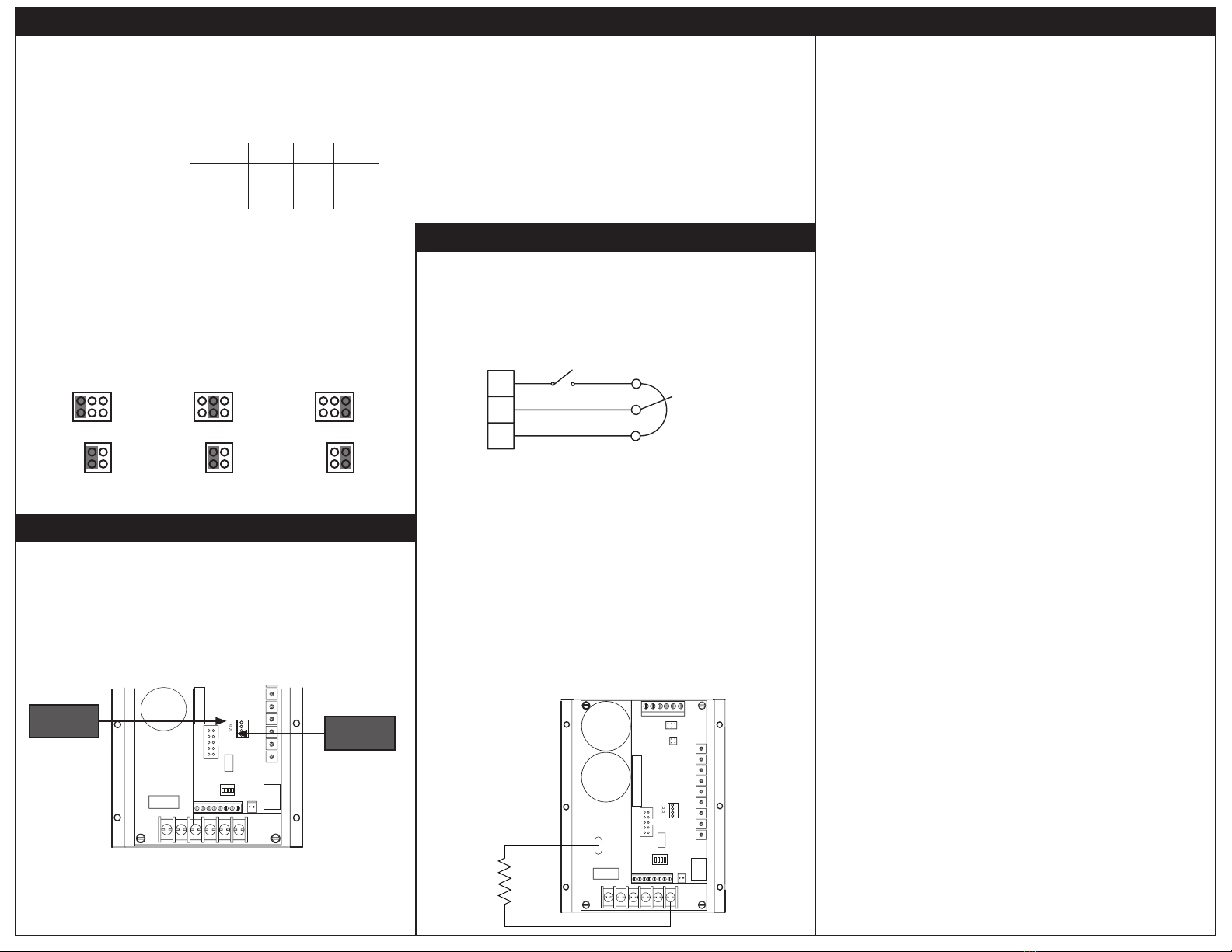
The switch shown below may be used to decelerate a motor to a minimum speed. Opening the switch
between S3 and the potenometer decelerates the motor from set speed to a minimum speed
determined by the MIN SPEED trim pot seng. If the MIN SPEED trim pot is set full CCW, the motor
decelerates to zero speed when the switch is opened. The DECEL TIME trim pot seng determines the
rate at which the drive decelerates when travling in the forward direcon. By opening the switch, the
motor accelerates to set speed at a rate determined by the ACCEL TIME trim pot seng if accelerang
in the forward direcon.
DECELERATING & STOPPING
PWM drives are limited in their regnerave capability. The regenerave energy is returned into the
drive’s bus capacitor. When this capacitor is full, the drive can no longer regen unl the capacitor begins
to empty. During these periods, the motor actually coasts. While the regen/coast periods are frequent
enough that the user may not see the transions, it does result in a longer deceleraon me.
The soluon is a brake resistor. When the capacitor is full, the drive will divert the regen energy through
through the resistor. For the regenerave brake resistor, use a 40 wa minimum, high power, wire-
wound resistor. Sizing the regenerave brake resistor depends on load inera, motor voltage, and
braking me. Use a lower-value, higher-waage dynamic brake resistor to stop a motor more rapidly.
Brake resistor values must not be less than 40 ohms.
Please note that applicaons with light regenerave loads may not require the
use of a regenerave brake resistor.
If using a regenerave brake resistor, connect the resistor across terminals W and +BUS.
REGENERATIVE BRAKE RESISTOR
205B
T
L1 L2/230 L2/115 U V W
IL2
IL1
J502
TB501
SW501
J503
TB502
+BUS
REGENERATIVE
BRAKE
RESISTOR
31 5
4
7 9
8 10
2 6
QSG-0067 rev 0
Copyright 2013 by American Control Electronics® - All rights reserved. No part of this document may be
reproduced or retransmied in any form without wrien permission from American Control Electronics®.
The informaon and technical data in this document are subject to change without noce. American
Control Electronics® makes no warranty of any kind with respect to this material, including, but not
limited to, the implied warranes of its merchantability and fitness for a given purpose. American
Control Electronics® assumes no responsibility for any errors that may appear in this document
and makes no commitment to update or to keep current the informaon in this document.


