B&C DE Series User manual
Dryer
DE Series Installation and Operation Manual
March 17, 2014
Revision 1.7

Contents
1 Important Safety Information 1
1.1 FORYOURSAFETY-CAUTION! ............................. 1
2 Important Instructions 3
2.1 BeforeAttemptingRepairs.................................. 3
2.2 PartsOrderingInformation ................................. 4
2.2.1 NameplateLocation ................................. 4
2.3 KeySymbols.......................................... 5
2.4 SafetyInformation ...................................... 6
2.5 Installation and Operational Safety Instructions . . . . . . . . . . . . . . . . . . . . . 6
3 Installation 8
3.1 ReceivingInspection ..................................... 8
3.2 ElectricalInstallation ..................................... 14
3.3 GasConnection ........................................ 15
3.3.1 GasSupplyLine ................................... 15
3.3.2 Gas Supply Connection Requirements . . . . . . . . . . . . . . . . . . . . . . . 15
3.4 SteamConnection....................................... 16
3.5 SteamDamper......................................... 17
3.5.1 SteamDamperOperation .............................. 18
3.5.2 Steam Damper Air Piston Adjustment . . . . . . . . . . . . . . . . . . . . . . . 18
3.6 ExhaustRequirements .................................... 18
3.7 PlumbingRequirements ................................... 20
3.8 EnclosureRequirements ................................... 21
i

3.9 FreshAirRequirements ................................... 23
4 Operation 25
4.1 HeatCircuitOperationTest ................................. 26
4.2 OperatingInstructions .................................... 27
5 Troubleshooting 29
5.1 NoHeat ............................................ 29
5.2 MachineWillNotStart.................................... 29
6 Maintenance 34
6.1 Warranty............................................ 34
6.2 RoutineMaintenance..................................... 35
6.2.1 Cleaning........................................ 35
6.2.2 MaintenanceIntervals ................................ 35
6.2.3 Adjustments...................................... 36
6.2.4 Lubrication ...................................... 37
6.3 Service&Parts ........................................ 37
6.3.1 Service......................................... 37
6.3.2 Parts .......................................... 37
7 Decommisioning 38
8 Appendix 39
8.1 GasConversionTechnique.................................. 39
8.1.1 Converting Gas Types, DE-30 . . . . . . . . . . . . . . . . . . . . . . . . . . . . 39
8.1.2 Converting Gas Types, DE-50 and Larger . . . . . . . . . . . . . . . . . . . . . 40
8.1.3 RegulatorAdjustment ................................ 41
ii

Chapter 1
Important Safety Information
1.1 FOR YOUR SAFETY - CAUTION!
WARNING: For your safety the information in this manual must be followed to minimize the
risk of fire or explosion or to prevent property damage, personal injury or death.
•Do not store or use gasoline or other flammable vapors and liquids in the vicinity of this or
any other appliance.
•WHAT TO DO IF YOU SMELL GAS:
–Do not try to light any appliance
–Do not touch any electrical switch; do not use any phone in your building.
–Clear the room, building or area of all occupants.
–Immediately call your gas supplier from a neighbor’s phone. Follow the gas supplier’s
instructions.
–If you cannot reach your gas supplier, call the fire department.
•Installation and service must be performed by a qualified installer, service agency or the gas
supplier.
Contact your local gas supplier to obtain particular instructions in the event that a user smells
gas. Place this sheet and any other instructions obtained from your gas supplier in a prominent
location.
1

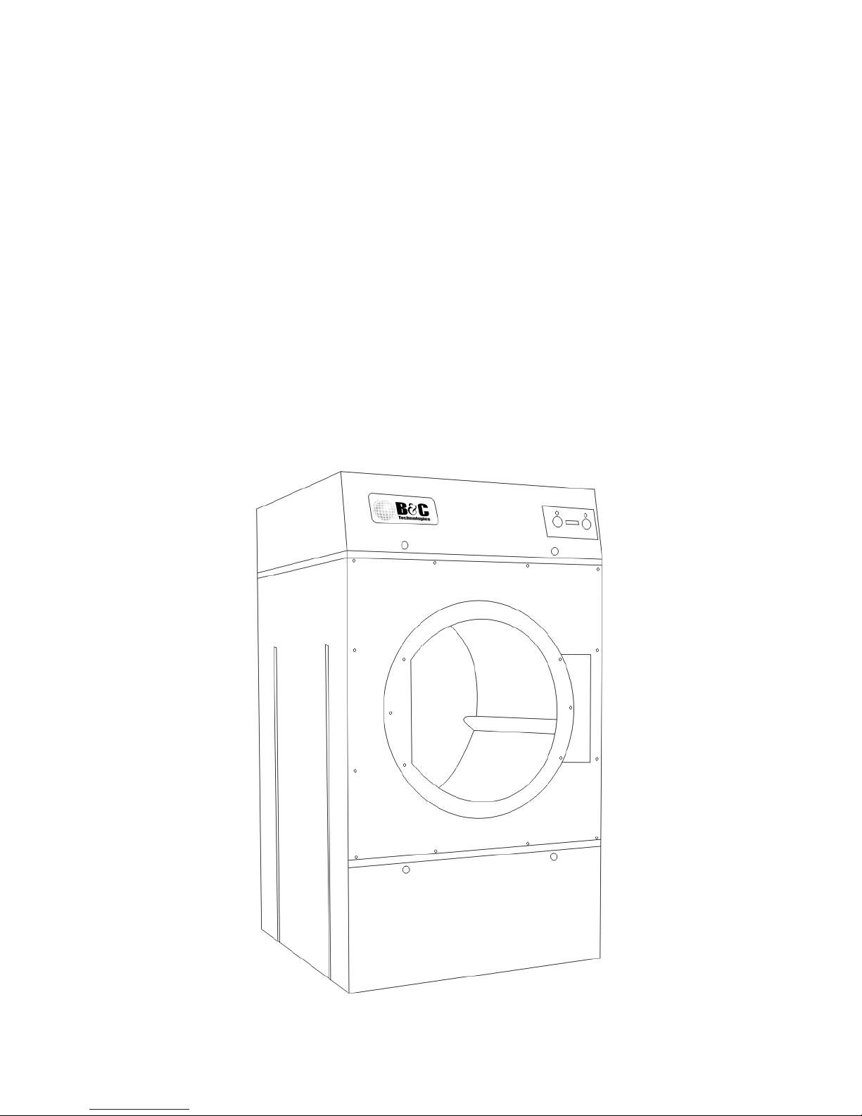
Figure 1.1: DE Product Family
2
Chapter 2
Important Instructions
2.1 Before Attempting Repairs
Moving parts can cause serious injury or death. Before attempting repairs, follow proper shut-
down procedures, remove power, and allow the machine to fully cool before commencement of
service.
Safety is of primary concern with any maintenance or repair operation. If you are in any way
unsure of how to proceed with a repair or adjustment, consult this manual, a qualified mainte-
nance technician, your local distributor, or the B&C Technologies Technical Service Department at
850-249-2222.
Only trained and experienced personnel should attempt maintenance or repair work on this equip-
ment. Follow all safety procedures including lock-out/tag-out procedures carefully. Ensure that
any loose fitting clothing or jewelry is tucked in or not worn to avoid being pulled into the ma-
chine. Remember, the machine has no brain - you must use your own.
Before attempting repairs, follow proper shutdown procedures, remove power, and allow the ma-
chine to fully cool before commencement of service.
Never attempt to clean or service any area of the machine without removing power at the main
disconnect and allowing time for the machine to cool completely.
3

Figure 2.1: Serial Decal
Read, follow, and obey these safety rules! The B&C Technologies Technical Service Department
is available to answer any questions you may have about the operation and servicing of your
machine. Please call with any questions or concerns about the operation of your machine.
2.2 Parts Ordering Information
If you require literature or spare parts, please contact your local distributor. If a local distributor
is unavailable, you may contact B&C Technologies directly at (850) 249-2222 for the name of your
nearest parts dealer.
For technical assistance in the United States, contact B&C Technologies:
(850) 249-2222 Phone
(850) 249-2226 FAX
www.bandctech.com
2.2.1 Nameplate Location
When contacting B&C Technologies about your equipment, please make note of the model and
serial number, located on the nameplate as shown in figure 2.1.
4
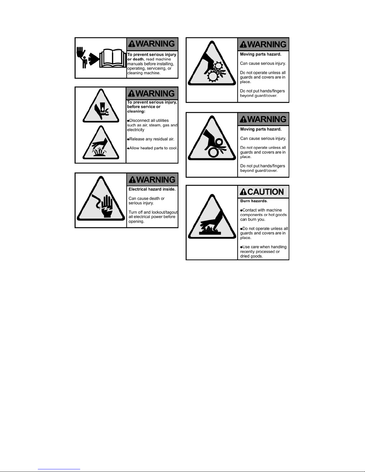
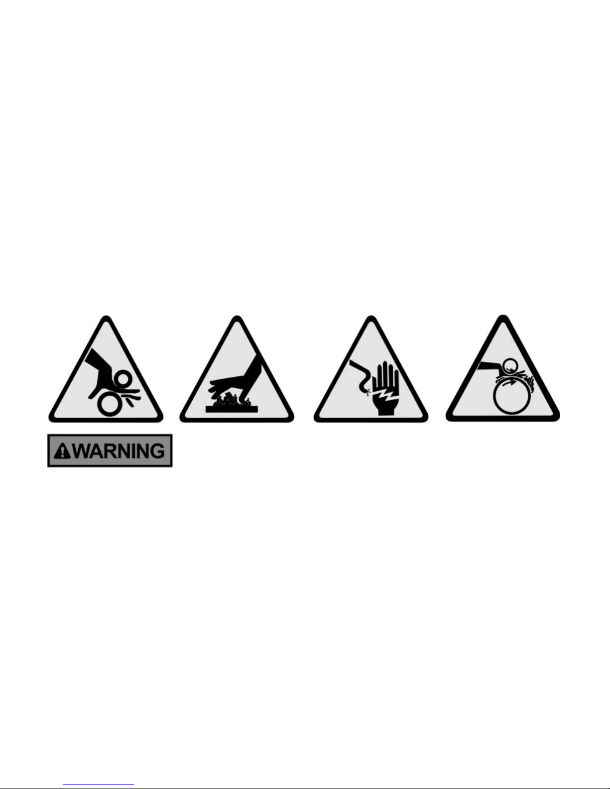
Figure 2.2: Key Symbols
2.3 Key Symbols
Anyone operating or servicing this machine must follow the safety rules in this manual. Partic-
ular attention must be paid to the DANGER, WARNING, and CAUTION blocks which appear
throughout the manual and shown in figures 2.2 on page 5 and 2.3 on page 6.
5

Figure 2.3: Key Symbols
2.4 Safety Information
Installation Notice: For personal safety and for proper operation, the machine must be grounded
in accordance with state and local codes and in the USA in accordance with the National Electric
Code, article 250-96. Elsewhere, the equipment should be grounded in accordance with ANSI/NFPA
70, or the Canadian Electrical Code, CSA C22.1. The ground connection must be to a proven earth
ground, not to conduit or water pipes.
Natural Gas or Liquid Propane Gas (LP Gas) heated equipment installation must comply with
state and local codes, and in the USA, in accordance with the National Fuel Gas Code. Elsewhere,
the equipment should comply with ANSI Z22.1, or CSA B149.
Provisions must be made for adequate make-up air and ventilation, and access for equipment
service and installation.
2.5 Installation and Operational Safety Instructions
1. Read all instructions prior to operating this equipment.
2. Ensure that the equipment is properly grounded before applying power and operation com-
mences.
3. Do not process goods that have been previously cleaned in, soaked in, or exposed to gasoline,
dry cleaning chemicals, or any other flammable or explosive materials, as they could catch
fire or explode without warning, even after being washed.
4. Do not allow children to play in or around or operate this equipment.
5. Check the operation of all safety interlocks at the start of every shift. If the interlocks do not
stop the equipment immediately, the machine must be removed from service. Notify your
immediate supervisor, and do not operate the machine.
6

6. Never attempt to service the machine while it is running. Never reach over, under, around, or
behind any safety device, or into any area near moving parts or hot surfaces without shutting
off power and allowing the machine to adequately cool.
7. Read, understand, and follow all safety instructions. Do not come close to moving parts and
hot surfaces. Do not wear loose clothing, jewelry, neckties, or any other garment that could
be come caught in the machine while operating or near the machine.
8. Only a qualified technician should attempt to service or repair the dryer.
9. Do not install the machine in an area where it could be exposed to water or weather.
10. Do not alter or tamper with the control system.
11. To reduce the risk of fire, do not process plastics or articles containing foam rubber or simi-
larly textured rubber-like materials.
12. Keep the area near the exhaust ducting clean and free of lint, dust, dirt or debris.
13. Keep the interior and exterior of the machine clean of lint, dirt, dust and debris. The inte-
rior of the machine, along with the exhaust ductwork should be periodically inspected and
cleaned to avoid potential fires (lint is highly flammable).
14. Improper installation, operation and maintenance of this machine can cause exposure to sub-
stances in the fuel or from combustion that can cause serious illness or death. The machine
must be exhausted to the outside.
15. Always disconnect the electrical service from the machine and allow it to cool before per-
forming service.
16. This machine must be installed according to the installation instructions. All exhaust, elec-
trical connections, and gas or steam connections must comply with state and local codes and
must be made by a licensed installer where required.
17. Remove articles from the dryer as soon as the drying cycle has completed. Articles left in the
dryer can create a fire hazzard.
7

Chapter 3
Installation
3.1 Receiving Inspection
Upon receipt of the equipment, visually inspect for shipping damage and note any damage with
the carrier before signing the shipping receipt, or advise the carrier of the damage as soon as it is
noted.
If damage is discovered, a written claim must be filed with the carrier as soon as possible.
Note: Warranty is VOID unless the equipment is installed according to instructions. The installa-
tion must comply with the minimum requirements listed in this manual. All national, state and
local codes must be followed including but not limited to gas, electrical, plumbing and HVAC.
Due to various requirements, statutory codes should be well understood before installation com-
mences.
Important: The dryer should be transported and handled in an upright position.
8

Figure 3.1: DE Gas General Specifications
9

Figure 3.2: DE-30 Utility Connections
10

Figure 3.3: DE-50/75 Utility Connections
11
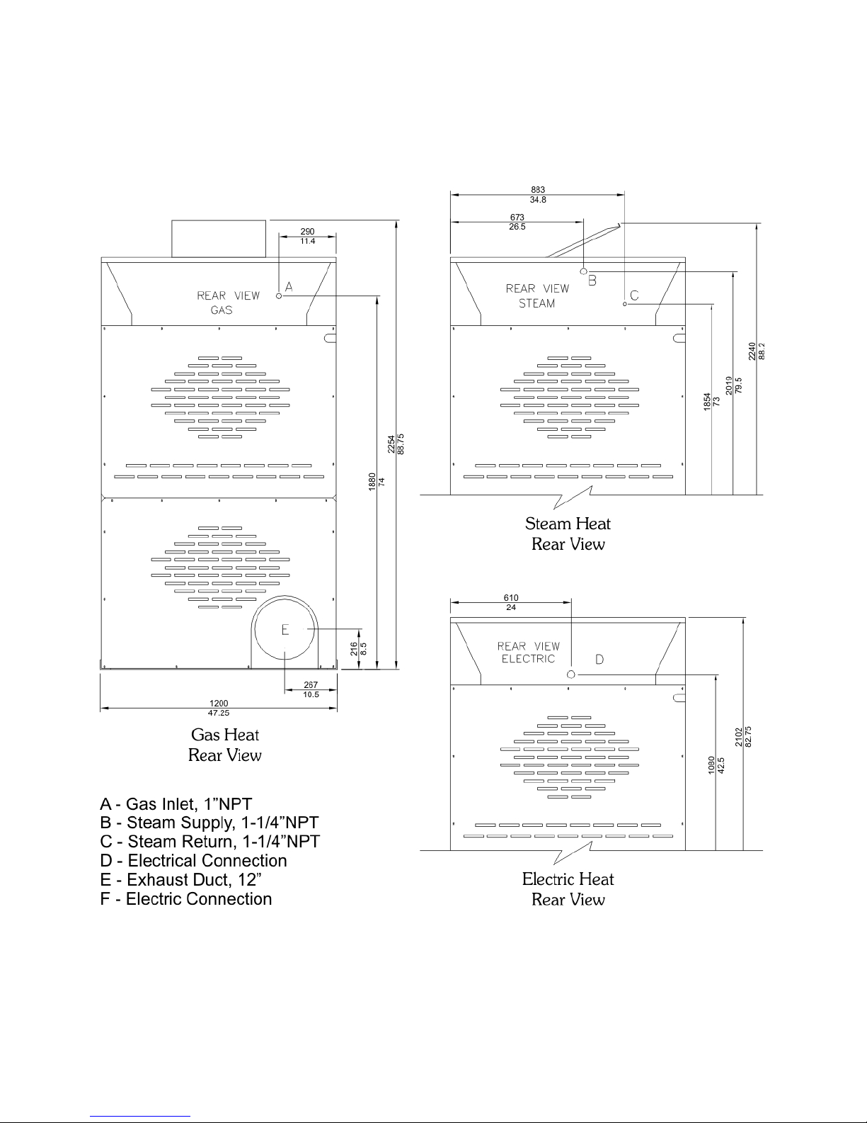
Figure 3.4: DE-120 Utility Connections
12
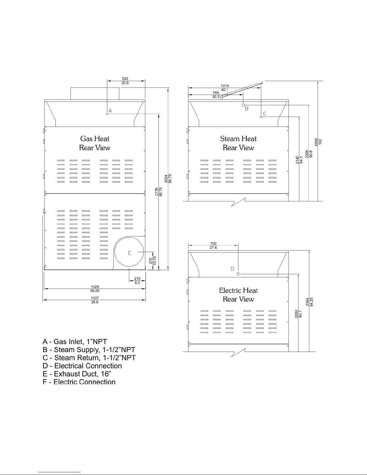
Figure 3.5: DE-170 Utility Connections
13

Figure 3.6: Gas/Steam Heat Electrical Requirements
Figure 3.7: Electric Heat Electrical Requirements
3.2 Electrical Installation
Electrical connections should be made by a qualified electrician in accordance with all applicable
codes or requirements. Use a separate branch circuit to power each machine. Do not share circuits
with lighting or any other equipment.
A shielded liquid tight or approved flexible conduit with proper conductor of correct size installed
in accordance with National Electric Code (USA) or other applicable codes is required. The connec-
tion must be made by a qualified electrician using the wiring diagram provided with the machine.
For personal safety and for proper operation, the machine must be grounded in accordance with
state and local codes and in the USA in accordance with the National Electric Code, article 250-96.
The ground connection must be to a proven earth ground, not to conduit or water pipes.
Do not connect the ground to the neutral (N) leg at the terminal strip (if so equipped).
If a DELTA supply system is used, the high leg should be connected to L3, since control voltage is
derived from L1 and L2.
Insure that the control transformer taps are connected in accordance with the incoming line volt-
age. Verify connections as shown on the schematic with each machine.
Note:
Ensure that all power connections are tight. Loose connections will
cause burned wires and contactors on electrically heated machines.
Check the electrical connections at the incoming power terminal block,
contactors, and heating elements at installation, after the first week of
operation, and quarterly thereafter. Failure of switchgear due to negli-
gence in this area is not covered under any warranty!
14
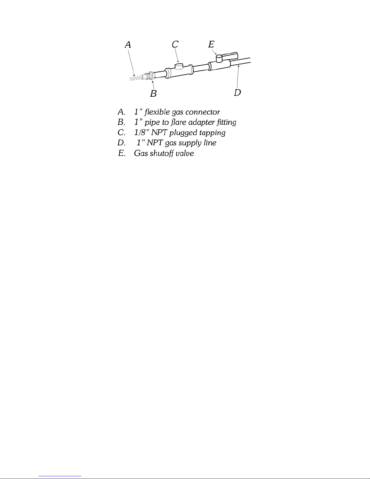
Figure 3.8: Gas Plumbing Detail
3.3 Gas Connection
3.3.1 Gas Supply Line
•1” IPS pipe is recommended.
•1” approved tubing is acceptable for lengths under 25 ft (6.1 m) if local codes and gas supplier
permit.
•Must include 1/8” NPT minimum plugged tapping accessible for test gauge connection,
immediately upstream of the gas connection to the dryer (see figure 3.8 on page 15).
•Must include a shutoff valve:
An individual manual shutoff valve must be installed within 6 feet (1.8m) of the equip-
ment in accordance with the National Fuel Gas Code, ANSI Z223.1. The location should
be easy to reach for opening and closing.
3.3.2 Gas Supply Connection Requirements
There are many methods by which the DE series dryer can be connected to the gas supply. Fol-
lowing are some guidelines for methods of connection.
Option 1:
Flexible stainless steel gas connector:
If local codes permit, use a new flexible stainless steel connector (Design certified by the American
Gas Association or CSA International) to connect between the dryer and the gas supply line. Use
15

an elbow and a 1” flare x 1” NPT adapter fitting between the stainless steel gas connector and the
gas inlet of the machine as needed to prevent kinking.
Option 2:
Other approved piping:
Lengths under 25 feet (6.1m) use 1” approved tubing.
Lengths over 25 feet (6.1m) should use larger piping.
Pipe joint compounds that resist the action of gas must be used. DO NOT USE TEFLON R
/PTFE
TAPE.
IMPORTANT: Be certain the dryer is configured for the type of gas being used. The gas type is
shown on the serial sticker on the electrical panel of the unit.
Inlet Pressure
Use a manometer to verify that the inlet pressure meets the following requirements:
Natural Gas service must be supplied at 4-14 inches of water column pressure.
LP Gas service must be supplied at 11-14 inches of water column pressure.
If the incoming gas pressure exceeds the above, install a locally obtained gas regulator that has
sufficient BTU capacity to supply the machine (Maxitrol 325-5AL for up to 300,000 BTU, 327-7L
for up to 900,000 BTU or equivalent). A chattering gas valve indicates improper line pressure, not
a faulty gas valve.
Manifold Pressure (Secondary)
Be sure to check the manifold pressure. Use a manometer to verify that the manifold pressure
matches the information on the serial sticker and the type of gas being used. A separate gas
regulator (locally obtained) must be installed if the incoming line pressure is greater than 14 inches
water column pressure.
1. Connect the manometer to the pressure connection on the gas valve (disconnect gas service).
2. Restore gas service, and determine the pressure while the burner is ignited. The pressure
must match the indicated manifold pressure on the serial sticker.
Gas Conversion Notice: Do not connect a machine configured for Natural Gas to LP Gas service or
vice-versa without a qualified service technician doing a proper conversion. After the reconfigura-
tion is complete, the manifold pressure must be verified. See Section 8.1 on page 39 for conversion
details.
3.4 Steam Connection
For best results, operate with a steam pressure of 90 psi (6.2 bar). The steam inlet and return are
located on the rear of the machine.
16

Important: Insulate all steam and return lines for the safety of the operator and service technician.
Important: All steam components must be rated for a minimum of 200 psi (14 bar) working pres-
sure. Shut off valves must be installed upstream of the steam inlet, and downstream of the steam
trap so that the equipment can be isolated for maintenance or emergency.
Important: Support all steam lines and components to minimize the load on the steam connections
to the dryer.
Obtain steam service piping from a steam system supplier or a qualified steam fitter.
Use a minimum of 12 inch (300mm) rise above the header to prevent condensate from draining
into the dryer. Do not make a steam connection to the header with a horizontal/downward facing
tee or elbow.
Wherever possible, horizontal runs of steam lines must gravity drain to the steam header. Water
pockets or improperly drained headers will yield poor results due to wet steam.
Install a union and valve in the steam supply and return lines for ease of service.
For best performance, install an inverted bucket trap with strainer and a check valve. Avoid ther-
mostatic traps. For best results, install the trap at least 18 inches (450mm) below the inlet and as
close to the machine as possible. Install the trap according to the instructions with the unit, noting
the steam flow direction. If the steam is gravity returned to the boiler, install a vacuum breaker
and check valve in the return line near the machine. Note that all return plumbing must be below
the return inlet.
To prevent eventual water hammer, route all return lines below steam outlets.
Table 3.1: DE Series Steam Condensate Loading
Steam Pressure Machine
DE-30 DE-50 DE-75 DE-120 DE-170
60 PSIG 904.7 99.5 lbs/hr 143.7 lbs/hr 221.1 lbs/hr 414.5 lbs/hr 607.9 lbs/hr
70 PSIG 898 100.2 lbs/hr 144.8 lbs/hr 222.7 lbs/hr 417.6 lbs/hr 612.5 lbs/hr
80 PSIG 891.9 100.9 lbs/hr 145.8 lbs/hr 224.2 lbs/hr 420.5 lbs/hr 616.7 lbs/hr
90 PSIG 886.2 101.6 lbs/hr 146.7 lbs/hr 225.7 lbs/hr 423.2 lbs/hr 620.6 lbs/hr
100 PSIG 880.8 102.2 lbs/hr 147.6 lbs/hr 227.1 lbs/hr 425.7 lbs/hr 624.4 lbs/hr
125 PSIG 868.3 103.7 lbs/hr 149.7 lbs/hr 230.3 lbs/hr 431.9 lbs/hr 633.4 lbs/hr
3.5 Steam Damper
The DE-120 and DE-170 are manufactured with a pneumatic (piston) damper system which re-
quires an external supply of compressed air. The air connection is made to the steam damper
solenoid valve which is located at the rear inner top area of the dryer just above the electric service
relay box. See Table 3.2 on page 18 for details.
17
This manual suits for next models
5
Table of contents


