B&C BC3500 User manual

1
BC3500
Trailer Winch
BC3500
Owners / Installation Guide
model
BC3500ATV
BC3500CP
BC3500CPR
Read and understand guide before
installation and use of BC3500

2
Introduction BC3500
Thank you for choosing a BC3500.
Please read this owner’s manual to fully understand the product and provide you with
safe and reliable performance.
The BC3500 is a compact, powerful, high performing and versatile winch.
It comprises of a 1.2kW DC permanent magnet motor,140:1 ratio 3 stage heavy duty
gearing, automatic load holding brake and stronger steel fabricated drum.
The stronger fabricated steel drum on all models provides the best & safest option to use
either steel or synthetic rope.
With sealed motor and gearbox the BC3500 has an IP68 rating to provide protection from
water, dirt and dust.
The BC3500 operation has ability to power forward and reverse and with freespool as
standard feature.
Winch control options consist of wired remote, wireless remote and permanent mounted
waterproof switch.
Specifications BC3500
Rated Line Pull 1590 kg (3500 lb) single line pull
Gear Box 3 Stage planetary
Gear Ratio 140 : 1
Motor 12v 1.2 kW 1.6 hp)
Motor 24v 1 kW (1.3hp)
Dimensions As per line drawings in this manual.
Weight Range unboxed 10.5 kg 12 kg 13.3 kg
Mounting 2, bolt, 3 bolt or 4 bolt
Rope maximum length 10M & 15M of 5mm steel or synthetic option
Performance As per performance chart in this manual
Current Draw Maximum 260 Amps
Freespool Rotate lock & unlock

3
Performance BC3500 recovery winch
Fist layer Performance
Line Pull in kg (lb’s) Line Speed M p/m (Ft p/m) Current Draw Amps 12V
O load 7.5 (24.6) 23 Amps
227 kg (500 lb) 5.9 (19.3) 45 Amps
454 kg (1000 lb) 5.3 (17.3) 67 Amps
680 kg (1500 lb) 4.6 (15.3) 90 Amps
907 kg (2000 lb) 4.12 (13.8) 114 Amps
1134 kg (2500 lb) 3.7 (12.3) 138 Amps
1361 kg (3000 lb) 3.3 (10.8) 164 Amps
1588 kg (3500 lb) 2.8 (9.3) 190 Amps
Important !!
It is the installers and operators responsibility that before use the BC3500 is
mounted to a suitable platform or structure.
It is to be correctly and adequately secured capable to stand all loads applied with
suitable margin of safety. Consult a structural engineer if uncertain.
Suitable ropes must be used with suitable minimum breaking strain.
A SK78 minimum 5 mm diameter Dyneema
If a high tensile steel rope is used a minimum diameter of 5 mm is required.
The BC3500 must not be used for lifting, supporting or transportation of people.
The BC3500 must not be used to support, move or hold loads above people.
The BC3500 must always be used in a safe manner, making sure hands, body
parts and all people are clear of the rope and objects being moved while the
BC3500 is in use.
Never use the BC3500 for securing loads while transporting.
Allow slack in the rope between the load an winch during transport.
Use suitable rated load restraints for load securing.

4
Safety and Precautions
It is important all precautions are take for the safe operation of the BC3500..
It is the owner’s and operator’s responsibility to understand the correct safe installation
and operation of the BC3500. This will help to avoid injury, death and or damage to prop-
erty.
This manual will assist the owner with product information and installation.
Additional information is provided for safety guidance, contrary use or installation can re-
sult in injury, death and damage to property.
Safe Operation
Be sure the BC3500 has been installed and wired correctly before use. Inspect mounting
hardware is secure.
Check rope is winding on correctly, incorrect wind on direction will have no brake load
holding. Rope must feed onto the bottom of the drum, looking at the winch from the rope,
motor is on the left.
Inspect rope is not damaged, damaged rope can fail resulting in rope breaking, causing
loss of load, death, injury or damaged property.
Be certain the winch rope is secured to the load at a suitable location with adequate
strength for load applied. Use safety sling if no suitable anchor point is available.
Always make sure winch rope is being applied onto the winch in a straight line horizontal
to the ground and at 90 degrees to the winch.
Use directional pulley if needed, ensure the rope is always at the correct height level and
direction. Wind rope evenly onto the drum.
Make sure all areas between the winch and the load are clear of obstruction and people,
stand clear of the rope when winching., keep hands clear from the winch.
Avoid stop start recovery, plan for one continuous single operation. Do not have repetitive
loads without allowing winch to cool. Do not use the winch at high load for extend period
of time.
If the motor gets to hot allow adequate time for cooling. Do not put your hands on a hot
motor. Allow motor to cool until a comfortable to touch temperature.
Overheating will result in winch failure.
When winch is not in use remove control switch or remote were fitted.
Shut off power supply to the winch where possible.
Never leave the winch unattended while under load. Visual contact must be maintained of
the winch and load during operations.
Important !!

5
Options & operation BC3500
The BC3500 is supplied with many options and accessories.
This makes it versatile to suit your installation and application.
The BC3500 supplied as an ATV version is supplied with a mount
plate suitable for hawse or roller fairlead mounting.
A standard base plate can be requested if no hawse or roller is
not required.
The aluminium hawse is not to be used with steel rope and the
roller fairlead may be required.
If a hawse or roller is used the winch rope can only be in the un-
derwound direction. Rope winding is explained in under rope in-
stallation.in this manual.
The BC3500 supplied with control box mounted and used with
rope in overwound direction can not be used with mounted
hawse or roller fairlead.
This installation may be used on boat & car trailers to maintain
the most direct line for boat retrieval.
Over wound rope will have the winch motor to the right and gear-
box to the left when viewing the winch mount with the rope com-
ing towards you..
The BC3500 supplied with control box mounted and used with
rope in underwound direction .
This installation may also used on boat & car trailers to maintain
the most direct line for boat retrieval.
Under wound rope will have the winch motor to the left and gear-
box to the right when viewing the winch mount with the rope
coming towards you.
In most trailer applications the rope is always feeding onto the
winch in direct line 90 degrees to the drum. In this situation a
guide hawse or roller fairlead offers minimal benefit.
The BC3500 supplied with control box mounted and used with
rope in underwound direction .
This installation may also used on boat & car trailers to maintain
the most direct line for boat retrieval.
Under wound rope will have the winch motor to the left and gear-
box to the right when viewing the winch mount with the rope
coming towards you.
This option is also available with mounted hawse or roller fair-
lead for use with steel rope.
BC3500 accessories. Include wireless controls & roller fairlead.

6
Dimensions BC3500ATV

7
Dimensions BC3500 control box

8
Mounting BC3500
Correct mounting of the BC3500 is the customers responsibility.
Before mounting your BC3500 inspect for and signs of possible damage and all assembly
bolts and screws are secure.
Mounting hardware must be of a minimum M8 high tensile grade 8 bolts.
M10 bolts may be used with non hawse mount plate.
Dimensional diagram shows cut outs in mounting plate for suitable securing positions.
A minimum of two mounting bolts must be used being centre holes front hole and rear.
The bolts must be secured with spring washer behind the nut or lock nut should be used.
Two flat washers should be used on the bolts on both sides of the mounting plate one un-
der the bolt head and one under the lock washer or lock nut. Ensure all nuts are firmly
secured at 30 Nm of torque for M8.
The use of undersized or under strength bolts can result in the mounting failing under
load. This can result in injury, death or damage.
The mounting platform or structure must be of adequate strength to support the full line
pull capability of the winch. Plus incorporate a safety factor which will eliminate possible
distortion of the mounting platform. A steel mounting platform of 6mm thickness may be
required. Seek qualified engineering support if uncertain.
The BC3500 must be located in a position it will not be submerged in water.
The BC3500 can be mounted horizontally or inverted but must be mounted so the rope
feeds on in a direct straight line either from the load or via a pulley block.
When mounted the rope must feed onto the winch drum from the underside of the drum
when looking at the winch with the motor to the left and gearbox on the right.
Incorrect installation of the rope will eliminate the load holding mechanical brake.
9
Incorrect wiring can result in short circuit, fire and damage.
Double check all wiring.
Once inspected connect power cables to the battery
Test winch both forward and reverse directions
A circuit breaker will prevent over loading, overheating or damaging the
BC3500.
Fitting instructions of a circuit breaker are included in the manual and is
connected to the main positive cable from the battery.
Follow wiring instructions provided in the manual to suit your winch model.
Always provide power to the winch direct from + & - battery.
DO NOT use vehicle chassis or body for negative supply.
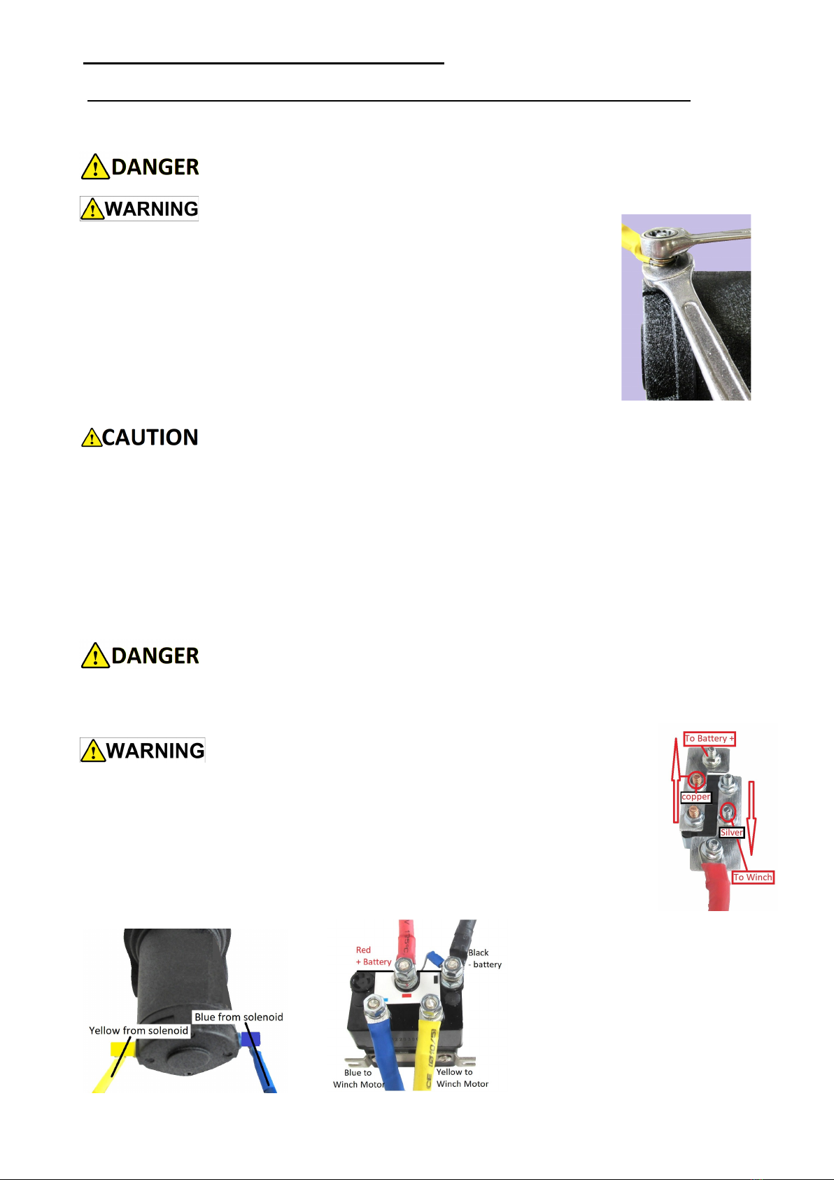
Electrical Installation BC3500 ATV
The motor and solenoid terminal have lower and upper securing nut.
Remove the upper nut and washer. It is important to inspect the lower
nut is firm but do not overtighten.
Apply the power cable lug eye over the bottom nut. Use flat washer on
either side were provided or spring washer below the upper nut.
Use a spanner to support the lower nut when tightening and securing
the upper nut. Tighten nuts to maximum torque 5Nm.
This will help prevent over tightening and turning of motor or solenoid
terminal, rotation of the terminal will result with internal damage to the
motor or solenoid.
When routing the power cables select a suitable path which will not interfere with
the operation of the winch or be in the path of the winch rope.
Use additional protection on the wiring conduit which comes into contact with sharp
objects or any surface which can rub and wear the electrical conduit.
Power cables should be at shortest required length where possible.
A qualified electrician may shorted cable length if required.
Make sure the wiring is clear of any surfaces which have the potential to get hot.
Any additional length or loose and hanging wiring must be secured with cable ties
to strong support out of harms way.
Damaged wiring must not be used.
Damaged wiring can result in short circuit, fire and electric shock.
Avoid electric shock. Disconnect battery when installing
the winch

10
Electrical Installation BC3500 ATV
Battery Not included
Ignition Switch Not included
Handlebar
Switch
Only one switch required for
winch operation, both can be
installed

11
Electrical Installation BC3500 CP & CPR
The BC3500 CP & CPR is wired with an Anderson plug for easy installation..
An additional plug is provided to connect to a vehicle battery or independent battery.
The BC3500 solenoid control box has a 4 pin sock with
locating notch. This is used for all plug in control options..
The socket is suitable to accept the corded hand held
control or the wireless receiver.
Plug in corded remote forward and reverse control
Wireless receiver plugs into the control box
Wireless receiver can become corded remote to plug
into control box

12
The BC3500 is suited to both steel or synthetic rope.
In either installation the rope is fed under the drum from the front of
the winch and then into the drum from behind the winch. This is
correct with the motor on your left and gearbox on your right when
facing the winch. Incorrect rope attachment will not allow the brake
to function correctly and support loads..
Wear leather gloves when handling steel ropes
STEEL ROPE.:
For best performance determine the working length of rope required plus additional 5
wraps of first layer on the drum. The first 5 wraps are important to help secure the rope
on the drum. Do not exceed maximum rope length recommendation.!
When installing the steel rope pass under the drum and then into the hole in the drum
from behind the winch.
The grub screw used to retain the steel rope may need to be unwound to allow the rope
to pass. Push the rope through and loop it through the second hole, push until flush with
the drum hole on the outer side.
Tighten the grub screw until firm and slight crush on the steel rope, Apply the rope onto
the drum under tension of minimum 5kN. Guide the rope so it layers onto the drum even-
ly, overlapping the rope will damage the rope.
SYNTHETIC ROPE :
When selecting a synthetic rope for be certain to select a quality rope suitably rated for
such applications.
Do not use excessive rope, maintain a suitable working length plus first layer on the
drum.
Unused rope compresses and flattens onto the drum, this creates extreme pressure on
the barrel and against the cheek plates of the drum. This may damage the drum and the
rope.
If applying synthetic ropes to a winch once having steel rope carefully inspect the drum
surface for any abrasive surface.
The first layer of rope applied to the drum secures the rope
onto the drum.
The first layer should be applied under load of minimum 5kN
and must always remain on the drum when BC3500 is used.
The remaining rope is to be layered onto the drum evenly.
Synthetic ropes should only be used where abrasion or
sharp edges can be avoided.
Get information regarding any replacement rope you use for
strength and longevity and consideration of being used in an
environments with high ultraviolet exposure.
All rope should be inspected before use for wear and damage.
The BC3500 is powerful enough to sever fingers. Keep fingers clear of the rope at the
drum or where it may be in contact with any surface. Avoid handling the rope.
Rope Installation BC3500

13
BC3500 parts exploded view.

14
Maintenance BC3500
The BC3500 gearbox is lubricated with an extreme pressure lithium grease. No additional
lubrication is expected for the life of the winch. If re-lubrication is performed use only
compatible grease.
1/ Regular inspection for tightness of all bolts should be performed to maintain safe se-
cure mounting. All assembly bolts should also be inspected for tightness.
2/ Electrical connections must be regularly inspected to ensure they are tight and secure.
4/ Servicing or repairs must only be undertaken by approved service centre.
5/ Remove any dirt or moisture from ropes and winch
Any worn or damaged components must be replaced.
Do not use the BC3500 if any parts are damaged. Use only genuine replacement parts.
Inspection of ropes to be performed before each operation if any damaged to the rope it
must be replaced before use.
Replace rope if damaged or worn, kinked or frayed..
Trouble Shooting BC3500
Symptom Possible cause Remedy
Winch will not operate Flat Battery
Brocken connection
Damaged switch
Damaged solenoid
Damaged motor
Circuit breaker tripped
Replace battery
Check all connections
Replace switch
Check / Replace solenoid
Replace motor
Reset circuit breaker
Winch Operates slow
Or low line pull
Low battery supply
Poor earth
Low gauge power cables
Worn or damaged motor
Charge or replace battery
Connect earth direct to battery
Power cable undersize
Replace motor
Winch will not shut off Damaged solenoid
Damaged control switch
Replace solenoid
Replace switch
Winch operates in only
one direction
Solenoid energising wire
Faulty solenoid
Faulty control switch
Check solenoid connections
Replace solenoid
Replace switch
Motor extremely hot Excessive on time
Excessive load
Poor power supply
Allow to cool
Check load weight
Refer slow line pull symptom
Winch will not hold load Load too heavy
Brake is worn or damaged
Cable wound on incorrectly
Check weight of load
Replace brake
Check rope installation guide

15
Wireless Control Duo
Owner’s operating manual
Read and understand the owners manual before use.
It is important to use the Duo safely and responsibly at all times.
Unsafe operation can cause property damage, injury or death.

16
Introduction Wireless Duo control
The Wireless Duo enables the operator to control a winch both the forward and reverse
direction from a distance of 20 metres wirelessly or 4 metres corded.
It is the operators responsibility to use the Duo safely and responsibly,
Read and understand safety precautions outlined in this manual.
1/ Never use the Duo if the winch or device being operated is not clearly visible.
2/ Never operate the winch or devise until all people and property are clear of the area.
3/ Do not use wireless controls in an area where radio interference may effect either the
intended or unintended operation of the Wireless Duo.
The Wireless Duo control includes.
- Plug in screw lock wireless receiver
- Forward and Reverse (In & Out) transmitter
- Adaptable cord to convert from wireless to wired plug in control
- Battery included and installed in transmitter.

17
Wireless Control Operation
The Wireless transmitter comes paired to the
The transmitter has an automatic
shut down to preserve battery life.
It will shut down after 2 minutes if
inactive.
Repeat startup to continue use.
The Wireless receiver comes paired to the transmitter ready for use.
Picture above shows installation of receiver.
The control box socket and receiver adaptor have corresponding location points and
must be paired when mounting the receiver to the socket.
Once inserted the rotating lock sleave can be used to secure the receiver in position.
The receiver is powered by the internal wiring of the control box.
There is no requirements for batteries in the receiver and the unit is sealed.
The Wireless transmitter comes paired to the
receiver ready for use.
Picture shows functions
To Start the transmitter press the On Off
Mode button and hold for 3 seconds.
The indicator light will flash when on and the
transmitter is now ready for use.
The operate buttons when pressed will signal
the receiver with your selected function.
Release pressure from the button and the
function will cease.
To switch off again press the On Off Mode
button and hold for 3 seconds.

18
Wireless Control Corded Opera-
The Wireless transmitter can become a 4 me-
tre corded control when required or if preferred.
There is a Wired Lead In adaptor at the top of
the transmitter. Remove the cap to expose a
locating point which matches that of the cord.
Once connected it has a threaded locking
sleave for retention. The opposite end will plug
into the control box socket, also use the locking
sleave to secured into position .
Once connected the Indicator Light Wired will
confirm the wired control is now in use.
The Operate Out In buttons can now be used.
Pairing receiver to transmitter
If The transmitter is replaced or requires re pairing to the receiver follow these step.
1/ Remove receiver from control box socket but leave power on at the control box.
2/ Hold down On Off Mode Button on transmitter until turned on.
3/ Press In & Out button simultaneously and hold until both Indicator lights remain on.
4/ When lights begin to slowly flash keep your buttons pressed while reconnecting the
receiver to control socket.
5/ Continue holding In Out button down until the indicator light turn off. Release the but-
tons and the receiver and transmitter are now paired.

19
Duo Wireless Control Maintenance
Battery Replacement
The Duo Wireless transmitter is powered by an A23 battery.
Replacing or accessing the battery by removing the rear cover.
Five (5) Philips head screws are located and accessible on the back of
the transmitter.
Remove the screws and cover to gain access to the A23 battery.
Refit the rear cover ensuring the seal is correctly in place.
Trouble shoot Problem
The Duo will not function wirelessly but will corded.?
1/ Check the receiver is correctly mounted into the socket.
2/ Check signal light is activating. Check Battery Power.
3/ Re pair receiver to transmitter.
The duo will not function both wireless and corded.?
1/ Check power supply to the winch.
2/ Make sure control box switch or isolator switch for the winch is on.
This manual suits for next models
3
Table of contents
Popular Winch manuals by other brands


Champion Power Equipment
Champion Power Equipment C20049F Owner's Manual and Operating Instructions

Ingersoll-Rand
Ingersoll-Rand BU7A Product Maintenance Information

1st-Relief
1st-Relief VERSACHOCK manual

Ingersoll-Rand
Ingersoll-Rand Force 5i Series Product Maintenance Information

Dover
Dover TWG Tulsa RUFNEK 80 DESIGN 001 Series Service manual

Huchez
Huchez SVERO MOTORBOX 300 CD 5 instruction manual