Thern 465 User manual

Read this Owner’s Manual
thoroughly before operating
the equipment. Keep it with
the equipment at all times.
Replacements are available
from Thern, Inc., PO Box 347,
Winona, MN 55987,
507-454-2996.
www.thern.com
Owner’s Manual
For Model 465
Worm Gear Hand Winch
IMPORTANT: Please record
product information on
page 2. This information is
required when calling the
factory for service.
A5368F-0218

Owner's Manual for Model 465 Worm Gear Hand Winchpage 2
A5368F-0218
Two-Year Limited Warranty
Thern, Inc. warrants its products against defects in material or workmanship for two years from the date of purchase
by the original using buyer, or if this date cannot be established, the date the product was sold by Thern, Inc. to the
dealer. To make a claim under this warranty, contact the factory for an RGA number. The product must be returned,
prepaid, directly to Thern, Inc., 5712 Industrial Park Road, Winona, Minnesota 55987. The following information
must accompany the product: the RGA number, the date of purchase, the description of the claimed defect, and a com-
plete explanation of the circumstances involved. If the product is found to be defective, it will be repaired or replaced
free of charge, and Thern, Inc. will reimburse the shipping cost within the contiguous USA.
This warranty does not cover any damage due to accident, misuse, abuse, or negligence. Any alteration, repair or
modication of the product outside the Thern, Inc. factory shall void this warranty. This warranty does not cover any
costs for removal of our product, downtime, or any other incidental or consequential costs or damages resulting from
the claimed defects. This warranty does not cover brake discs, wire rope or other wear components, as their life is
subject to use conditions which vary between applications.
FACTORY AUTHORIZED REPAIR OR REPLACEMENT AS PROVIDED UNDER THIS WARRANTY IS THE
EXCLUSIVE REMEDY TO THE CONSUMER. THERN, INC. SHALL NOT BE LIABLE FOR ANY INCIDEN-
TAL OR CONSEQUENTIAL DAMAGES FOR BREACH OF ANY EXPRESS OR IMPLIED WARRANTY ON
THIS PRODUCT. EXCEPT TO THE EXTENT PROHIBITED BY APPLICABLE LAW, ANY IMPLIED WAR-
RANTY OF MERCHANTABILITY OR FITNESS FOR A PARTICULAR PURPOSE ON THIS PRODUCT IS
LIMITED IN DURATION TO THE DURATION OF THIS WARRANTY.
Some states do not allow the exclusion or limitation of incidental or consequential damages, or allow limitations on
how long an implied warranty lasts, so the above limitation or exclusion may not apply to you. This warranty gives
you specic legal rights, and you may also have other rights which vary from state to state.
Note: Thern, Inc. reserves the right to change the design or discontinue the production of any product without
prior notice.
About This Manual
The Occupational Safety and Health Act of 1970 states that it is the employer’s
responsibility to provide a workplace free of hazard. To this end, all equipment
should be installed, operated, and maintained in compliance with applicable trade,
industrial, federal, state, and local regulations. It is the equipment owner's respon-
sibility to obtain copies of these regulations and to determine the suitability of the
equipment to its intended use.
This Owner’s Manual, and warning labels attached to the equipment, are to serve
as guidelines for hazard-free installation, operation, and maintenance. They should
not be understood to prepare you for every possible situation.
The information contained in this manual is applicable only to the Thern Model
465 Hand Winch. Do not use this manual as a source of information for any other
equipment.
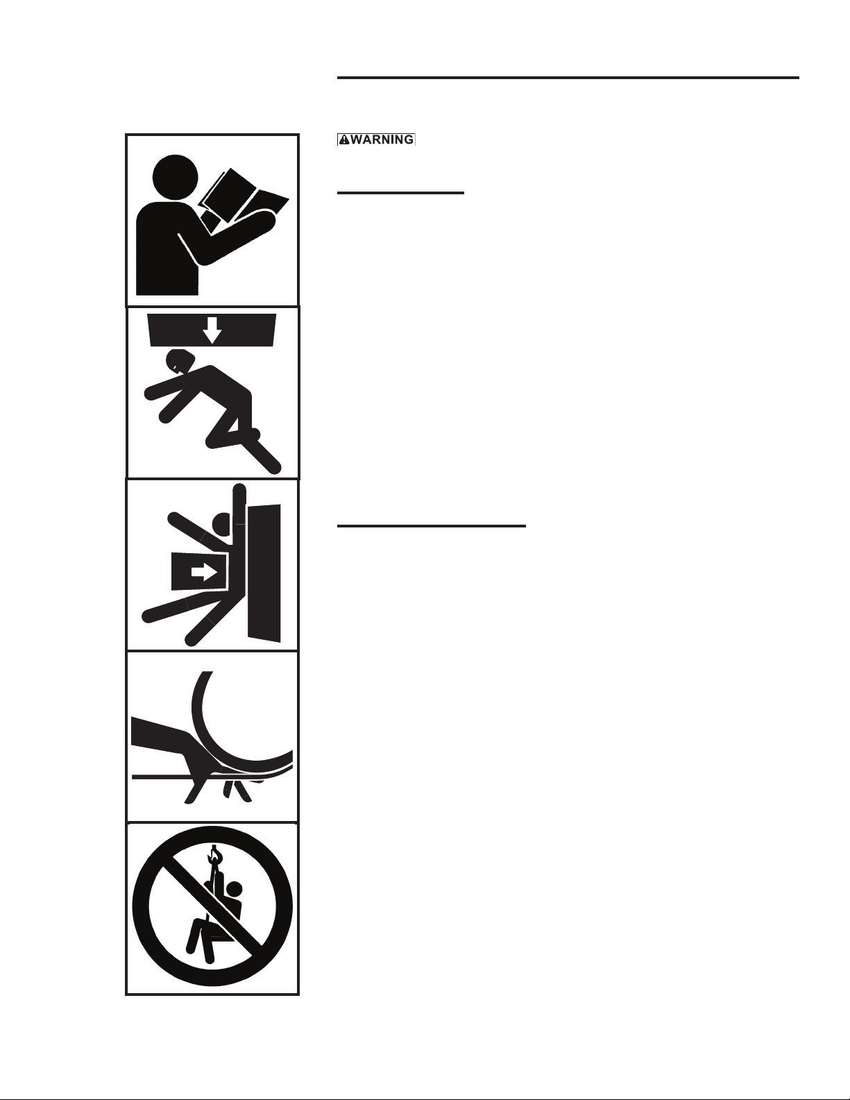
The following symbols are used for emphasis throughout this manual:
Failure to follow ‘WARNING!’ instructions may result in equipment damage,
property damage, and/or serious personal injury.
Failure to follow ‘CAUTION!’ instructions may result in equipment damage,
property damage, and/or minor personal injury.
Important!
Failure to follow ‘important!’ instructions may result in poor performance of
the equipment.
Please record the following:
Date Purchased:
Model No.:
Code No.:
This information is required when
calling the factory for service.
Owner's Manual for Model 465 Worm Gear Hand Winch page 3
A5368F-0218
Suggestions for Safe Operation
DO the following:
Read and comply with the guidelines set forth in this Owner’s Manual. Keep
this manual, and all labels attached to the winch, readable and with the equip-
ment at all times. Contact Thern, Inc. for replacements.
Check lubrication before use.
Install the wire rope securely to the winch drum.
Keep at least 4 wraps of wire rope wound on the drum at all times, to serve as
anchor wraps. With less than 4 wraps on the drum the wire rope could come
loose, causing the load to escape.
Keep hands away from the drum, gears, wire rope, and other moving parts of
the equipment.
Keep all unnecessary personnel away from the winch while in operation.
Keep out of the path of the load, and out of the path of a broken wire rope
that might snap back and cause injury.
DO NOT do the following:
Do not move people, or things over people. Do not walk or work under a load
or in the line of force of any load.
Do not exceed the load rating of the winch or any other component in the
system. To do so could result in failure of the equipment.
Do not operate with other than manual power.
Do not use more than one winch to move a load unless each winch was de-
signed for use in a multiple winch system.
Do not use damaged or malfunctioning equipment. To do so could result in
failure of the equipment.
Do not modify the equipment in any way. To do so could cause equipment
failure.
Do not operate the winch using any form of power other than the hand power
of a single operator.
Do not wrap the wire rope around the load. This damages the wire rope and
could cause the load to escape. Use approved rigging connectors to secure the
wire rope to the load.
Do not divert your attention from the operation. Stay alert to the possibility of
accidents, and try to prevent them from happening.
Do not jerk or swing the load. Avoid shock loads by starting and stopping the
load smoothly. Shock loads overload the equipment and may cause damage.
been taken to secure the load and keep people away from the winch and out
from under the load.

Owner's Manual for Model 465 Worm Gear Hand Winchpage 4
A5368F-0218
1.1 Installing the Winch
-
tric Code, unless installation in such an area has been thoroughly approved.
-
plosives, or other elements that may damage the winch or injure the operator.
Adequately protect the winch and the operator from such elements.
Position the winch so the operator can stand clear of the load, and out of the
path of a broken wire rope that could snap back and cause injury.
Attach the winch to a rigid and level foundation that will support the winch
and its load under all load conditions, including shock loading.
1.1.1 CONSULT APPLICABLE CODES AND REGULATIONS for specic
rules on installing the equipment.
1.1.2 LOCATE THE WINCH in an area clear of trafc and obstacles. Make sure
the winch is accessible for maintenance and operation.
1.1.3 MAINTAIN A FLEET ANGLE between 1/2 and 1-1/2 degrees. The proper
eet angle minimizes wire rope damage by helping the wire rope wind uni-
formly onto the drum. See Figure 3.
1.1.4 POSITION THE WINCH to allow access for proper lubrication.
1.1.5 FASTEN THE WINCH securely to the foundation.
a FOR STANDARD PRODUCTS referred to in this manual, use 3/8-inch
coarse thread fasteners, grade 5 or better. Torque for grade 5 fasteners with-
out lubrication is 30 ft. lbs. Make sure mounting holes are secured to a solid
foundation able to support the winch and the load under all conditions with
design factors based on accepted engineering practices.
b NON-STANDARD PRODUCTS that vary from the original design may
have different fastening requirements. Contact a structural engineer or
Thern, Inc for this information.
TO COMPLY WITH LOCAL CODES, CONTACT A QUALIFIED PROFES-
SIONAL TO OBTAIN PROPER STRUCTURE OR FOUNDATION SPECIFICA-
TIONS FOR THE MOUNTING OF THERN PRODUCTS.
Important!
• Inspect the winch immediately
following installation according
to the Instructions for Periodic
Inspection. This will give you
a record of the condition of the
winch with which to compare
future inspections.
• A qualied professional should
inspect or design the founda-
tion to insure that it will provide
adequate support.
• Locate the winch so it will be vis-
ible during the entire operation.
• Do not weld the winch frame to
the foundation or support struc-
ture. Welding the frame may void
warranty, contact Thern, Inc. Use
fasteners as instructed.

Owner's Manual for Model 465 Worm Gear Hand Winch page 5
A5368F-0218
Figure 1 – Handle
Adjustment
Figure 3 – Maintaining the Fleet Angle
When wire rope travels over a sheave or through a roller guide – maintain eet
angle by locating the sheave or guide an appropriate distance from the drum,
shown as distance “A”. smooth
drum
1/2 to 1-1/2 degrees
distance “A”
center
line
xed sheave or
roller guide
When wire rope travels directly to the load – maintain eet angle by controlling side-
to-side movement of the load with tracks or guide rails. Allowing the load to move
too far to one side causes stress on the drum ange which may cause damage.
1/2 to 1-1/2 degrees center
line
smooth drum
tracks or guide rails
load
Important!
• Use a sheave or roller guide to
direct the wire rope to the drum
whenever possible.
• Install sheaves, tracks and other
equipment so they will remain
xed under all load conditions.
Follow the recommendations of
the equipment manufacturer.
• Use sheaves of proper diameter to
minimize wear on the wire rope.
Follow the recommendations of
the sheave manufacturer.
1.2 Installing the Handle
1.2.1 INSERT THE HANDLE in the handle socket and tighten the set screw to
hold it in place. See Figure 1.
a SHORTEN HANDLE LENGTH for light loads or fast operation.
b INCREASE HANDLE LENGTH for heavy loads or slow operation.
1.2.2 INSERT THE COTTER PIN in the hole in the end of the handle, and bend
the arms back to secure it in place. See Figure 2.
smaller turning
radius:
• lighter loads
• faster
larger turning
radius:
• heavier loads
• slower
loosen fastener
to adjust handle
length
bend arms back
Figure 2 – Cotter Pins

Owner's Manual for Model 465 Worm Gear Hand Winchpage 6
A5368F-0218
1.3 Installing the Wire Rope
Install the wire rope securely to the winch drum. A poorly secured wire rope
could come loose from its anchor and could allow the load to escape.
Install the wire rope so it is wound correctly as shown, or the winch will not
work properly, and could allow the load to escape, see Figure 4.
1.3.1 PURCHASE THE PROPER WIRE ROPE for your application. Keep the
following in mind when selecting a wire rope. Contact a reputable wire rope
supplier for help.
aBREAKING STRENGTH of new wire rope should be at least 3 times great-
er than the largest load placed on the equipment.
bWIRE ROPE LAY must agree with the winding direction of the drum to
help insure proper winding.
cWE RECOMMEND 7 x 19 galvanized aircraft cable for diameters 1/8 or
3/16 inch.
1.3.2 INSERT THE WIRE ROPE between the anchor bolt and the drum ange,
wrap the wire rope around the drum one time, and tighten the anchor bolt
until it attens the wire rope against the drum. See Figure 4.
1.3.3 WIND FOUR FULL WRAPS of wire rope onto the drum by operating the
winch while holding the wire rope taught. These wraps serve as anchor
wraps and must remain on the drum at all times.
Important!
• Use wire rope and other rigging
equipment rated for the size of the
largest load you will be moving.
• Do not drag the wire rope
through dirt or debris that could
cause damage, or poor operation.
• Always wear protective clothing
when handling wire rope.
Figure 4 – Installing Wire Rope
correct incorrect
tighten
anchor
bolt
typical installation shown
right lay - underwound

Owner's Manual for Model 465 Worm Gear Hand Winch page 7
A5368F-0218
2.1 General Theory of Operation
2.1.1 THE PULL REQUIRED to move the load must not exceed the load rating of
the winch. Consider the total force required to move the load, not the weight
of the load.
2.1.2 THIS EQUIPMENT CAN DEVELOP FORCES that will exceed the load
rating. It is the responsibility of the equipment user to limit the size of the
load. Inspect the equipment regularly for damage according to the instruc-
tions contained in this manual.
2.1.3 THE TURNING RESISTANCE of worm gearing decreases with age. Al-
though a new winch may appear to hold the hold in place, this characteristic
will diminish with use. Do not depend on worm gearing to hold the load
in place.
2.1.4 PERFORMANCE RATINGS of the equipment are affected by the amount
of wire rope wound on the drum, the way in which it is wound, and the way
the winch is used.
aDRUM CAPACITY depends on how tightly and evenly the wire rope is
wound on the drum. Actual drum capacities are usually 25-30% less than
values shown in performance tables, due to loose winding and overlapping.
b FORCE REQUIRED TO MOVE the load increases with each additional
layer of wire rope wound onto the drum.
c LOAD RATING represents the maximum pull that can be placed on new
equipment. Load ratings are assigned values for specic amounts of load
travel or wire rope accumulation. The load rating decreases as layers of wire
rope accumulate on the drum.
2.1.5 DUTY RATINGS refer to the type of use the equipment is subject to. Con-
sider the following when determining duty rating.
aENVIRONMENT: harsh environments include hot, cold, dirty, wet, corro-
sive, or explosive surroundings. Protect the equipment from harsh envi-
ronments when possible.
bMAINTENANCE: poor maintenance, meaning poor cleaning, lubrication,
or inspection, leads to poor operation and possible damage of the equipment.
-
tained in this manual.
cLOADING: severe loading includes shock loading and moving loads that
exceed the load rating of the equipment. Avoid shock loads, and do not
exceed the load rating of the equipment.
dFREQUENCY OF OPERATION: frequent or lengthy operations increase
wear and shorten the life span of gears, bearings, and other components.
Increase maintenance of the equipment if used in frequent operations.
CONTACT THE FACTORY FOR MORE INFORMATION.
Important!
• Limit nonuniform winding by
keeping tension on the wire rope
and by maintaining the proper
eet angle.
• It is your responsibility to detect
and account for different fac-
tors affecting the condition and
performance of the equipment.
Owner's Manual for Model 465 Worm Gear Hand Winchpage 8
A5368F-0218
2.2 Breaking-In the Winch
2.2.1 BREAK-IN OCCURS during the rst 10 hours of normal operation. During
break-in, mating surfaces become polished, and clearances increase. This is
desired for efcient operation of bearings and gears.
2.2.2 INSPECT THE WINCH following break-in according to the Instructions for
Periodic Inspection. See Section 3.3 Inspecting the Equipment.
2.3 Preparing for Operation
2.3.1 CONSIDER THE OPERATION. Do not begin until you are sure you can
perform the entire operation without hazard.
2.3.2 INSPECT ALL COMPONENTS of the system.
a INSPECT THE WINCH and other equipment according to the Instructions
for Frequent Inspection.
b OPERATORS MUST be in good health, alert, thoroughly trained in operat-
ing the equipment, and properly clothed (hard hat, safety shoes and safety
glasses, no loose clothing).
c LOAD MUST be clear of other objects and free to move. Make sure the load
will not tip, spin, roll away, or in any way move uncontrollably.
2.3.3 KNOW YOUR LOAD and make sure you do not exceed the load rating of
the winch or any other equipment in the system.
2.4 Attaching the Load
Do not wrap the wire rope around the load. This damages the wire rope and
could cause the load to escape. Use a sling or other approved rigging device.
2.4.1 CLEAR OBJECTS from the path of the load so you can move it freely and
observe it at all times during the operation.
2.4.2 ATTACH THE LOAD using a nylon sling, or other approved rigging de-
vice. Follow the recommendations of the sling manufacturer.
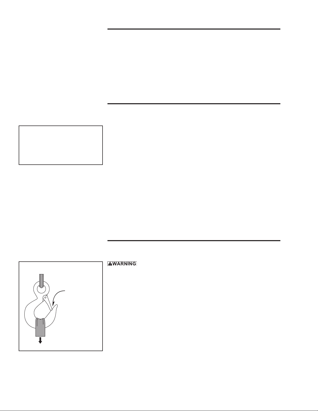
a SEAT THE SLING in the saddle of the hook with the hook latch completely
closed. See Figure 5.
b CENTER THE LOAD on the hook so it will remain balanced and not tip or
rotate to one side.
Figure 5 – Attaching Load
latch closed
tight against
hook
sling seated in
saddle of hook
Important!
• When determining whether the
load will exceed the load rating,
consider the total force required
to move the load.

Owner's Manual for Model 465 Worm Gear Hand Winch page 9
A5368F-0218
2.5 Moving the Load
2.5.1 MOVE THE LOAD slowly and smoothly, only a small distance at rst.
Make sure the load is balanced and securely attached before continuing.
2.5.2 TURN THE HANDLE CLOCKWISE to wind wire rope onto the drum. If
wire rope unwinds from the drum when the handle is rotated clockwise, the
wire rope is installed incorrectly. Install the wire rope correctly before
continuing. See Figure 4.
2.5.3 GRIP THE HANDLE TIGHTLY at all times during operation. If you release
the handle the load may backdrive causing the handle to spin. Do not try to
stop a spinning handle, step clear until the spinning stops.
2.5.4 OBSERVE THE WIRE ROPE as it winds onto the drum. If it becomes
loose, uneven, or overlapped, stop the operation and rewind the wire rope
before continuing. Continued operation with overlapped or uneven wire
rope can damage the wire rope and shorten its life.
Important!
• Obey a stop signal from anyone.
• Maintain tension on the wire
rope to keep it tightly and evenly
wound on the drum.
• If the winch and load are not vis-
ible during the entire operation,
get help from another person.
• Appoint a supervisor if more
than one person is involved in
the operation. This will reduce
confusion and increase safety.
• When lifting a load, use a tag line
to keep the load from swinging or
twisting, while keeping yourself
away from the load.
• Remove the winch handle when
the winch is not in use, to help
avoid unauthorized use.
Owner's Manual for Model 465 Worm Gear Hand Winchpage 10
A5368F-0218
Important!
• Make sure lubricant has a tem-
perature rating appropriate for
the ambient temperatures of the
operation.
3.1 Cleaning the Winch
Clean the winch to remove dirt and help prevent rust and corrosion.
3.1.1 CLEAN THE WINCH every six months or whenever it is dirty.
a WIPE ALL EQUIPMENT to remove dirt and grease.
b LEAVE A LIGHT FILM of oil on all surfaces to protect them against rust
and corrosion.
c WIPE OFF excessive amounts of oil to avoid the accumulation of dirt.
3.1.2 REMOVE ALL UNNECESSARY OBJECTS from the area surrounding the winch.
3.2 Lubricating the Winch
Lubricate the winch properly to help protect it from wear and rust. Read the
following instructions carefully.
3.2.1 CONSULT MANUFACTURER’S RECOMMENDATIONS for specic
information on lubricating the wire rope and other equipment.
3.2.2 LUBRICATE THE WINCH SHAFTS at least every 6 months.
a APPLY 2 TO 3 DROPS of SAE 30 non-detergent oil to shafts and at all fric-
tion points.
b ROTATE THE DRUM several times to allow the oil to penetrate, and wipe
off excess oil to avoid accumulation of dirt.
Important!
Increase the frequency of mainte-
nance procedures if the winch is:
• Operated for long periods.
• Used to pull heavy loads.
• Operated in wet, dirty, hot, or
cold surroundings.
Table 1 – Inspection Checklist
damages problems
general nishweathered,aking,otherwisedamaged winchjerksorhesitatesduringoperation
partscracked,bent,rusted,worn,otherwisedamaged unusualnoises,othersignsofmalfunction
fasteners strippedthreads,bent,worn,otherwisedamaged loose,nottightenedtopropertorque
worm gears excessivelyworn,cracked,corroded,otherwiseddamaged looseorimproperlylubricated
wire rope bent,crushed,otherwisedamaged wireropelooselyorunevenlywound
brokenwires,seeFigure6
replaceifmorethan6wiresinonelay, numberperstrand=
or3wiresinonestrandinonelay,arebroken numberperlay=
diameterreduced,seeFigure8
replaceifdiameterisexcessivelyworn diameter=
end connections corroded,rusted,worn,otherwisedamaged notsecurelyattached
load hook twisted,bent,worn,otherwisedamaged,seeFigure7 hooklatchfailstoclosewhenreleased
replaceiftwistis10degreesormore twist=
replaceifthroatwidthis15%largerthannominal throatwidth=
replaceifthicknessis10%lessthannominal thickness=
labels and plates dirty,illegible,otherwisedamaged looselyattachedormissing
comments:
authorized signature: date
checked boxes indicate damage or problem in need of repair

Owner's Manual for Model 465 Worm Gear Hand Winch page 11
A5368F-0218
3.2.3 LUBRICATE WINCH GEARS before every operation and at least every 10
hours during operation.
a APPLY A LIGHT FILM of open gear lubricant to the gear teeth on all gears.
b USE SPRAYON S00201 or equivalent open gear lube. For dirty conditions
use a dry lubricant such as dry graphite or Moly.
3.2.4 LUBRICATE THE WIRE ROPE by following the wire rope manufacturer’s
recommendations.
3.3 Inspecting the Equipment
sign on the winch. Do not use the winch until the sign is removed by a qual-
Inspect the winch to detect signs of damage or poor operation before they
become hazardous. See Table 1 - Inspection Checklist.
3.3.1 CONSULT APPLICABLE CODES AND REGULATIONS for specic
rules on inspecting the winch and other equipment.
3.3.2 CONSULT MANUFACTURER’S RECOMMENDATIONS for information
on inspecting the wire rope and other equipment.
3.3.3 Instructions for Frequent Inspection
a VISUALLY INSPECT the entire winch and all other equipment involved in
the operation.
• Check all equipment for cracks, dents, bending, rust, wear, corrosion and
other damage.
• Make sure the wire rope is installed correctly and anchored securely to
the drum.
• Make sure the winch is properly lubricated.
• Make sure the fastener holding the handle in place is tight. See Figure 1.
• Make sure mounting fasteners are tightened securely.
• Make sure the foundation is in good condition, and capable of supporting
the winch and its load under all load conditions.
b TEST WINCH PERFORMANCE by operating the winch with a load not
exceeding the load rating.
• Listen for unusual noises, and look for signs of damage as you operate the
winch.
• Make sure the wire rope winds evenly and tightly onto the drum. If it is
loose or uneven, rewind it before continuing.
• Make sure the handle rotates freely in both directions.
• Make sure the load moves smoothly, without hesitation or strain.
Completely correct all problems before continuing. Use the Troubleshooting
Chart to help determine the cause of certain problems. See Table 2.
Important!
• Start an inspection program as soon
as you put the winch into use.
• Appoint a qualied person to be
responsible for regularly in-
specting the equipment.
• Keep written records of in-
spection. This allows comparison
with comments from previous in-
spections so you can see changes
in condition or performance.
Perform frequent inspections:
• Before each operation.
• Every 3 hours during operation.
• Whenever you notice signs of
damage or poor operation.
Frequent Wire Rope Inspection:
• Use ASME B30.7 as a guideline
for rope inspection, replacement
and maintenance.
• Check the wire rope, end connec-
tions and end ttings for corrosion,
kinking, bending, crushing, bird-
caging or other signs of damage.
• Check the number, distribution
and type of visible broken wires.
See paragraph 3.3.4 b and Figure 6.
• Check the wire rope for reduc-
tion of rope diameter from loss of
core support, or wear of outside
wires. See Figure 8.
• Take extra care when inspecting
sections of rapid deterioration
such as sections in contact with
saddles, sheaves, repetitive pickup
points, crossover points and end
connections.
Owner's Manual for Model 465 Worm Gear Hand Winchpage 12
A5368F-0218
3.3.4 Instructions for Periodic Inspection, see table 1.
a VISUALLY INSPECT the winch and all other equipment.
• Disassembly may be required in order to properly inspect individual com-
ponents. Contact factory for assembly/disassembly instructions. Disas-
sembly of the winch before contacting Thern, Inc. voids all warranties.
• Check the nish for wear, aking, or other damage.
• Check all equipment, including wire rope, for cracks, dents, bending, rust,
wear, corrosion and other damage. If the equipment was overloaded, or
if you notice cracks and other signs of overloading and damage promptly
remove equipment from use and have it repaired or replaced. DO NOT
.
• Check all fasteners for stripped threads, wear, bending, and other damage.
• Make sure the winch is properly lubricated.
• Make sure all labels and plates are readable, rmly attached, free of dam-
age and clean. Replacements are available from the factory.
b INSPECT THE WIRE ROPE according to the wire rope manufacturer's rec-
ommendations or follow accepted industry standards for wire rope inspection.
• Always wear protective clothing when handling wire rope.
• Check the entire length of wire rope for bent wires, crushed areas, broken
or cut wires, corrosion, and other damage. Carefully inspect areas that
pass over sheaves or through roller guides.
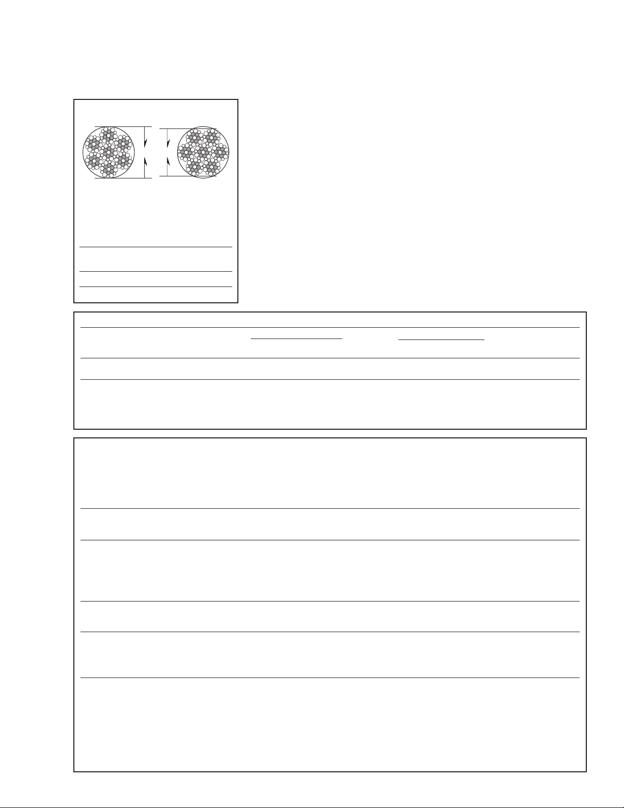
• Note the location and concentration of broken wires. Replace wire rope if
more than 6 wires are broken in one lay, or more than 3 wires are broken
in one strand in one lay. See Figure 6.
• Make sure the load hook or other device is securely attached to the wire
rope, and the wire rope where it is attached is not frayed, corroded, bro-
ken, or otherwise damaged.
• Measure the throat opening, thickness, and twist of the hook. Replace the
hook if it shows signs of damage. See Figure 7.
• Make sure hook latch opens without binding and closes when released.
c MOVE THE DRUM with your hands. Check for excessive movement in-
dicating worn or loose gears, bearings, or shafts. Excessive movement is
caused by overloading or overheating and is a sign that your application may
require a larger winch.
d PLACE enough weight to keep the wire rope straight and tightly drawn.
• Measure the diameter of the wire rope, especially in areas where wear
is noticeable. Replace the wire rope if the diameter measures below the
minimum diameter at any point. See Figure 8.
e INSPECT THE FOUNDATION AND RIGGING
• Check mounting fasteners for stripped threads, wear, and other damage.
• Check the foundation for cracks, corrosion, and other damage.
Perform periodic inspections:
• Every 6 months.
• Whenever you return the winch
to service from storage.
• Whenever you notice damage
or poor operation in a frequent
inspection.
• Whenever you have, or think you
may have, overloaded or shock
loaded the winch.
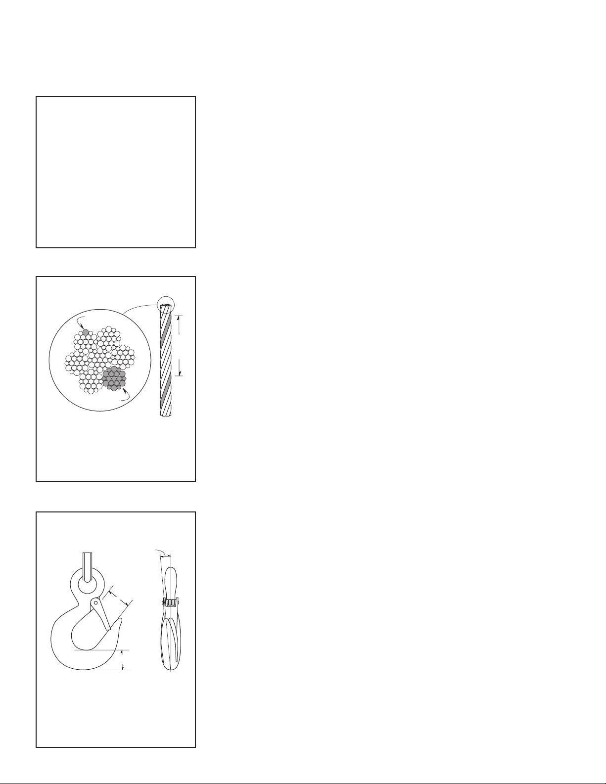
Figure 7 – Load Hook
Inspection
throat
opening
twist
thickness
The wire rope assembly must be
replaced if the throat opening is
15% wider than nominal, if the
thickness is 10% less than nomi-
nal, or if the hook is twisted 10° or
more.
Figure 6 – Broken Wires
wire
strand
one
lay
Wire rope assembly must be re-
placed if more than 6 wires are
broken in one lay, or if more than
3 wires are broken in one strand
in one lay.
Owner's Manual for Model 465 Worm Gear Hand Winch page 13
A5368F-0218
Table 2 – Troubleshooting Chart
Contact the factory for detailed instructions if you are required to disassemble the winch for any reason.
Disassembly before contacting Thern, Inc. voids all warranties.
problem cause correction
handle turns, drum doesn't turn •looseorbrokenspringpins .................inspectwinchandbrake,repairasnecessary
•loose,strippedorbrokengears ..............inspectgearsandrepairasnecessary
handle turns hard or not at all •loadtooheavy ...........................lightenload
•gearscontaminatedwithdirtanddebris........cleanandrelubricateasnecessary
•capscrew(drumshaft)bentorbroken .........inspectandreplaceasnecessary
•gearsbrokenorlocked.....................inspectandreplaceasnecessary
excessively warn gears •loadtooheavy ...........................lightenload
•poorlubricationofgears....................inspectandrelubricateasnecessary
overheating •operatedtoolongwithoutrest ...............allowtocool
•loadtooheavy ...........................lightenload
•poorlubrication...........................inspectandlubricateasnecessary
unusual noises
highpitchedsqueak •poorlubrication...........................inspectandrelubricateasnecessary
grindingnoise •contaminatedlubrication ...................cleanandrelubricatewinch
•dirtinwinchgears ........................inspectandcleanasnecessary
•brokengearsordrum ......................inspectandreplaceasnecessary
rattlingnoise •loosebolts,setscrewsorotherfasteners ......tightenallboltsandotherfasteners
f TEST WINCH PERFORMANCE by operating the winch with a load equal
to the load rating.
• Listen for unusual noises, and look for signs of damage as you operate the
winch.
• Make sure the wire rope winds evenly and tightly onto the drum. If it is
loose or uneven, rewind it before continuing.
• Make sure the handle rotates freely in both directions.
• Make sure the load moves smoothly, without hesitation or strain..
Completely correct all problems before continuing. Use the troubleshooting
chart to help determine the cause of certain problems. See Table 2.
Figure 8 – Rope Diameter
diameter
incorrect
correct
The wire rope assembly must be
replaced if the diameter measures
less than the minimum diameter at
any point.
wire rope
diameter minimum diameter
1/8in 7/64in(.1094in)
3/16in 11/64in(.1719in)
465 Worm Gear Hand Winch – Congurations and Performance Characteristics 2
loadrating(lb)wireddrumcapacity(ft)1 approx.
model3 1st mid full rope 1st mid full gear ship
number description layer drumdrumdia.(in) layer drum drum ratio wt.(lb)
465 750lb–marineduty 750 600 400 1/8 7 58 130 — 12
(recommendedforpullingonly) 3/16 4 27 59
PleasecontactfactoryornearestThernDistributorforrmxedpriceanddelivery.
1 Actualdrumcapacitiesmaybe25-30%less,duetononuniformwinding.Wireropetensionwillalsoaffectdrumcapacity.
2 PerformanceCharacteristicsareforstandardproductsreferredtointhismanual.Non-standardproductsmayvaryfromtheoriginal
design.ContactThern,Inc.forthisinformation.
3ModelsendingwithaVhaveframesrotated90degrees.

Owner's Manual for Model 465 Worm Gear Hand Winchpage 14
A5368F-0218
Important!
• It is your responsibility to de-
termine when to replace parts.
When considering whether to
continue using a part or to replace
it, remember that replacing it
is the best way to avoid further
equipment damage.
• Replace all spring pins and
retaining rings when you disas-
semble the winch or brake for
repair or replacement.
• Appoint a qualied person to be
responsible for all repairs to the
equipment.
3.4 Repairing the Winch
3.4.1 GET FACTORY AUTHORIZATION for all repairs. Unauthorized repairs
will void the warranty, and may lead to damage or failure of the winch.
3.4.2 REPLACE DAMAGED OR POORLY OPERATING PARTS with Thern
repair parts.
3.4.3 REFINISH AREAS where the paint is worn or aking. A good nish helps
to protect against corrosion and weather damage.
a REMOVE THE FINISH from damaged areas, down to the bare metal.
b CLEAN THE AREA thoroughly.
c REPAINT with a high quality primer and nishing coat.
3.4.4 TO ORDER REPAIR PARTS, contact your local dealer. Include the fol-
lowing information when ordering:
• model number
• serial number (or code number)
• part number
• date purchased, and from whom
• description of what happened, or what is wrong
• your name and return address
4.1 Transporting the Winch
4.1.1 PACK THE WINCH using the original packaging materials, if possible.
4.1.2 SEAL THE WINCH in plastic with a desiccant to help protect it from rust,
corrosion, and other damage.
4.1.3 INSPECT THE WINCH according to section 3.3 Inspecting the Equipment
before installing it in a new location.
4.2 Storing the Winch
4.2.1 SEAL THE WINCH in plastic with a desiccant to help protect it from rust,
corrosion, and other damage.
4.2.2 STORE THE WINCH in a cool clean place away from corrosive chemicals
and moisture.
4.2.3 ROTATE THE DRUM periodically to keep bearing and gear surfaces from
becoming lacquered.
4.2.4 INSPECT THE WINCH according to section 3.3 Inspecting the Equipment
before installing it for operation.
4.2.5 LUBRICATE THE WINCH PROPERLY prior to operation. See section 3.2
Lubricating the Winch.
Important!
• Keep a record of what you ship,
and when you send it.

Owner's Manual for Model 465 Worm Gear Hand Winch page 15
A5368F-0218
NOTES:

Owner's Manual for Model 465 Worm Gear Hand Winchpage 16
A5368F-0218
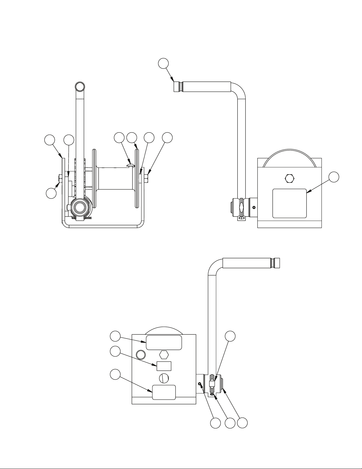
Worm Gear Hand Winch Models 465
item description part number qty.
1 FRAME A1459 1
2 BRACKETMACHINING B1050 1
3 MACHSCRTRSHDNYLK.250-20NCX.500ZNPL A1122 1
4 DRUMMACHINING A1113 1
5 SPACER A1119 1
6 CAPSCREWHEXHD.375-16NCX6.000ZNPLGR5 A3520 1
7 NUTHEXJAM2WAYLK.375-16NCZNPLGRDB A3576 1
8 SETSCRSQHD.312-18NCX.500ZNPLSTL A3724 1
9 PINSLOTTEDSPRING.187X1.250STL A2849 1
10 PINCOTTER.125X1.000STLSNPL A3179 1
11 SOCKETMACHINING462,465,472,9040 A1457 1
12 DRIVESHAFT A1460 1
13 HELICALGEARMACHINING A1118 1
14 WORM A1461 1
15 PINSLOTTEDSPRING.187X1.125STL A4041 1
16 HANDLEASSY462,465,472,MB441,9001,9008 B1038 1
17 MACHINEBUSHING A3906 1
18 LABELMODEL/CAPACITY465 A7528 1
19 LABELDATEOFMANUFACTURE 10477 1
20 LABELCAUTIONTHISUNITISNOTFACTORY A2175 1
21 LABELWARNING A1978 1
12 14 15
13
17
Owner's Manual for Model 465 Worm Gear Hand Winch page 17
A5368F-0218
9 10
8
11
18
19
20
21
356
1 2 4
16
7

Owner's Manual for Model 465 Worm Gear Hand Winchpage 18
A5368F-0218
Worm Gear Hand Winch Models 465V
item description part number qty.
1 FRAME A1459 1
2 BRACKETMACHINING B1050 1
3 MACHSCRTRSHDNYLK.250-20NCX.500ZNPL A1122 1
4 DRUMMACHINING A1113 1
5 SPACER A1119 1
6 CAPSCREWHEXHD.375-16NCX6.000ZNPLGR5 A3520 1
7 NUTHEXJAM2WAYLK.375-16NCZNPLGRDB A3576 1
8 SETSCRSQHD.312-18NCX.500ZNPLSTL A3724 1
9 PINSLOTTEDSPRING.187X1.250STL A2849 1
10 PINCOTTER.125X1.000STLSNPL A3179 1
11 SOCKETMACHINING462,465,472,9040 A1457 1
12 DRIVESHAFT A1460 1
13 HELICALGEARMACHINING A1118 1
14 WORM A1461 1
15 PINSLOTTEDSPRING.187X1.125STL A4041 1
16 HANDLEASSY462,465,472,MB441,9001,9008 B1038 1
17 MACHINEBUSHING A3906 1
18 LABELMODEL/CAPACITY465 A7528 1
19 LABELDATEOFMANUFACTURE 10477 1
20 LABELCAUTIONTHISUNITISNOTFACTORY A2175 1
21 LABELWARNING A1978 1
13
12
14 15
17

Owner's Manual for Model 465 Worm Gear Hand Winch page 19
A5368F-0218
18 19
20
8
11
10
9
1 2
3
456
7
21
16

Thern, Incorporated
5712IndustrialParkRoad
Winona,MN55987
PH507-454-2996
FAX507-454-5282
EMAIL:[email protected]
www.thern.com
Thern Europe
BedrijvenparkTwente454e
7602KMAlmelo
TheNetherlands
PH:+31-546-898-380
EMAIL:[email protected]
Thern
Winches & Cranes
Other Thern Winch manuals


Popular Winch manuals by other brands


Come.up Winch
Come.up Winch Seal Slim 12.5 quick start guide

Warn Industries
Warn Industries VRX 25-S Basic guide

Wedge Clamp Systems Inc.
Wedge Clamp Systems Inc. EZE ROLLER Assembly instructions

Cycle Country
Cycle Country 25-5070 installation instructions

Comeup
Comeup CP-250 quick start guide

Kangaroowinch
Kangaroowinch 2000 instruction manual