BRADEN HP100B Manual

1
HP100B
HYDRAULIC RECOVERY WINCH
INSTALLATION, MAINTENANCE, AND SERVICE MANUAL
LIT2580 Rev 2
August 2015
Printed in USA
}
First 2 numbers indicate
year manufactured
WRITE HOIST SERIAL NUMBER BELOW
For serial number location see page 4

2
TABLE OF CONTENTS
FOREWORD ...............................................................................................................3
GENERAL SAFETY RECOMMENDATIONS ..............................................................4
THEORY OF OPERATION..........................................................................................6
WINCH INSTALLATION ..............................................................................................8
HYDRAULIC CIRCUIT ..............................................................................................10
WIRE ROPE INSTALLATION.................................................................................... 11
PRE-DELIVERY CHECK LIST ..................................................................................12
WINCH OPERATION ................................................................................................12
DRUM CLUTCH OPERATION ..................................................................................14
AUXILIARY RIGGING ...............................................................................................16
PREVENTIVE MAINTENANCE.................................................................................17
RECOMMENDED PLANETARY GEAR OIL..............................................................19
TROUBLESHOOTING ..............................................................................................20
SERVICE PRECAUTIONS........................................................................................23
RECOMMENDED BOLT TORQUE ...........................................................................23
WINCH DISASSEMBLY ............................................................................................24
HP100B TOP LEVEL ASSEMBLY .............................................................................26
PRIMARY PLANETARY CARRIER SERVICE ..........................................................32
SECONDARY PLANET CARRIER SERVICE...........................................................34
OUTPUT PLANET CARRIER SERVICE...................................................................36
OVERRUNNING CLUTCH SERVICE .......................................................................38
MOTOR GROUP DIAGRAM .....................................................................................40
WARNING – This emblem is used to warn against haz-
ards and unsafe practices which could result in severe
personal injury or death if proper procedures are not
followed.
CAUTION – This emblem is used to warn against po-
tential or unsafe practices which could result in person-
al injury or product or property damage if proper proce-
dures are not followed.
CAUTION
Safety Informational callouts used in this manual include:

3
FOREWORD
Read and understand this manual before operating or servicing your BRADEN winch. Retain this manual for future
reference.
The minimum service intervals specied are for the operating hours of the prime mover.
This manual contains installation, operation and preventive maintenance instructions for most current model BRADEN
Planetary Recovery winches. As there are many product variations, you must become familiar with your BRADEN winch
to fully benet from the information contained within this publication.
Some illustrations in this manual may show details or attachments that may be different from your winch, and some
components may be removed for illustrative purposes.
Whenever a question arises regarding your BRADEN winch or this manual, please contact your nearest BRADEN dis-
tributor or the PACCAR Winch Technical Support Department at:
Telephone- 1-918-251-8511
08:00-16:30 Central Time Zone, Monday thru Friday
FAX- 1-918-259-1575
www.paccarwinch.com
Provide the complete winch model and serial number when making inquiries.
Parts and Service
BRADEN provides parts and service through a network of BRADEN distributors. Parts and service are not available
directly from the PACCAR Winch. For the name of your nearest BRADEN distributor, consult your local phone directory,
or contact BRADEN as described above.
EXPLANATION OF MODEL NUMBER
HP 100 B - 123 114/051 - 01 RA
HP DESIGNATES HYDRAULIC PLANETARY RECOVERY WINCH
100 DESIGNATES 100,000 POUND ( KG) FIRST LAYER LINE PULL
B DESIGNATES THE MODEL SERIES RELATING TO DESIGN CHANGES
123 DESIGNATES TOTAL GEAR RATIO (123:1)
114/051 DESIGNATES HYDRAULIC MOTOR DISPLACEMENT:
- 1.14 CUBIC INCH PER REVOLUTION LOW SPEED
- 5.10 CUBIC INCH PER REVOLUTION HIGH SPEED
01 DESIGNATES THE DRUM OPTION
RA (RIGHT HAND ASSEMBLY) - DESIGNATES THE SIDE OF THE TRUCK BED (VIEWED
UNIT IDENTIFICATION
When information is needed, always refer to
the model number and serial number. Both
are located on the top portion of brake cylin-
der assembly
MODEL NUMBER
AND
SERIAL NUMBER

4
GENERAL SAFETY RECOMMENDATIONS
Safety for operators and ground personnel is of prime con-
cern. Always take the necessary precautions to ensure the
safety of others as well as yourself. To properly ensure
safety, the prime mover and winch MUST be operated with
care and concern by the operator for the equipment. The
operator MUST also have a thorough knowledge of the
machine’s performance capabilities.
1. Read and understand ALL warning tag information,
and become familiar with ALL controls BEFORE op-
erating the winch.
2. NEVER attempt to clean, oil or perform maintenance
on a machine with the engine or prime mover running,
unless instructed to do so in this manual.
3. NEVER operate the winch controls unless you are
properly positioned at the operator’s station, you are
sure ALL personnel are clear of the work area AND
you are properly trained in the operation of the winch.
4. Assure that personnel who are responsible for hand
signals are clearly visible and that the signals to be
used are thoroughly understood by all involved.
5. Ground personnel should stay in view of the operator
and clear of the winch drum. DO NOT allow ground
personnel near a winch line under tension. A safe
distance of at least 1½ times the length of the out-
stretched cable should be maintained.
6. On machines having hydraulically, mechanically and/
or cable controlled equipment or attachments, ensure
the equipment is blocked securely before servicing,
adjusting or repairing the winch. ALWAYS apply the
parking brakes before dismounting a vehicle.
7. Inspect the winch and rigging at the beginning of each
work shift. Defects should be corrected immediately.
DO NOT operate a defective winch.
8. Keep equipment in good operating condition. Perform
scheduled service and adjustments as dened in the
“Preventive Maintenance” section of this manual.
9. An equipment warm-up procedure is recommended
for all start-ups, and is essential at ambient tempera-
tures below +40°F (5°C). Refer to the “Warm-Up Pro-
cedure” listed in the “Preventive Maintenance” section
of this manual.
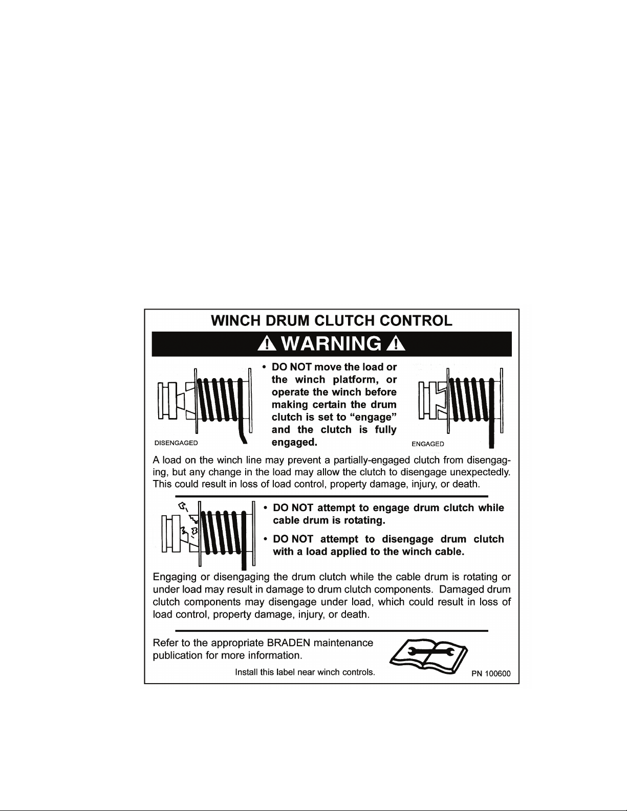
10. Check the drum clutch to be certain that the negative
draft angle is clearly evident on the clutch and clutch
plate. DO NOT use the winch if the negative draft
angles are worn straight, or if the edges of the clutch
plate are rounded or chipped.
11. External clutches on recovery winches may disengage
and drop or lose control of a load if they are NOT fully
engaged at the beginning of a lift or pull. The winch op-
erator must visually determine that the clutch is fully
engaged before lifting or pulling a load.
12. The winches described in this manual are neither de-
signed nor intended for use or application to equip-
ment used in the lifting or moving of persons.
13. DO NOT exceed the maximum pressure, PSI (kPa), or
ow, GPM (LPM), stated in the winch specications.
14. Operate the winch at line speeds to match the job con-
ditions.
15. Protective gloves should be worn when handling wire
rope.
16. NEVER attempt to handle wire rope when the hook
end is not free. Keep all parts of body and clothing
clear of cable rollers, cable entry area of fairleads and
winch cable drum.
17. When winding wire rope on the cable drum, NEVER
attempt to maintain tension by allowing the wire rope
to slip through hands. ALWAYS use the “Hand-Over-
Hand” technique.
18. NEVER use wire rope with broken strands. Replace
damaged wire rope.
19. DO NOT weld on any part of the winch without ap-
proval of PACCAR Winch Division Engineering.
20. Use the recommended hydraulic oil and gear lubri-
cant.
21. Keep the hydraulic system clean and free of contami-
nation at all times.
22. Use the correct anchor for the wire rope and pocket in
the drum. DO NOT use knots to secure or attach the
wire rope to the drum or hook.
23. The cable anchor or ferrule is NOT intended to support
full rated load. ALWAYS maintain a minimum of ve
(5) wraps on the drum. It is recommended the last ve
(5) wraps of wire rope be painted bright red to serve as
a visual reminder.
24. Install guarding to prevent personnel from getting any
part of body or clothing caught at a point where the ca-
ble is wrapped onto the drum or drawn through guide
rollers or other “pinch points”.
25. Install switches or valves that will shut off power to the
winch, in locations where they can be reached by any-
one entangled in the wire rope before being drawn into
the winch drum or other “pinch point”.
26. “Deadman” controls, which automatically shut off pow-
er to the winch whenever the operator leaves his sta-
tion, should be installed whenever possible.
Failure to obey the following safety recommendations
may result in property damage, injury, or death.

5
27. NEVER allow anyone to stand or position any part of
his or her body under a suspended load.
28. Avoid sudden “shock” loads, or attempting to “jerk”
a load free. This type of operation may cause heavy
loads, in excess of rated capacity, which may result in
a failure of the wire rope and/or the winch.
29. Whenever possible, install the winch in a location that
is not immediately adjacent to a “normal” operator’s
station.
30. ALL winch controls should be located within easy
reach of the operator. The controls shall be installed
in such a location that the operator is removed from
the electrical path to ground if the load, rigging or wire
rope comes into contact with or within proximity to an
electrically energized conductor.

6
BASIC DESCRIPTION
The winch consists of the following sub-assemblies:
1. Hydraulic motor and brake valve
2. Planetary gear reducer assembly
3. Static brake system
4. Cable drum, drum shaft and clutch
5. Base
The primary sun gear is directly coupled to the hydrau-
lic motor by the inner race of the brake clutch assembly.
The primary sun gear shaft goes through the drum and
drives the primary planet gears on the support end of the
winch. As the motor shaft turns in the haul-in direction,
the planetary assemblies reduce the speed input by the
motor to rotate the cable drum. In the haul-in direction,
the static brake remains fully applied and the input shaft
rotates freely through the sprag clutch. When the motor is
stopped, the load attempts to rotate the winch gear train
in the opposite direction locking the brake clutch to the
input shaft, allowing the fully applied static brake to hold
the load rm.
DUAL BRAKE SYSTEM
The dual brake system consists of a dynamic brake sys-
tem and a static brake system.
The dynamic brake system has two operating compo-
nents:
1. Brake Valve Assembly
2. Hydraulic Motor
The brake valve is basically a counterbalance valve with
better metering characteristics for load control. It contains
a check valve to allow free oil ow to the motor in the haul-
in direction, and a pilot operated, spring-loaded spool
valve that blocks the ow of oil out of the motor when the
control valve is placed in neutral. With the control valve
lever moved toward the pay-out direction, the spool valve
remains closed until sufcient pilot pressure is applied to
the end of the spool to shift it against the spring pressure
and open a passage. After the spool valve cracks open,
the pilot pressure becomes ow dependent and modulates
the spool valve opening, controlling the pay-out speed of
the winch. See Figures 1, 2, and 3.
The winch brake system has three main components for
all winches:
1. Spring-Applied, Multiple Friction Disc Static Brake
2. Hydraulic Piston and Cylinder
3. Brake Clutch Assembly
The static brake is released by the brake valve pilot pres-
sure at a pressure lower than that required to open the
pilot operated spool valve. This sequence ensures that dy-
namic braking takes place within the brake valve, and that
little, if any, heat is absorbed by the static, friction brake.
The static friction brake is load holding brake only, and has
nothing to do with dynamic braking or the rate of descent
of a load.
The brake clutch assembly is splined to the primary sun
gear shaft between the hydraulic motor and primary sun
gear. It will allow this shaft to turn freely in the direction
to haul-in a load, and locks up to force the brake discs to
turn with the shaft in the pay-out direction. See Figures 4
and 5.
The hydraulic brake cylinder, when pressurized, will re-
lease the spring pressure on the brake discs, allowing the
discs to turn freely.
THEORY OF OPERATION

7
Motor
Control Valve
Pump
To Tank
Brake Valve
Static Brake
Medium
Pressure
Low
Pressure
High
Pressure
Figure 1 REELING-IN
Figure 2 REEL-OUT - BEFORE BRAKE VALVE OPENS
Figure 3 REELING-OUT
Motor
Control Valve
Pump
To Tank
Brake Valve
Static Brake
Medium
Pressure
Low
Pressure
High
Pressure
Motor
Control Valve
Pump
To Tank
Brake Valve
Static Brake
Medium
Pressure
Low
Pressure
High
Pressure
Figure 5
Static Friction Brake Applied
Load attempts to rotate shaft in opposite direction
Brake clutch locks sun gear shaft to friction brake
Stopped,
Holding
Load
Sprag Cams
Figure 4
Static Friction Brake Applied
Permits free shaft rotation while hoisting
Hoisting
Sprag Cams

8
WINCH INSTALLATION
HP Series winches are congured for bed mount on a
truck. A right hand assembly (RA) has the motor end to
the passenger side of the vehicle and the wire rope over-
wound on the drum. A left-hand assembly (LA) has the
motor on the driver’s side with wire rope overwound on
the drum.
Headache racks or other protective structures designed
to protect the winch, truck, cab, and vehicle occupants
should be designed to enable easy access and servic-
ing of the winch. Braden recommends using a structure
designed to be easily removed should the need arise to
disassemble the winch for servicing.
1. A tank line for the hydraulic motor case drain is re-
quired from the shift block tee tting on the two-speed
motor or from the case drain on the single speed mo-
tor. See Step 6 for details.
2. The winch must be mounted to a at, rigid surface
which will not ex under load. The mounting surface
must be at within .020 in. (.05 mm) between mount-
ing fasteners. If necessary, use shim stock to ensure
proper mounting.
3. The centerline of the cable drum must be horizontal
and mounted perpendicular to the direction of pull. The
eet angle, or the angle created from an imaginary line
from the center of the cable drum to the load or rst
sheave and from this load point back to the drum bar-
rel intersection with the drum ange, must not exceed
1½°. Fleet angles in excess of 1½° will create uneven
spooling resulting in rapid drum or wire rope wear.
4. Grade 8, or better, fasteners are recommended for
mounting fasteners.
5. The winch base angles must be mounted securely to
the vehicle frame in a manner acceptable to the ve-
hicle manufacturer. Any frame adapter brackets used
should be bolted to the winch base angles as close to
the gear housing and bearing leg assemblies as pos-
sible. This will ensure the greatest strength while mini-
mizing distortion. Consult vehicle manufacturer before
making any modications to the vehicle frame.
6. Hydraulic lines and components to operate the winch
should be of sufcient size as to minimize the back-
pressure at the hydraulic motor work ports.
For conventional gear type motors, backpressure at
full ow should NOT exceed 100 PSI (690 kPa) for
maximum motor shaft seal life. If high backpressures
are encountered, the motor case drain can be con-
nected direct to the reservoir. For backpressures in
excess of 100 PSI (690 kPa), contact PACCAR Winch
Technical Support.
Winches equipped with Rineer 2-speed vane type or
piston type motors MUST be limited to 35 PSI (240
kPa) backpressure.
7. The winch directional control valve MUST be a three-
position, four-way valve without detents and with a
spring-centered motor spool, such that the valve re-
turns to the center (Neutral) position whenever the
handle is released, and both work ports are opened to
tank (open center, open port).
8. The hydraulic oil lter should have a 10 micron nomi-
nal rating and be a full-ow type.
9. High quality hydraulic oil is essential for satisfactory
performance and long hydraulic system component
life.
Hydraulic oils having a viscosity of 150 – 300 SUS @
100°F (30 – 56 cSt @ 40°C) and a viscosity index (VI)
of 100 or greater will provide good results under normal
temperature condition. The use of oil having a high VI will
minimize cold start-up problems and reduce the length of
warm-up periods. A high VI will also minimize changes in
viscosity with corresponding changes in temperature.
NOTE: For MAGNUM series winches equipped with
Rineer vane type hydraulic motors, the hydraulic oil se-
lected MUST remain above 100 SUS @ 100°F (20 cSt @
40°C) at all operating temperatures.
Flexing or uneven mounting surfaces will produce in-
ternal winch distortion which may result in rapid com-
ponent wear, overheating, poor winch performance
or an improperly engaged drum clutch which may be-
come disengaged and result in dropped loads or loss
of load control causing property damage, severe injury
or death.
DO NOT use a control valve with any detents or latch-
ing mechanism that will hold the control valve in an ac-
tuated or running position when the operator releases
the control lever. Use of the wrong type of control valve
could lead to unintentional operation of the winch, which
could result in property damage, injury or death.
Failure to install a case drain line of adequate size will
result in a blown out shaft seal on the hydraulic motor
and the winch will ll with hydraulic oil.
CAUTION

9
Maximum cold weather start-up viscosity should not ex-
ceed 5000 SUS with a pour point of at least 20°F (11°C)
lower than the minimum expected temperature.
Under continuous operating conditions the temperature of
the oil at any point in the system should not exceed 180°F
(82°C). 120°-140°F (49°-60°C) is generally considered
optimum.
In general terms; for continuous operation at ambient tem-
peratures 50°-110°F (10°-43°C), use SAE 20W; for con-
tinuous operation at 10°-90°F (-12°-32°C), use SAE 10W;
and for applications at ambient temperatures below 10°F
(-12°C), contact the PACCAR Winch Technical Support
Department. NOTE: The use of multi-viscosity oils is gen-
erally not recommended.
10. Maximum air pressure of 130 psi for clutch and brake
air cylinders.

10
2-Speed Hyd. Motor Sub-Assy Control Circuit
(”A” Port To ward Flange)
ITEM 7
WINCH
BRAKE
LOWER ITEM 13
CASE DRAIN
(CUSTOMER)
HOIST
BRAKE
VALVE
CHECK
VALVE
12V DC
SOLENOID
2-SP HYD MOTOR
2 - SPEED
SELECTOR
VALVE
P
T
TA
G
P2
P1
BR
BA
TYPICAL HYDRAULIC CIRCUITS
NOTE: The hydraulic circuits shown below are representative of typical HP100B winches with single and two-speed
hydraulic motors and brake valves. Options and accessory equipment may result in changes to the circuits dened.
If there are any questions regarding the hydraulic circuit, refer to the information supplied by the original equipment
manufacturer, or contact the PACCAR Winch Technical Support Department, as previously dened. (ALWAYS have the
winch model and serial number available when contacting PACCAR Winch.)
Two Speed
30 85 86 87 87A
Electric Shift Circuit
Hella 87499 Relay
(or equivalent -
12 Volt DC,
40 Amp, SPDT)
+12 VDC Power
Normally Open SPST Switch*
(Engaging Switch Shifts Motor
to High Speed) Motor
Solenoid
* DO NOT use a
momentary contact
switch. This type of
switch will return to the
open position when
released, shifting the
motor back to low speed.
1. Ground
2. Empty
3. Apply 12V DC power to shift
motor to High Speed
NOTE:
Terminals 1 and 3
may be reversed.
X
BRAKE
BR
DR
CONTROL
PUMP
WINCH ASSEMBLY
W/BRAKE VALVE
& STATIC BRAKE
WINCH
WINCH CONTROL CIRCUIT
EXTERNAL CASE DRAIN REQ’D
BRAKE
VALVE
VALVE
Single Speed
WINCH CONTROL CIRCUIT
EXTERNAL CASE DRAIN REQ’D
WINCH CONTROL CIRCUIT
EXTERNAL CASE DRAIN REQ’D

11
WIRE ROPE INSTALLATION
Winches are rated at bare drum line pull, meaning the maximum load capability will be reached on the rst layer of wire
rope. As the cable drum lls, the line pull will decrease (loss of leverage) as the line speed increases (larger circum-
ference). Therefore, it is best to install the minimum length of wire rope possible for your application so the winch will
operate on the lowest layers, delivering the maximum load capability.
Use of larger diameter wire rope will not always increase strength as the larger wire rope may be more prone to bending
fatigue failure due to the drum diameter. Consult your wire rope supplier for their recommendations regarding the best
wire rope and rigging for your application.
Winch wire rope anchors or ferrules are NOT intended to hold rated loads. Winch loads applied directly to the cable
anchor may cause the wire rope to pull free and result in sudden loss of load control and cause property damage,
injury or death. A minimum of ve (5) wraps of wire rope must be left on the drum barrel to achieve rated load.
INSTALLATION OF U-BOLT TYPE CLAMPS
Prepare the end of the wire rope as recommended by the wire rope manufacturer. Pass the wire rope through the U-bolt
until the end extends 1.5 – 2 wire rope diameters beyond the clamp. Evenly tighten the U-bolt nuts until the wire rope
deforms slightly under the U-bolt and the wire rope is securely held.
INSTALLATION OF SPIRAL FERRULES
Re-useable, eld installed spiral ferrules are available from PACCAR Winch Division or your wire rope supplier. These
ferrules are for use with six (6) strand, IWRC (Independent Wire Rope Core) type wire rope. Refer to cable capacity
specications on page 14.
Insert wire rope through the small diameter end of the
ferrule. Spread the strands and insert the spiral wedges
between the strands and the core. Lay the strands in the
individual grooves in the spiral wedges.
Tap the wedges and wire rope end into the ferrule, leav-
ing approximately 3/8 in. (10 mm) extending from the top.
The rst load applied to the winch will seat the wire rope
and wedges securely in the ferrule.
STEP ONE STEP TWO

12
PRE-DELIVERY CHECKLIST
Before releasing the winch to the end user, the following checklist should be reviewed and each item veried.
WINCH OPERATION
The following warnings and instructions are basic to safe
winch operation. Please read them carefully and follow
them any time the winch is in use. These instructions are
provided in addition to any information provided by the
Original Equipment Manufacturer. Equipment operators
should be completely familiar with the overall operation of
the vehicle to which the winch is installed. If you have any
questions concerning the safe operation of this winch or
the equipment to which it is mounted, contact the equip-
ment manufacturer that installed the winch, or the PAC-
CAR Winch Technical Support Department, as previously
described.
The winch directional control valve, described earlier,
controls haul-in and pay-out functions of the winch. Mov-
ing the control lever in the haul-in direction will cause the
winch to pull in the load toward the vehicle. Moving the
control lever in the pay-out direction will cause the winch
to feed wire rope off the drum.
Two-speed winches are equipped with a two-speed hy-
draulic motor and solenoid operated shift valve, elimi-
nating the need to add extra valves to allow two-speed
operation. A 12V DC toggle switch is required to actuate
the solenoid. The motors are spring-biased to low-speed
mode. Actuating the toggle switch will energize the sole-
noid, allowing pilot pressure to act on the shift spool in the
motor, shifting the motor to high-speed mode.
Ground personnel MUST stay in view of the operator
and clear of the load and cable drum at all times. DO
NOT allow personnel near the winch line while under
tension. DO NOT allow personnel near the cable drum
during winch operation. DO NOT allow personnel to be
in line with the load. DO NOT allow personnel to stand
under a suspended load. A safe distance of 1½ times
the working length of the cable should be maintained by
ground personnel. A broken wire rope and/or lost load
may cause property damage, injury or death.
Failure to properly warm up the winch, particularly un-
der low ambient temperature conditions, may result in
temporary brake slippage due to high back pressures
attempting to release the brake, which may result in
property damage, injury or death.
Failure to use the proper type and viscosity of planetary
gear oil may contribute to intermittent brake clutch slip-
page which could result in property damage, injury or
death. Some gear lubricants contain large amounts of
EP (extreme pressure) and anti-friction additives which
may contribute to brake slippage and damage to brake
friction discs or seals. Oil viscosity with regard to ambi-
ent temperature is also critical to reliable brake opera-
tion. Testing indicates that excessively heavy or thick
gear oil may contribute to intermittent brake slippage.
Make certain that the gear oil viscosity used in your
winch is correct for your prevailing ambient tempera-
ture.
INSPECTION X
Check gear oil and rell as needed
Lubricate all grease ttings
Inspect winch mounting fasteners and torque as required
Check for loose or missing bolts, pins, keepers, and cotter pins - replace as needed
Check controls - adjustment and operation
Verify winch operating pressure and ow
Verify proper brake band operation
Inspect for external oil leaks - repair as needed

13
NOTE: During typical winching operations, it is generally
recommended to operate the vehicle engine at high idle
RPM and use the winch control valve to control oil ow,
and thus winch line speed as needed.
Position the vehicle such that the centerline of the winch
drum is perpendicular to the winch load whenever pos-
sible. The wire rope eet angle must not exceed 1½°. If
the eet angle exceeds 1½°, the wire rope will not spool
correctly eventually resulting in damaged wire rope and
prematurely worn winch components.
Either power out the wire rope using the hydraulic system,
or disengage the drum clutch and pull the wire rope off the
drum by hand (freespool).
Securely attach the wire rope to the load in such a manner
as to avoid damaging the load or rigging. Fully engage the
drum clutch (see Drum Clutch Operation).
Ensure the band brake is released and engage the winch
control lever. Operate the winch controls smoothly to avoid
“jerking” the load and maintain good load control.
Observe the winch operation carefully to make certain all
ground personnel remain clear of the wire rope and load,
and that the load does not shift, which may require reposi-
tioning the wire rope or the vehicle.
Once the load is positioned properly, move the lever back
to neutral to stop the winch. Secure the load as required.
Pay out just enough wire rope to remove all tension on the
cable drum. Disengage the drum clutch and disconnect
the wire rope from the load.
Re-engage the drum clutch. Ensure the drum clutch is
fully engaged.
Wind the wire rope onto the cable drum while maintaining
the minimum eet angle and sufcient tension to allow the
wire rope to spool properly, being careful to keep hands
and clothing away from the cable drum and/or fairlead roll-
ers.
The band brake on the clutch end of the cable drum
is used to control drum overspin or “birdnesting” ONLY
when operating in freespool mode with the drum clutch
disengaged. DO NOT attempt to control any winch load
using the band brake. Attempting to control or hold any
load with the band brake may result in loss of load,
property damage, injury or death.
When operating the winch in the pay-out direction,
ALWAYS bring the load to a complete stop BEFORE
attempting to shift the motor into high speed mode.
“Shifting-on-the-y”, or attempting to shift while the load
is still moving, will result in pressure intensication be-
tween the brake valve and the hydraulic motor, which
can damage the motor, brake valve, or other hydraulic
components. Failure of these components may cause
loss of load control which could lead to personal injury
or death.

14
DRUM CLUTCH OPERATION
Visually ensure that the drum clutch is fully engaged and
the clutch control lever is at full travel or locked in its de-
tent BEFORE attempting to use the winch under load.
NOTE: Actuation of the drum clutch is typically accom-
plished using either air cylinder controls or some form of
mechanical control (i.e. push-pull cable, mechanical link-
ages, etc.). Any means used to control the drum clutch
must allow full travel of the lever without binding the clutch,
or should include locking detents at each position.
To ENGAGE the drum clutch:
1. Insure the winch motor is stopped and there is no load
on the wire rope. The prime mover must be stopped in
neutral and the parking brake must be set.
2. Move the clutch control lever fully into the “Engage”
position. If the lever will not settle into the fully engaged
position, the clutch is not fully engaged. At this point,
it may be necessary to MANUALLY rotate the cable
drum slightly in either direction to align the clutch lugs,
while continuing to hold slight pressure on the control
lever. Once the clutch lugs are properly aligned, the
clutch should easily engage fully with the clutch plate
on the cable drum.
To DISENGAGE the drum clutch:
1. Insure the winch motor is stopped and there is no load
on the wire rope. The prime mover must be stopped in
neutral and the parking brake must be set.
2. Move the control lever fully into the “Disengage” posi-
tion. If the control lever has any resistance to shift, the
cable drum may be MANUALLY rotated in the direction
to haul-in wire rope to relieve the self-energized load
on the clutch lugs and allow the clutch to properly dis-
engage.
NOTE: If your application involves lifting loads and does
not require the clutch to be disengaged, it is strongly rec-
ommended that the drum clutch be mechanically blocked
in the fully engaged position to avoid accidental disen-
gagement of the clutch under load.
DO NOT move the load, the winch, or the winch plat-
form BEFORE making certain the drum clutch is set to
“ENGAGE” and the clutch is fully engaged. A partially
engaged drum clutch may “jump out” of engagement. A
load on the winch line may prevent a partially engaged
clutch from disengaging, but any change in load condi-
tion may allow the clutch to become disengaged unex-
pectedly. This action may cause a loss of load control
which could result in property damage, injury or death.
Accidental disengagement of the clutch while lifting or
lowering may cause a loss of load control, which could
lead to property damage, injury or death.
DO NOT attempt to engage the drum clutch while the
cable drum is rotating. DO NOT attempt to disengage
the drum clutch with a load applied to the wire rope. DO
NOT use “cheaters” to extend the shift lever length or
other means to apply undue force on the lever. Engag-
ing or disengaging the drum clutch while the cable drum
is rotating or under load, or the use of undue force, may
result in damage to the drum clutch components. Dam-
aged drum clutch components may allow the drum
clutch to become disengaged under load, and cause a
loss of load control, which could result in property dam-
age, injury or death.

15
PROCEDURE FOR DETERMINING THE
CONDITION OF CLUTCH LUGS:
There is a “negative draft” angle on the load bearing faces
of the clutch and clutch plate to prevent clutch disengage-
ment under load. In addition to visual inspection of the
clutch surfaces, the following procedure may be used to
ensure that the clutch cannot inadvertently disengage un-
der load:
1. Fully engage the clutch (as previously described).
2. Power approximately 10 ft. (3 m) of wire rope off the
drum.
3. Power in very slowly while holding slight pressure on
the wire rope to eliminate any slack in the wire rope
and the power train. This slight pressure and no-slack
condition must be maintained throughout this proce-
dure.
4. Stop the winch with the clutch fully engaged, leaving
approximately 3 ft. (1 m) of wire rope extended beyond
the drum.
5. Mark one line on or near the tip of the drum ange
nearest the gear housing, and a second line on the
gear housing adjacent to the rst.
6. While maintaining tension on the wire rope, SLOWLY
disengage the drum clutch and observe the marked
lines. The drum ange should move 1/16 – 5/16 in.
(1.5 – 8 mm) in the haul-in direction. If the drum moves
LESS than 1/16 in. (1.5 mm), or if the drum rotates
in the opposite direction, the winch should be disas-
sembled and the clutch components visually inspected
for wear and/or damage and replaced as needed. The
drum clutch should be routinely inspected using this
procedure.
The Warning Label shown above is available through all Braden dealers. Have your
dealer order part number 100600. It is a self-adhesive weather-resistant vinyl label
that we recommend be installed near the winch controls of all Braden winches with
a drum clutch.

16
AUXILIARY RIGGING
Snatch Block
An auxiliary sheave, or snatch block, may increase the
versatility of the winch, and is highly recommended in the
following applications:
• When eet angles exceed 1½°.
• When winch loads exceed the safe winch or wire rope
capacity.
• When slower line speeds are required for precise load
control.
Securely attach the snatch block to the anchor point fol-
lowing the block manufacturer’s recommendations.
Tree Protector
If the wire rope or a snatch block must be anchored to a
tree or other structure for recovery purposes, a heavy ny-
lon web sling of proper capacity rating should be used to
avoid causing serious damage to the tree.
BRAKE END
OIL DRAIN
VENT
LOWERING
PORT
MOTOR DRAIN
TO TANK
BRAKE
ENGAGE
PORT
HOISTING
PORT
OIL FILL
OIL LEVEL
GEARBOX
OIL DRAIN
CLUTCH
DISENGAGE
PORT
CLUTCH ENGAGE
PORT
HAUL-IN
A poorly attached or undersized snatch block may
break loose from the anchor point and cause a sudden
loss of load control, which may result in property dam-
age, injury or death.
NOTES:
1. OIL CAPACITY: 12.5 PTS. (7.1 L) - TOTAL
(ONE PINT TO THE BRAKE END AND 11.5 PINTS TO THE GEAR END)
2. CABLE FERRULE SUPLIED WITH WINCH DESIGNED FOR 1.125 (1 1/8
INCH, 29mm) WIRE ROPE.
3. MAXIMUM AIR PRESSURE OF 130 PSI (9 BAR) FOR CLUTCH AND
BRAKE CYLINDER.

17
A regular program of preventive maintenance for your
winch is required to minimize the need for emergency ser-
vicing and will promote safe, reliable winch operation.
The user of PACCAR Winch products is responsible for
winch inspection, testing, operator training and the main-
tenance noted below, with frequency dependent on the
severity of the winch duty cycle and the thoroughness of
the preventive maintenance program.
Field experience, supported by engineering testing, indi-
cate the two service procedures listed below are the most
critical to safe, reliable winch operation and MUST be ob-
served.
• Regular Gear Oil Changes
• Use of Proper Gear Oil – recommended type for pre-
vailing ambient temperatures and additives.
Recommended Preventive Maintenance Intervals:
Daily (when winch is in use)
1. Inspect the wire rope and rigging for broken wires or
other damage, as recommended by the wire rope and
rigging manufacturer(s).
2. Carefully inspect the drum clutch and adjust the shift
mechanism as required to ensure the clutch can be
fully engaged and disengaged. (Refer to “Drum Clutch
Operation”.)
3. Check for external oil leaks – both hydraulic and gear
oil – and repair as required. This is extremely important
due to the accelerated wear that can be caused by in-
sufcient lubrication within the winch. Gear oil must be
maintained at the proper level. Use only recommended
lubricants. (See “Recommended Lubricants” in this
manual.)
4. Check hydraulic motor plumbing for damage, such as
chafed or deteriorating hoses, and repair as needed.
5. Visually inspect for loose or missing bolts, pins, keep-
ers or cotter pins, and tighten or replace as needed.
Weekly
1. Perform all daily inspections.
2. Check gear oil level, and rell as needed with the rec-
ommended lubricant.
3. Lubricate the grease ttings on the bearing leg, cable
drum ends and clutch. On some winches, you will have
to disengage the clutch to gain access to the drum
bushing grease tting on the clutch end of the drum.
Use a high-quality, moly-type grease, with a rating of
NLGI-2 or better.
4. Inspect the gear housing breather to ensure the tting
is not clogged with dirt or grease. Clean or replace as
needed.
5. Inspect all winch mounting fasteners. Retighten or re-
place as required.
6. Inspect any structural welds, and repair as needed.
Monthly
1. Perform all daily and weekly inspections.
2. Inspect the drum clutch and clutch plate to ensure the
negative draft angle is clearly evident. Replace worn
clutch components as required. (Refer to “Drum Clutch
Operation” in this manual.)
3. Check the hydraulic system relief valve setting to en-
sure proper performance and protection of hydraulic
components. Adjust or repair as required.
4. Inspect hydraulic system lters and strainers. Follow
the system manufacturer’s service recommendations
for repair or replacement.
5. Inspect the band brake for wear or chipping away of
the brake lining material. Adjust or replace as needed.
Yearly
1. Perform all daily, weekly and monthly inspections.
2. Replace gear oil.
NOTE: If the winch is used in excess of 40 hours per week,
the gear oil should be changed every 6 months.
NEVER attempt to service a winch with the prime mover
running as accidental engagement may result in prop-
erty damage, injury or death. Make certain ALL load
is removed from the wire rope and winch cable drum
BEFORE servicing the winch. A loaded wire rope may
rapidly and unexpectedly unspool, resulting in property
damage, injury or death.
PREVENTIVE MAINTENANCE
Hot oil can cause severe injury. Make certain the oil has
cooled to a safe temperature before servicing.
DO NOT use the winch if the negative draft angle on
the clutch is not present or is worn straight, or if the
clutch plate edges are rounded or chipped. A defective
drum clutch may suddenly become disengaged causing
a loss of load control, which may result in property dam-
age, injury or death.

18
Daily WeeklyMonthlyYearly
Inspect wire rope and rigging XXXX
Inspect drum clutch and shift
mechanism for
p
ro
p
er en
g
a
g
ement XXXX
Inspect for external oil leaksXXXX
Check for damaged hoses / lines XXXX
Check for loose or missing bolts,
p
ins
,
kee
p
ers
,
or cotter
p
insXXXX
Check gear oil level / refillXXX
Lubricate grease fittingsXXX
Inspect breather fitting XXX
Inspect winch mounting fasteners -
tor
q
ue as re
q
uiredXXX
Inspect structural weldsXXX
Inspect negative draft angle on drum
clutch and clutch
p
late XX
Check hydraulic relief valve setting XX
Inspect hydraulic filters / strainers XX
Re
p
lace
g
ear oil
(1) (2)
X
NOTES:
(1) Change the gear oil after the first 100 hours or 30 days of use,
whichever occurs first.
Inspection Interval
Inspection Performed
(2) For winch operation in excess of 50 hours per week, oil changes should
occur ever
y
6 months instead of
y
earl
y
.
SPECIFICATIONS

19
RECOMMENDED PLANETARY GEAR OIL
Field experience, supported by engineering endurance tests, indicates the use of the proper gear oil and a program
of regular preventive maintenance will help provide extended gear train life and reliable hoist brake performance. For
this reason, BRADEN has published the following specifications to assist in determining which lubricant is best suited
to your application.
For simplicity, BRADEN has listed available products in each temperature range that have been tested and found to
meet our specifications. This is not to say that other lubricant brands would not perform equally as well.
If the following lubricant brands are not available in your area, make certain your lubricant vendor supplies you with oil
equivalent to those products listed below.
Failure to use the proper type and viscosity of planetary gear oil may contribute to intermittent brake clutch slippage,
which could result in property damage, severe personal injury, or death. Some gear lubricants contain large amounts
of EP (Extreme Pressure) and anti-friction additives, which may contribute to brake clutch slippage or damage to
brake friction discs or seals. NOTE: DO NOT use oil that is labeled as meeting "API Service GL-5." Oil viscos-
ity, affected by ambient temperature, is also critical to reliable brake clutch operation. Our tests indicate excessively
heavy or thick gear oil may contribute to intermittent brake clutch slippage. Make certain the gear oil viscosity used
in your hoist is correct for your prevailing ambient temperature.
PREVAILING AMBIENT TEMPERATURE
oF -40 -30 -20 -10 0 10 20 30 40 50 60 70 80 90 100 110 120 130 oF
oC -40 -30 -20 -10 0 10 20 30 40 50 oC
SHADED TEMPERATURE RANGE IN THE CHART ABOVE NOT RECOMMENDED FOR SEVERE APPLICATIONS SUCH AS SUSTAINED
FAST DUTY CYCLES OR FREQUENT WINCHING.
TexacoShell
Meropa 220
Meropa 150
Omala S2 G 220
Omala S2 G 150
Chevron
Gear Compounds EP 220
Gear Compounds EP 150
PREVAILING AMBIENT TEMPERATURE
oF -40 -30 -20 -10 0 10 20 30 40 50 60 70 80 90 100 110 120 130 oF
oC -40 -30 -20 -10 0 10 20 30 40 50 oC
SHADED TEMPERATURE RANGE IN THE CHART ABOVE NOT RECOMMENDED FOR SEVERE APPLICATIONS SUCH AS
Mobil
Mobilgear 600 XP 220
Mobilgear 600 XP 150
Winches are factory filled with Mobilgear 600 XP 150 or equivalent. Consult your oil supplier for other equivalent
oils if required.
RECOMMENDED GEAR OIL
Omala S4 GX 150
Mobilgear SHC 150
Use gear oil detailed in Range A
Range A
Range B
Range C
Use gear oil detailed in Range B
Use gear oil detailed in Range C
Failure to properly warm up the winch, particularly under low ambient temperature conditions, may result in temporary
brake slippage due to high back pressures attempting to release the brake, which could result in property damage,
severe personal injury or death.
If you have any questions regarding this bulletin or your BRADEN planetary winch, please contact the
BRADEN Product Support Department at 1-918-251-8511, Monday through Friday
from 08:00 to 16:30 hours CST, or by fax at 1-918-259-1575.

20
TROUBLESHOOTING
TROUBLE PROBABLE CAUSE REMEDY
A
The winch will not reel-out the
load or not reel-out the load
smoothly.
1. The problem could be a plugged or
loose pilot orice. The pilot orice
is a small pipe plug with a hole
drilled through it, located behind
the pilot port tting on the brake
valve. If it becomes plugged, it will
prevent the pilot pressure, from
the manifold, from opening the
brake valve. If it becomes loose,
it will allow an unregulated amount
of oil in to operate the brake valve
which causes erratic brake valve
operation.
2. The friction brake may not be re-
leasing as a result of a defective
brake cylinder seal.
NOTE: If the brake cylinder seal is
defective you will usually nd oil leak-
ing from the winch vent plug.
3. Friction brake will not release as a
result of damaged brake discs.
Remove the pilot hose and tting from the
brake valve, then use a 5/32 inch Allen
wrench to remove the pilot orice. The di-
ameter of the orice is approximately .020
inches. Clean and install the pilot orice
tightly in the brake valve.
Check brake cylinder seal as follows:
A. Disconnect the swivel tee from the brake
release port. Connect a hand pump with ac-
curate 0-2000 psi gauge and shut-off valve
to the –4 J.I.C. tting in the brake release
port.
B. Apply 1000 psi to the brake. Close shut-
off valve and let stand for ve (5) minutes.
C. If there is any loss of pressure in ve (5)
minutes, the brake cylinder should be dis-
assembled for inspection of the sealing sur-
faces and replacement of the seals. Refer
to “Motor Support-Brake Cylinder Service”.
Disassemble brake to inspect brake discs.
Check stack-up height as described in “Mo-
tor Support-Brake Cylinder Service”.
B
Oil leaks from vent plug. 1. Same as A2.
2. Motor seal may be defective as a
result of high system back pres-
sure or contaminated oil.
Same as A2.
System back pressure must not exceed 150
psi. Inspect hydraulic system for a restric-
tion in the return line from the control valve
to the reservoir. Be sure control valve and
plumbing is properly sized to winch motor.
Ensure case drain line is connected and
adequate size.
Oil analysis may indicate contamination
has worn motor shaft and seal. Thoroughly
ush entire hydraulic system and install
new lters and oil. Install new motor seal.
Table of contents
Other BRADEN Winch manuals
Popular Winch manuals by other brands

TALBOT Industrie
TALBOT Industrie TA900 Use and maintenance

Dover
Dover TWG Tulsa 12-SLLRO Series Parts information

Winchmax
Winchmax WM13500 Fitting and Operating Guide

Comeup
Comeup CWS-80 quick start guide

Warrior Winches
Warrior Winches S2500EN owner's manual

Runva
Runva EWB9500 Assembly & operating instructions

POWERWINCH
POWERWINCH T1650 operating instructions

Ramsey Winch
Ramsey Winch Quick Mount 5000 owner's manual

Ramsey Winch
Ramsey Winch H-89 Maintenance manual

Miller
Miller ManHandler 8442/65FT User instruction manual

Comeup
Comeup GTD-650 manual

MSA
MSA SURE STRONG SCE1074021050 Instruction for operation and maintenance