B&G electronics DUAL-VOX LTC-06 User manual

Models:
LTC-06
LTC-06L
PLEASE READE BEFORE USING THE EQUIPMENT
EN 2.0
INSTALLATION AND OPERATION MANUAL
English

LTC LTC
2 3
COMPONENTS
Coupling
Connector
(to electronic unit)
External speaker
External microphone
Cable conduit
ON
OFF
SIREN
Switch
ON/ OFF/ Siren
Mode selector
· Manual (PTT)
· Auto (half-duplex)
Input selector
· Headset
· Speaker
Connection for customer
service recording (DAR)
Output (external unit connector)
Power adapter
Headset
Internal volume
External volume
Internal speaker
Internal microphone
with flexible neck
Push button
· MUTE (in auto mode)
· PTT (in manual mode)
LED indicator
· On
· Muted
· Manual mode
Power adapter
12V DC
External speaker
Model LTC-06
Internal Unit
External speaker
Model LTC-06L
Connector
(to electronic unit)
External
microphone
External
speaker
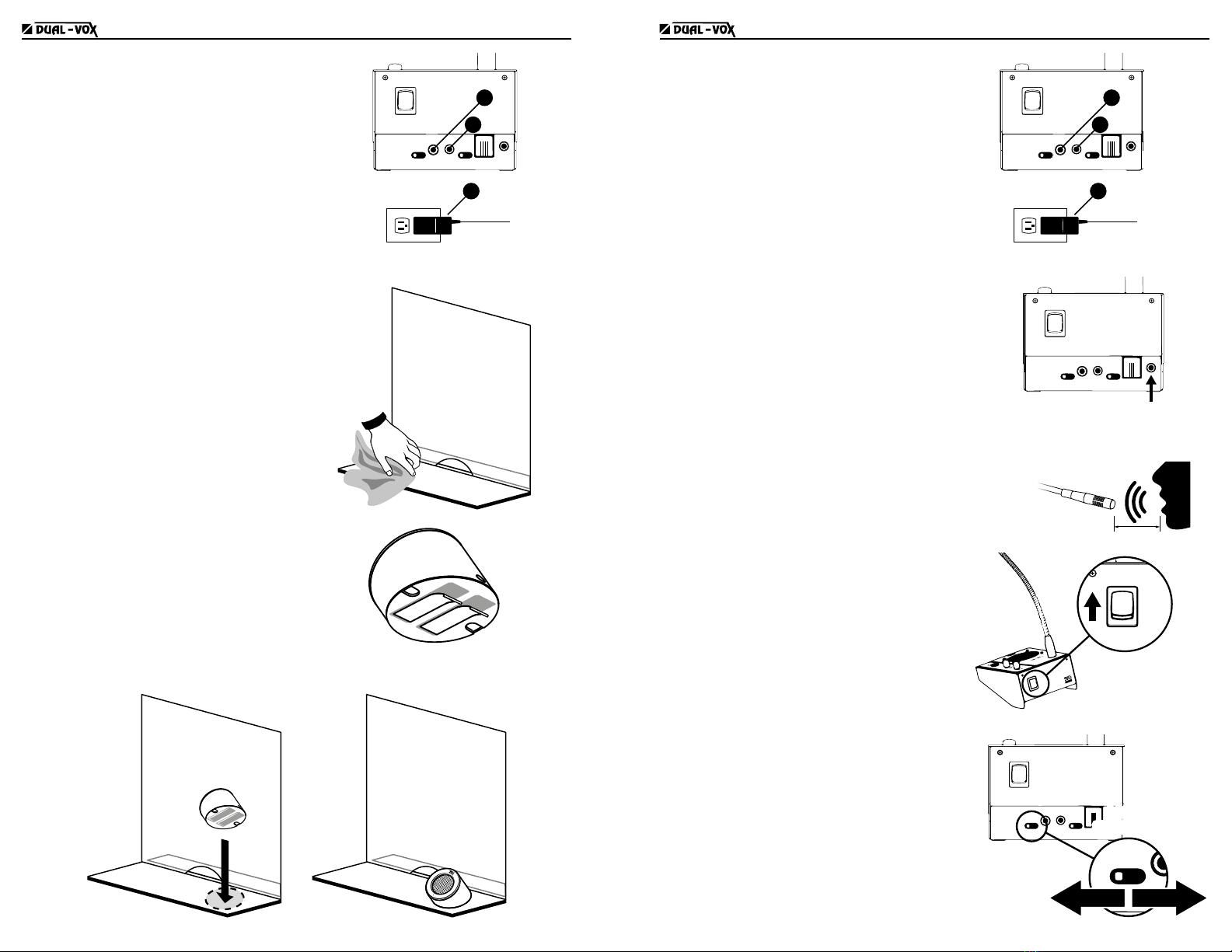
INSTALLATION LTC-06
(If your equipment model is LTC-06L, go to the next page)
Mounting the external speaker on glass
1. Clean the surface where the speaker is to be mounted
with alcohol to ensure a good adhesion.
2. Stick the mounting tapes to the back of
the speaker and remove the protective
layer from the tapes.
3. Secure the speaker to the glass by
pressing hard.
4. Pull the cable carefully to maximize its
length and to ensure a good presentation
of the installation without cable slack.
5. Tighten the upper end of the tube to the
speaker and the lower end to the coupling.
2
3
5
5
4
6. Apply glue to the surface of the coupling and stick to the glass.
Glass
7. Place the round sticker on the inner side of the glass, so
that the sticker covers the mounting tapes.
LTC LTC
4 5
8. Pass the cable from the external speaker
to the inner side of the barrier and
connect the speaker to the internal unit.
9. Connect the power adapter to the internal
unit and to the electrical outlet. The
equipment is now ready to be turned on.
ON
OFF
SIREN
8
9
9
100 - 240V AC
INSTALLATION LTC-06L
(If your equipment model is LTC-06, return to
the previous page)
1. Clean the surface where the speaker is
to be mounted with alcohol to ensure a
good adhesion.
2. Stick the mounting tapes to the bottom
of the speaker and remove the protective
layer from the tapes.
3. Secure the speaker to the desk by pressing hard.
4. Pass the cable from the external speaker
to the inner side of the barrier and
connect the speaker to the internal unit.
5. Connect the power adapter to the internal
unit and to the electrical outlet. The
equipment is now ready to be turned on.
ON
OFF
SIREN
8
9
9
100 - 240V AC
CONNECTION TO THE CUSTOMER SERVICE
RECORDING EQUIPMENT DAR-04
(complementary product)
DAR-04 (Digital Audio Recording) is a equipment that
complements the application of the DUAL-VOX.
Allows to record customer service conversations on a
continuous basis, according to the schedule dened
in the software.
ON
OFF
SIREN
DAR-04
OPERATION
Both units are equipped with microphone and speaker
to provide 2-way half-duplex communication (2-way
communication with one way at a time).
The recommended speaking distance to the internal
microphone is 5 to 10 cm.
5 - 10 cm
Switching on the equipment
Power on/off is controlled by a 3-position
switch on the back of the internal unit.
To turn the equipment on, pull the switch up to
its upper position.
To turn off the equipment, pull down the
switch to its central position.
LTC-06
ON
OFF
SIREN
ON
OFF
SIREN
Intercom modes
While the equipment is on, the exterior à interior
channel is permanently open, so that sounds from
outside are always heard on the internal side.
To control the opening of the interior à exterior
channel, the equipment has two operation modes:
automatic mode and manual mode.
The mode is changed from the sliding switch
located at the backside. Slide the switch to the
left position for automatic mode, and to the right
position for manual PTT mode.
ON
OFF
SIREN
MODE
SELECTOR
MODE
SELECTOR
OFF
SIREN
AUTOMATIC MANUAL PTT

LTC LTC
6 7
Automatic Mode
In this mode the equipment opens the interior à exterior channel
automatically when it detects voice in the internal microphone.
Whenever the teller speaks to the internal microphone, the
equipment switches to the interior à exterior channel, and when
the teller nishes speaking, the equipment switches back to the
exterior à interior channel.
In automatic mode the LED indicator is permanently on.
Mute
PTT
Auto
MUTE (Automatic Mode function)
The internal microphone can be muted so that the teller can speak
without being heard outside.
To mute the microphone press and release MUTE / PTT. While
MUTE is active the LED blinks at equal intervals.
To activate the microphone again, press and release MUTE / PTT.
PTT
Auto
Mute
Auto Mute (Automatic Mode function)
For high ambient noise environments the equipment has an automatic mute function, so
that the external microphone is automatically muted while the teller is not serving any
customers.
To activate Auto Mute press and hold MUTE / PTT until the LED
turns off, then release the button and you will hear 2 beeps
conrming that the function has been activated.
To deactivate Auto Mute repeat the procedure, when releasing
the button you will hear 1 beep conrming that the function was
deactivated.
PTT
Auto
Mute
While the Auto Mute function is active, the exterior à interior channel automatically closes
after 30 seconds of inactivity on the internal microphone, and reopens upon detecting
voice on the internal microphone or by pressing and releasing MUTE / PTT.
Manual Mode PTT (push-to-talk)
In this mode the equipment opens the interior à exterior channel
by pressing and holding MUTE / PTT, and closes it when the button
is released.
In PTT mode, the LED blinks in uneven intervals.
Auto
Mute
PTT
Emergency Siren Function
The equipment has a function to sound a siren in case
of emergency. It is controlled from the power switch
on the backside.
Pull down the switch to its lower position to activate
the siren.
To deactivate the siren, pull up the switch.
LTC-05
ON
OFF
SIREN
ON
OFF
SIREN
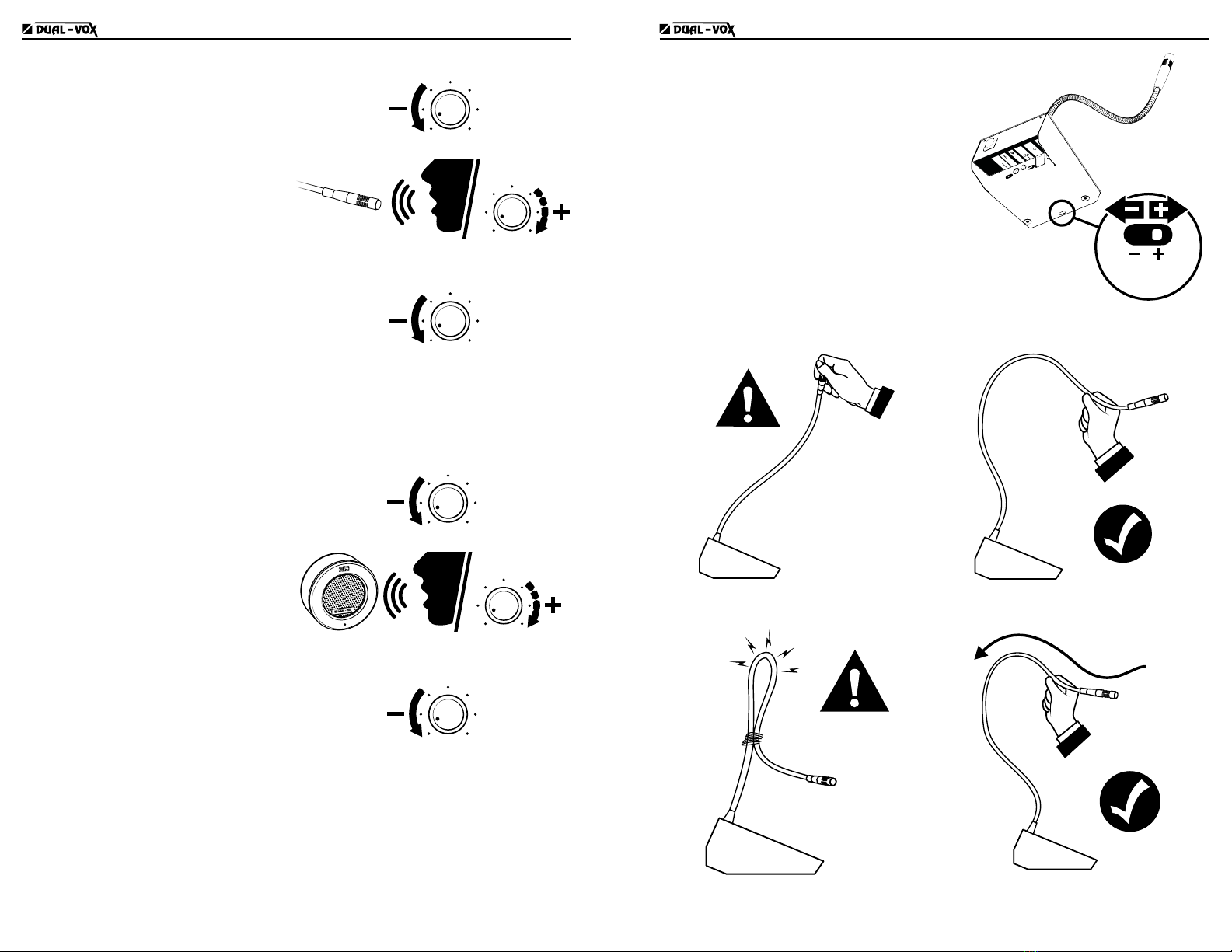
CONFIGURATION
Adjusting the internal volume
Use the Listen knob to adjust the volume at
which the customer’s voice is heard on the
inner side.
Listen
Volume
Adjusting the external volume
Use the Talk knob to adjust the volume
at which the teller’s voice is heard on the
external speaker.
Talk
Volume
Headset use (optional)
The equipment allows to connect a headset
with a incorporated microphone for the use
inside the barrier.
1. Connect the headset to the INPUT HDS
connector (RJ9).
2. Move the second sliding switch to its left
position, labeled HDS.
ON
OFF
SIREN
1
2
Calibration procedure
Once all the components are connected, perform the calibration procedure so that the
intercom operates optimally according to the sound insulation of the barrier and the
ambient noise of the location.
This procedure requires two people, one on the inside of the barrier and the other on the
outside.
Important note:For proper operation of the equipment is important to calibrate it to suit
the sound insulation of the barrier.
External sound calibration
1. Switch on the equipment in automatic mode (see “Automatic Mode” in “Intercom
modes”).
LTC LTC
8 9
2. Turn the external volume all the way
down (Talk knob).
Talk
Volume
3. While speaking to the internal
microphone, slowly increase the
external volume until the person
outside hears the sound loud and clear.
Talk
Volume
4. If you hear feedback noise, slowly
lower the volume until the feedback
disappears, aiming for a point where
the volume is at its maximum without
producing feedback.
Talk
Volume
Internal sound calibration
1. Switch on the equipment in automatic mode (see “Automatic Mode” in “Intercom
modes”).
2. Turn the internal volume all the way
down (Listen knob).
Listen
Volume
3. While the person outside speaks to the
external microphone, slowly increase
the internal volume until the sound is
loud and clear.
Listen
Volume
4. If you hear feedback noise, slowly
lower the volume until the feedback
disappears, aiming for a point where
the volume is at its maximum without
producing feedback.
Listen
Volume
Calibration for loud ambient noise: Adjustment of internal microphone sensitivity
The equipment allows adjusting the sensitivity of the internal microphone so that the teller
does not need to get too close to the microphone to be heard properly.
It is necessary to calibrate the microphone sensitivity according to the ambient noise
inside the barrier. If the sensitivity is inadequate for the ambient noise, the audio may
become choppy.
The sensitivity is set using the slide switch on the
bottom of the electronic unit.
• Loud background inside è Low sensitivity
• Quiet background inside è High sensitivity
When the sensitivity is low, it is necessary to talk
closer to the internal microphone.
MODE
AUTO
PTT
MODE
DAR OUTPUT
SPK
EXT SPK
INPUT HDS
12V DC
HDS
ON
OFF
SIREN
Ganancia
Micrófono
Interno
USE RECOMMENDATIONS AND MAINTENANCE
Do not move the microphone by the tip. Handle the microphone by the neck
instead of by the tip.
Do not force the microphone to bend or use
any type of binding to keep it bent.
If you want to decrease the reach of the
microphone, move it backwards leaving a
wide curve at the neck of the microphone.

LTC 10
Cleaning
• Clean the surface of the external module with a cloth slightly
moistened with soapy water or alcohol.
• Clean the controls carefully to avoid affecting the equipment
calibration.
• Avoid using any type of solvent to clean the product.
• After cleaning, remove any moisture residue with a dry cloth
to restore the surface to its original gloss.
WARNING!
Do not spray liquids directly on the equipment as this could damage speakers or
microphones. Use instead a slightly moistened cloth.
Maintenance
Periodically check that the mounting accessories are properly
attached to the installation surfaces and apply glue if necessary.
TECHNICAL SPECIFICATIONS
POWER OUTPUT Internal Unit 3 W
External Speaker 3 W
DIMENSIONS
Internal Unit 105 L x 140 D x 80 H mm 4.1’’ x 5.5’’ x 3.1’’
External Speaker LTC-06 76 L x 33 D x 76 H mm 3.0’’ x 1.3’’ x 3.0’’
External Speaker LTC-06L 76 L x 103 D x 65 H mm 3.0’’ x 4.0’’ x 2.6’’
Internal Microphone length 590 mm 23.2’’
INPUT VOLTAGE 100 - 240 V AC
CURRENT CONSUMPTION 50 mA
B&G ELECTRONICS
3 YEAR LIMITED WARRANTY
B&G Electronics guarantees that this product leaves the factory free from defects related to materials and
manufacturing. If for any reason a failure related to materials and manufacturing were to occur during the period
of 3 years after the date of purchase, B&G Electronics would repair or replace the failing equipment free of charge.
This warranty shall be voided if the product is modied, tampered with, misused, or subjected to abnormal working
conditions. This warranty does not cover physical damage to the product surface. This warranty does not apply
when the malfunction results from the use of this product in conjunction with accessories, other products, or
peripheral equipment not designed by B&G Electronics.
Keep the purchase receipt for the entire duration of the warranty coverage.
This manual suits for next models
1
Table of contents
Other B&G electronics Microphone manuals


