INSTRUCTIONS
HAND MICROPHONE
HM-218
PRECAUTIONS
CAUTION: DO NOT use harsh solvents such as Benzine or
alcohol when cleaning, as they will damage the microphone’s
surfaces.
DO NOT place or leave the microphone in direct sunlight or
in areas with extremely high or low temperatures for long
periods of time.
TURN OFF the transceiver when connecting or
disconnecting the microphone.
NEVER immerse the connector in water. If the connector
becomes wet, BE SURE to dry it before connecting it to the
transceiver.
After inserting the plug into the microphone jack, turn the
screw cap clockwise to rmly tighten it.
KEEP the connector cap on the separation cable’s
connector when the microphone is not connected.
NOTE: Refer to the RMK-5’s instruction manual for details
on connecting the microphone to the separation kit.
REQUIREMENTS
SUPPLIED ACCESSORIES
•RMK-5 separation kit
•OPC-2373 or OPC-2374 separation cable
Icom is not responsible for the destruction, damage to, or
performance of any Icom or non-Icom equipment, if the
malfunction is because of:
• Force majeure, including, but not limited to, res,
earthquakes, storms, oods, lightning, other natural
disasters, disturbances, riots, war, or radioactive
contamination.
• The use of Icom products with any equipment that is not
manufactured or approved by Icom.
The crossed-out wheeled-bin symbol on your
product, literature, or packaging reminds you
that in the European Union, all electrical and
electronic products, batteries, and
accumulators (rechargeable batteries) must be
taken to designated collection locations at the
end of their working life. Do not dispose of
these products as unsorted municipal waste. Dispose of
them according to the laws in your area.
DISPOSAL
Icom, Icom Inc. and the Icom logo are registered trademarks of Icom
Incorporated (Japan) in Japan, the United States, the United Kingdom,
Germany, France, Spain, Russia, Australia, New Zealand, and/or other
countries.
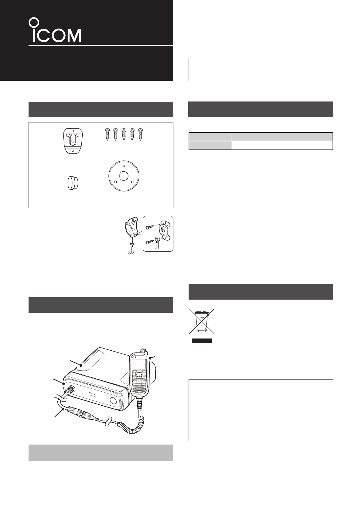
HM-218
Transceiver’s
main unit
Separation cable
(Purchase separately)
Separation kit’s
front panel
Thank you for choosing this Icom product.
READ ALL INSTRUCTIONS carefully and completely
before using this product.
Microphone hanger*1
Self-tapping screws
Connector cap*2Mounting base
*1Connect the microphone
hanger to the vehicle’s ground
using the self-tapping screws
for microphone ON/OFF hook
functions.
WORD DEFINITION
CAUTION Equipment damage may occur.
DExplicit denitions
*2
Put the connector cap on the separation cable’s connector
when the microphone is not connected.


