B&G electronics DUAL-VOX LTC-07 User manual

Models:
LTC- 07
LTC-07L
PLEASE READ BEFORE USING THE EQUIPMENT
EN 1.1
INSTALLATION AND OPERATION MANUAL
English
2
LTC
LTC 2
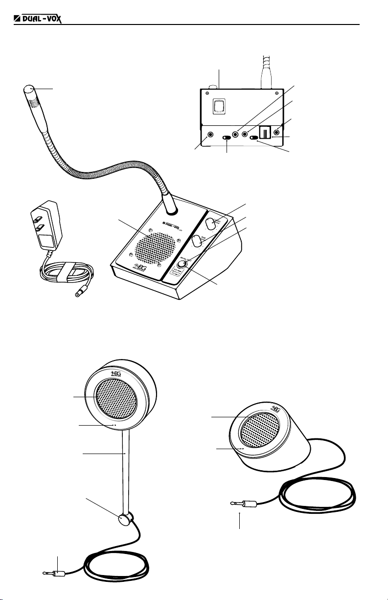
COMPONENTS
Coupling
Connector
(to electronic unit)
External speaker
External microphone
Cable conduit
Internal volume
External volume
Internal speaker
Internal microphone
with flexible neck
Push button
· MUTE (in auto mode)
· PTT (in manual mode)
LED indicator
· On
· Muted
· Manual mode
Power adapter
12V DC
External speaker
Model LTC-07
Internal Unit
External speaker
Model LTC-07L
Connector
(to electronic unit)
External
microphone
External
speaker
Switch
ON/ OFF / Siren
Mode selector
· Manual (PTT)
· Auto (half-duplex)
Input selector
· Headset
· Speaker
Connection for
customer service
recording (DAR)
Output (external unit
connector)
Power adapter
RJ 9 Headset
input
3.5 mm Headset
input
ON
OFF
SIREN

3
LTC
LTC 3
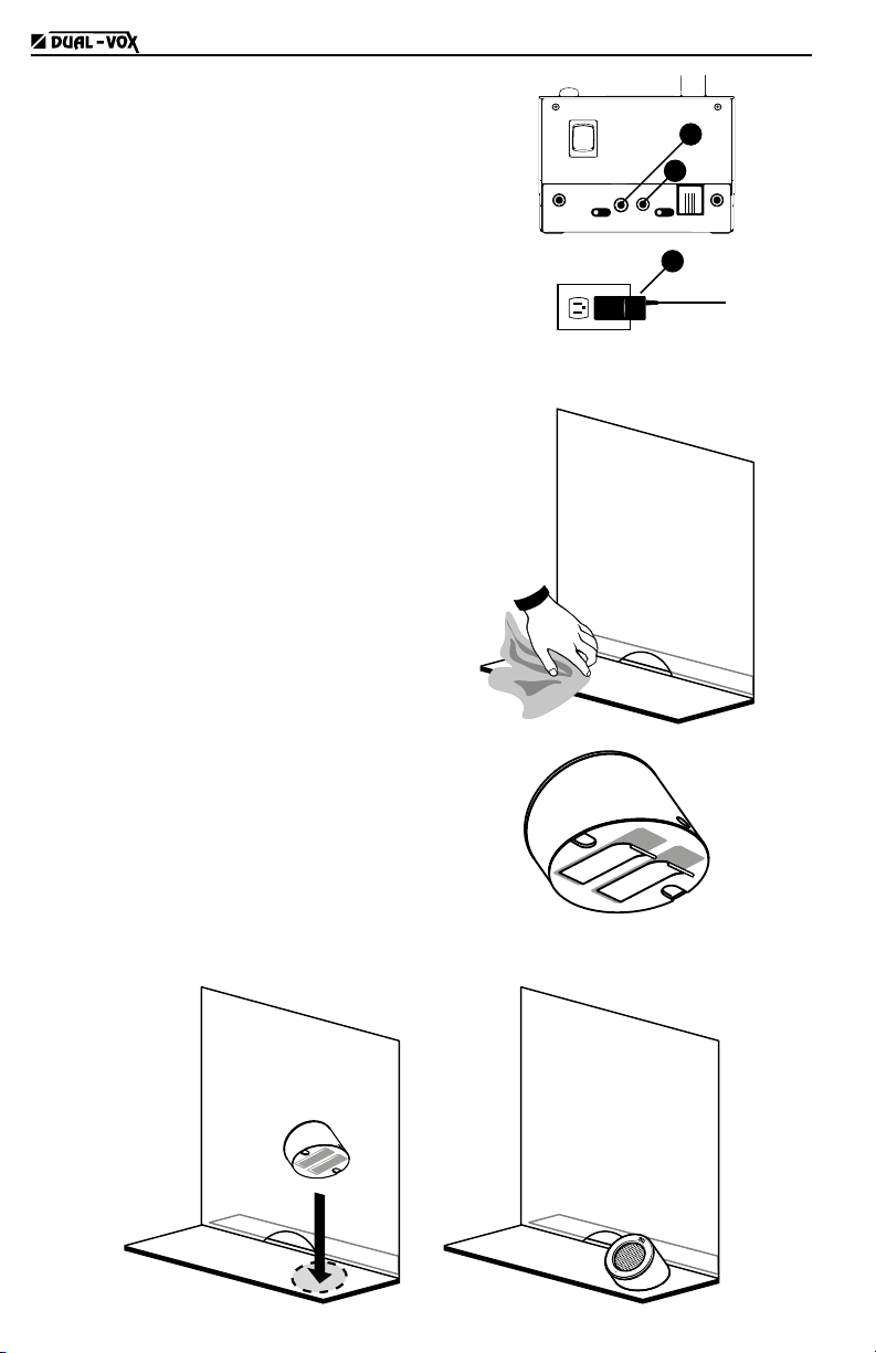
INSTALLATION LTC-07
(If your equipment model is LTC-07L, go to the next page)
Mounting the external speaker on glass
1. Clean the surface where the speaker is to be mounted
with alcohol to ensure a good adhesion.
2. Stick the mounting tapes to the back of
the speaker and remove the protective
layer from the tapes.
3. Secure the speaker to the glass by
pressing hard.
4. Pull the cable carefully to maximize its
length and to ensure a good presentation
of the installation without cable slack.
5. Introduce the upper end of the tube to the
speaker and the lower end to the coupling.
2
3
5
5
4
6. Apply glue to the surface of the coupling and stick to the glass.
Glass
7. Place the round sticker on the inner side of the glass, so
that the sticker covers the mounting tapes.
4
LTC
LTC 4
8. Pass the cable from the external speaker
to the inner side of the barrier and
connect the speaker to the internal unit.
9. Connect the power adapter to the internal
unit and to the electrical outlet. The
equipment is now ready to be turned on.
ON
OFF
SIREN
8
9
9
100 - 240V AC
INSTALLATION LTC-07L
(If your equipment model is LTC-07, return to
the previous page)
1. Clean the surface where the speaker is
to be mounted with alcohol to ensure a
good adhesion.
2. Stick the mounting tapes to the bottom
of the speaker and remove the protective
layer from the tapes.
3. Secure the speaker to the desk by pressing hard.

5
LTC
LTC 5
4. Pass the cable from the external speaker
to the inner side of the barrier and
connect the speaker to the internal unit.
5. Connect the power adapter to the internal
unit and to the electrical outlet. The
equipment is now ready to be turned on.
ON
OFF
SIREN
8
9
9
100 - 240V AC
CONNECTION TO THE CUSTOMER SERVICE
RECORDING EQUIPMENT DAR-04
(complementary product)
DAR-04 (Digital Audio Recording) is a equipment that
complements the application of the DUAL-VOX.
Allows to record customer service conversations on a
continuous basis, according to the schedule defi ned
in the software.
ON
OFF
SIREN
DAR-04
OPERATION
Both units are equipped with microphone and speaker
to provide 2-way half-duplex communication (2-way
communication with one way at a time).
The recommended speaking distance to the internal
microphone is 5 to 10 cm.
5 - 10 cm
Switching on the equipment
Power on/off is controlled by a 3-position
switch on the back of the internal unit.
To turn the equipment on, pull the switch up to
its upper position.
To turn off the equipment, pull down the
switch to its central position.
LTC-06
ON
OFF
SIREN
ON
OFF
SIREN
Intercom modes
While the equipment is on, the exterior interior
channel is permanently open, so that sounds from
outside are always heard on the internal side.
To control the opening of the interior exterior
channel, the equipment has two operation modes:
automatic mode and manual mode.
The mode is changed from the sliding switch
located at the backside. Slide the switch to the
left position for automatic mode, and to the right
position for manual PTT mode.
ON
OFF
SIREN
MODE
SELECTOR
MODE
SELECTOR
OFF
SIREN
AUTOMATIC MANUAL PTT
This manual suits for next models
1
Table of contents
Languages:
Other B&G electronics Microphone manuals


