B&K 1606 User guide

Vibration Pick-up Preamplifier Type
1606
To
be
used
in
combination
with
the
B & K
accelerometers
and
indicating
instruments.
Meas-
urement
of
acceleration,
velocity
and
displace-
ment.
Built-in
shaker
table
for
calibration
of
complete
measuri11g
arrangement.
Ncerum,
Denmark
.
~
80
05 00
.
~
BRUKJA,
Copenhagen
. Telex:
5316
EIB
160!)


Vibration Pick-up Preamplifier
Type 1606
Reprint
March
1967

Contents.
Description
. . . . . . . . . . . . . . . . . . . . . . . . . . . . . . . . . . . . . . . . . . . . 3
General
. . . . . . . . . . . . . . . . . . . . . . . . . . . . . . . . . . . . . . . . . . . . . . . . . . . . . . . . . . . . . 3
Amplifier
. . . . . . . . . . . . . . . . . . . . . . . . . . . . . . . . . . . . . . . . . . . . . . . . . . . . . . . . . . . . 4
Amplification
. . . . . . . . . . . . . . . . . . . . . . . . . . . . . . . . . . . . . . . . . . . . . . . . . . . . 4
Distortion
. . . . . . . . . . . . . . . . . . . . . . . . . . . . . . . . . . . . . . . . . . . . . . . . . . . . . . . 5
Lower
Limiting
Frequency
. . . . . . . . . . . . . . . . . . . . . . . . . . . . . . . . . . . . . . 6
Integrating
Networks
. . . . . . . . . . . . . . . . . . . . . . . . . . . . . . . . . . . . . . . . . . . . . . . . 6
Frequency
and
Dynamic
Ranges
. . . . . . . . . . . . . . . . . . . . . . . . . . . . . . . . . . 8
Built-in
Shaker
Table
. . . . . . . . . . . . . . . . . . . . . . . . . . . . . . . . . . . . . . . . . . . . . . . . 9
Operation
.............................................
10
Measuring
Arrangement
..............................................
10
CaHbration
of
Measuring
System
. . . . . . . . . . . . . . . . . . . . . . . . . . . . . . . . . . . . . . 12
Adjustment
to
the
Vibration
Signal
. . . . . . . . . . . . . . . . . . . . . . . . . . . . . . . . . . . . 14
l\feasurement
. . . . . . . . . . . . . . . . . . . . . . . . . . . . . . . . . . . . . . . . . . . . . . . . . . . . . . . . 14
Acceleration
. . . . . . . . . . . . . . . . . . . . . . . . . . . . . . . . . . . . . . . . . . . . . . . . . . . . .
14
Velocity
.........................................................
15
Displacement
. . . . . . . . . . . . . . . . . . . . . . . . . . . . . . . . . . . . . . . . . . . . . . . . . . . .
15
Specifications
..........................................
17

Description.
General.
The
Vibration
Pick-up
Preamplifier
Type
1606 is
designed
for
use
in
vibra-
tion
measuring
systems
and
constitutes
an
important
link
between
the
B & K
Accelerometers
and
the
appropriate
measuring
amplifier,
e.g.
Frequency
Analyzer
Type
2107, Audio
Frequency
Spectrometer
Type
2112
or
Microphone
Amplifier
Type
2603.
Input
Capacitive
Attenuator
~
Sensitivity
Adjustment
Shaker
Table
+
Amplifier
>
Amplitude
Adjustment
Integrating
Networks
~
AC
mains
100-2J.OV
To
Type
2107,2112,
--.2603
or
2801
261186
Fig.
1.
Block
diagram
of
Preamplifier
with
built-in
shaker
table.
The
Preamplifier
mainly
consists
of
a
two-stage
amplifier,
a set
of
integrat-
ing
networks
and
a
built-in
shaker
table
for
calibration
purposes.
The
input
impedance
of
the
amplifier
is
made
high
to
ensure
a
low
cut-off
frequency
of
the
accelerometer.
For
example
when
the
B & K
Accelerometers
are
employed,
measurements
can
be
made
down
to
2 Hz (c/s).
By
selecting
various
built-in
integrating
networks,
the
acceleration
dependent
signal
derived
from
the
Accelerometer
can
readily
be
converted
into
a
signal
which
is
propor-
tional
to
the
velocity
or
displacement
of
the
object
under
investigation.
The
built-in
shaker
table
allows
the
complete
measuring
set-up
to
be
calibrated
at
an
acceleration
level
of
1 G
*).
Both
filament
'
and
plate
voltages
for
the
•)
G
equals
the
acceleration
obtained
by
the
gravitational
force of
attraction
of
the
eartll
3

two-stage
amplifier
are
supplied
via
a
7-cored
cable
from
the
Analyzer
or
Amplifier
employed
as
the
indicating
instrument.
Amplifier.
A
variable
capacitive
attenuator
in
the
input
circuit
makes
if
possible
to
attenuate
the
input
signal
by
40
or
80 dB,
before
it
is
applied
to
the
two-
stage
amplifying
circuit.
This
circuit
contains
a
double
triode
which
has
a
continuously
variable
sensitivity
control
in
the
feedback
circuit.
The
input
resistance
measured
from
the
terminal
"Input"
is
independent
of
the
sensitivity
setting,
and
is
as
high
as
200
M.Q.
Amplification. By
means
of
the
continuously
variable
sensitivity
control
the
amount
of
amplification
can
be
regulated.
However,
at
the
same
time
the
amount
of
negative
feedback
is
also
changed,
therefore
influencing
the
fre-
quency
characteristic
to
a
certain
extent.
When
the
"Sensitivity
Adjustment"
is
in
position
"0"
the
negative
feedback
will
reach
its
highest
value,
while
the
lowest
value
is
obtained
when
the
Preamplifier
is
adjusted
for
maximum
amplification,
position
"10".
The
influence
on
the
frequency
characteristic
can
be
seen
in
Fig. 2
where
the
response
is
reproduced
for
three
different
-
db
I
Odb
./'l~
ype
1606
/1
·2'
//
~
'
~
y
,,___
v/
I I
'/
~
.:
•38~
I
/'Odb
/•38di
20
0.1 0.2 0.5
--.Frequency
-- -
~
;;:--
~
ccelerometor
(400 pF)
• Type
1606
5
10
20
(a)
db
15
I I I
0; 3;10;30cnd llO m
Extension Coble
~
10
20
50
100
200
(b) KC/s
Ulf81
Fig. 2.
Typical
frequency
response
of
Preamplifier
when
set
to
"Acceleration".
"0
dB"
, "+ 20
dB
",
"+ 30
dB"
and
"+ 38
dB"
marked
on
the
curves,
refer
to
the
amplification
set
by
"Sensitivity
Adjustment".
The
three
curves
drawn
in
full
indicated
by
"Type
1606" are valid for
the
Preamplifier
as a separate
instrument.
(a)
The
two
dotted
curves
show
the
response
of
combination
Accelerometer
with
capacity
400
pF
and
Preamplifier.
By
combination
of
Accelerometer
with
capacity
1ooo
pF
and
Preamplifier
the
cut-off
frequency
corresponds
to a
lower
frequency.
(b)
The
three
full-line
curves
are
valid
for
the
Preamplifier
when
no
Exten-
sion
Cable
has
been
used
between
Preamplifier
and
indicator.
When
Extension
Cables are used,
dotted
curves
are valid.
The
curve
indicated
by
"0 to +
20
dB
" is also valid for lengths
of
Extension
Cables
up
to
100m.
4

values
of
gain,
viz. 0, 20
and
38 dB.
The
maximum
amplification
which
can
be
achieved
is
approximately
38
db
and
is
obtained
with
the
capacitive
"Attenuator"
in
position
"1",
the
"Sensitivity
Adjustment"
in
position
"10"
and
the
integration
switch
in
position
"Acceleration".
Distortion.
The
maximum
output
voltage
which
can
be
supplied
from
the
two-stage
amplifier,
i.e.
from
the
output
of
the
Preamplifier
when
set
for
"Acceleration",
is
also
dependent
on
the
amount
of
negative
feedback.
This
can
be
seen
from
Fig. 3,
where
a
typical
nonlinear
distortion
versus
the
output
peak
voltage
of
the
Preamplifier
when
in
position
"Acceleration"
is
0
~2
z
r
0
-
------
-
~
I
- - - Maximum I
amplification
I
(+3Bdb)
r-
-
--
Minimum
amplification/
I
(Odb)
I I
I I
- - I /
- - k
~
......-::::::
~v
____..
5
10
15
20
25
30
35
-
-.
__..Voltage
on
output
of
Preamplifier
(pas.
..
Acceleration
'')
Voltpeak
.2&1188
Fig.
3.
Typical
nonlinear
distortion
of
the
Preamplifier
at
mmzmum
and
maximum
amplification
.
The
curves
are valid for
the
frequencies 20 Hz (c/s)-
20
kHz
(kc/s)
and
without
Extension
Cable
between
Preamplifier
and
indicator
instrument.
illustrated.
In
order
to
avoid
distortion
higher
than
approximately
1 %
at
minimum
amplification
(0 dB)
and
higher
than
approximately
3 ,%
at
maximum,
this
output
voltage
should
not
exceed
10
Volts
peak
and
approx-
imately
20 Volts
peak
respectively.
Refer
also
Fig
. 4,
where
the
Preamplifier's
maximum
oulput
voltage
vs.
frequency
is
given
when
used
in
the
"Accelera-
tion"
condition
.
When
employing
extension
cables
between
the
output
of
the
Preamplifier
and
the
following
Microphone
Ampl!fier,
Spectrometer
or
Analyzer
the
capacity
of
these
cables
loads
the
amplifier
in
tl)e
Preamplifier.
Thus
the
maximum
output
voltage
has
to
be
lowered
as
indicated
by
the
dotted
lines
(3
m,
10 m, 30
m,
and
100 m)
in
Fig.
4.
5

Ypoak
20
--
-_-,-,
-.......,_
l.
ExJnslon
' ,
'',
"\
C.bl~
-
'\''
~
15
t-
-+---+--+--+--+-~
,,
t-
'-'.,'
r--:
''--:--
-t-
-"\
<+---1
',
\~,m
\ 10rrt\ ' ,
10
t-
-+---+--t-
-+--.:...1----.
JO~
c-,
!---"''
~
-1----1
Distortion J•k opprox. 100,;;, '
Maximum omplif.ication. 'T
',,
0~-+---+--+--+---+--~~---+-~~~
0.1 0.2 0.5
10
20
50
100
200
(a)
KC/s
0.5
Distortion
1•k
opprox.
Minimum amplification
(b)
20
No
Extensi
on
LCoblo
50
100
200
KC/s
261169
Fig.
4.
Maximum
peak
voltage
from
output
of
Preamplifier
when
set to
"Acceleration".
Full-line
curves are
valid
when
no
Extension
Cable is
used
between
Preamplifier
and
indicator.
Dott
ed lines valid for various
lengths
of
Extension
Cable.
(a)
For
"Sensitivity
Adju$tment"
in
position
"10"
(maximum
amplification
of
amplifier
stage)
the
:nonlinear
distortion
from
the
Preamplifier
will
be ·in
the
order
of
3 %
when
output
voltage is as l1igh as
given
by
the
curves.
(b)
For
"Sensitivity
Adjustment"
in
position
"0"
(minimum
amplification
of
amplifier
stage)
the
nonlinear
distortion
will
be
in
the
order
of
1 %
when
output
voltage is as
high
as
given
by
the
curves.
Lower
Limiting
Frequency.
The
output
impedance
of
the
Accelerometers,
intended
for
use
with
the
Preamplifier,
can
be
approximately
equalized
by
a
capacitor
which
is
in
series
with
the
signal
source.
Due
to
this
capacity
the
input
resistance
of
the
Preamplifier
determines
the
lower
limiting
frequency
of
the
combination
Accelerometer
plus
Preamplifier.
In
Fig.
2
the
frequency
responses
at
the
lower
frequencies
are
shown.
The
curves
are
valid
for
Accelerometer
Sets
having
400
pF
internal
capacitance,
with
the
Preamplifier
set
respectively
for
minimum
and
maximum
amplification.
Integrating
Networks.
The
output
from
the
amplifier
circuit
can
be
fed
to
the
integrating
networks.
Employing
the
different
networks
vibration
measurements
can
be
carried
out
also
'
as
a
measurement
of
velocity
or
displacement,
by
using
one
of
the
B & K
Accelerometers
in
combination
with
the
Preamplifier.
When
the
Pre-
amplifier
is
switched
for
velocity
measurements,
the
output
from
the
Accelerometer
is
integrated
once
with
respect
to
time.
With
the
integration
switch
of
the
Preamplifier
set
to
position
"Displacement"
a
further
integra-
tion
with
respect
to
time
takes
place,
and
the
output
from
the
Preamplifi'er
will
now
be
proportional
to
the
displacement
of
the
vibrating
body,
at
the
point
where
the
Accelerometer
is
mounted.
··
Design.
When
periodic
vibrations
are
considered,
and
one
of
the
mechanical
quantities,
acceleration,
velocity
or
displacement
is
kept
constant,
the
magnitude
of
the
remaining
two
quantities
will
depend
upon
the
frequency
6

'
of
the
vibrations.
This
is
readily
seen
from
the
derivation
of
the
respective
quantity.
If
the
acceleration
is
given
as
a =
Ao
sin
(wt)
the
velocity
will
be:
v =
adt
=-
~Ao
cos
{wt) +c1,
w
and
the
displacement:
('
vdt
=-
Ao
sin
(wt) +c2,
J
w2
Cl
= 0
C2 = 0
Generally
speaking,
the
magnitude
of
the
electrical
quantity
measured
on
an
indicating
instrument
will
therefore
be
gr
ea
test
if
the
measurement
is
carried
out
as
a
measurement
of
acceleration.
0
db
-10
-20
-30
§
-40
~
c
:;;,
c
~
~-50
Lo
1 2 5
~Frequency
10
20
50
100
200 500
1000
2000
C/s
5000 10000
f!i8038
Fig. 5.
Amplitude
versus
frequency
characteristics
of
integrating
networks.
The
electrical
attenuation,
which
takes
place
when
velocity
or
displacement
measurements
are
carried
out
employing
an
accelerometer
in
conjunction
with
the
Preamplifier,
can
be
seen
from
the
curves
of
Fig.
5.
To
better
un
'
derstand
what
actually
happens
the
basic
diagram
of
an
integrating
net-
work
should
be
considered,
see
Fig.
6.
The
voltage
across
the
capacitor
is
given
by:
1 -
ec = C
~
idt
7

and
the
total
input
voltage
is:
1
\'
e = ex + ec = Ri +C J
idt
To
obtain
a
correct
integration
the
values
of
R
and
C
must
be
chosen
sucb
e
that
ex'>>
ec,
and
consequently
i N
R,
which,
substituted
in
the
equation
above,
gives
ec
00
R~
~edt
A
specific
combination
of
a
resistor
and
a
capacitor
can
only
be
used
in
a
limited
frequency
range,
as
for
the
high
frequencies,
the
signal
level
across
J611PD
Fig.
6.
Basic diagram
of
an integrating
network.
the
capacitor
decreases
to a
too
low
value,
the
signal-noise
ratio
will
con-
sequently
be
too
low. At
the
low
frequencies
the
requirement
en>>
ec is
no
longer
fulfilled,
which
means
that
the
integration
will
be
incorrect.
To
cover
the
desired
frequency
range
various
combinations
of
resistors
and
capacitors
are
used,
which
can
also
be
seen
from
Fig.
5.
Two
combinations
are
used
for
"Velocity",
whereas
three
are
used
for
"Displacement".
Frequency
and
Dynamic
Ranges.
As
the
networks
cannot
be
used
below
their
low-frequency
cut-off
(indicated
on
the
curves
in
Fig.
5),
the
integra-
tion
switch
is
for
the
different
positions,
where
the
networks
are
inserted,
indicated
with
the
lowest
frequency
at
which
practically
correct
integration
still
takes
place.
Application
of
the
curves
of
Fig. 5
to
a
numerical
example
might
be
illustrative:
(a)
Measurement
of
Velocity:
If
the
deflection
on
the
voltmeter
is
taken
to
be
100 %
when
the
accelera-
tion
of
a
pure
sinusoidal
vibration
with
a
frequency
of
500 Hz (c/
s)
is
measured,
the
deflection
on
the
meter
will
be
3.16
%,
when
the
switch
on
the
Preamplifier
is
set
to
position
"Velocity-
Lower
Limiting
Fre-
quency
30
Hz
(c/s)
".
In
case
the
switch
is
set
to
position
"Velocity
-
Lower
Limiting
Fre-
q~ency
3
Hz
(cis)"
the
deflection
on
the
indicating
meter
will
only
be
0.316%.
(b) Measurement
of
Displacement:
8
Setting
the
switch
to
position
"Displacement
-
Lower
Limiting
Freque:acy
300
Hz
(c/s)
",
results
in
a
meter
deflection
of
approximately
10
%,
but
'

•
•
•
this
indication
will
be
slightly
inaccurate
du
e
to
the
be
nding
of
the
curve
.
By
changing
over
to
position
"Displacement-
Lower
Limiting
Frequency
30
Hz
(c/s)
",
a
more
a
cc
urate
res
ult
is
obtained
,
but
the
defle
ction
on
the
meter
will
only
be
o.1
%.
(An
accurate
reading
can
be
obtained
by
in-
creasing
the
sensitivity
of
the
indicating
instrument).
If
the
position
"
Displacement
-Lower
Limitin
g
Fr
e
qu
e
ncy
3
Hz
(c/
s)"
is used,
the
indica-
tion
should
be
o.001 %,
but
for
mod
era
te
accel
e
ration
level
s
the
noise
and
hum
level
may
here
cause
serious
errors
in
the
measured
results
.
From
the
above
it
can
be
seen
that
vib1 a
lion
measurements
should,
also
from
a
measuring
point
of
view,
be
carried
out
as
measurements
of
acceleration
.
This
is
especially
true
at
higher
frequencies.
When
measurements
of
the
velocity
or
deflection
are
required,
care
must
be
taken
regarding
the
position
of
the
integration
switch
on
the
Preamplifier.
It
is
obvious
that
the
highest
permissible
Lower
Limiting
Frequency
position
of
the
switch
will
give
the
most
satisfactory
result.
The
time
constants,
RC,
for
the
different
networks
are
chosen
to
be
10-1,
w-2
and
10-
3,
which
can
be
seen
from
the
curves
shown
in
Fig
. 5.
Built-in Shaker Table.
A
sketch
of
the
shaker
table
is
shown
in
Fig.
7,
which
illustrates
the
ex-
tremely
simple
principle
of
operation.
The
moving
element
is
suspended
on
a
stretched
metal
strip,
and
the
vibrator
is
excited
by
a
small
electro-
magnetic
system
fed
from
the
mains
supply.
By
varying
the
tension
of
the
metal
strip
the
resonance
frequency
of
th_.
table
can
be
adjusted
to
the
frequency
of
the
power
supply
voltage.
In
this
way
almost
pure
sinusoidal
vibrations
are
obtained.
The
amplitude
of
tile
vibrations
can
be
adjusted
by
varying
the
voltage
across
the
coil
of
the
electromagnetic
exciter.
To
determine
this
level a
small
sphere
,
supported
at
three
points,
is
built
into
the
hollow
axis
of
the
shaker
table,
Fig.
7.
When
this
sphere
just
commences
to
rattle
the
peak
acceleration
of
the
table
is
1 G.
Fig.
7.
Illustration
of
mechanical
system
of
built-in
shaker
table.
9

Attenuot
ion
Sensitivity
Adjustment
Resonance
Adjustment
Operation
.
I
ntegrotion
Switc
-poled
plug
1606
Fig.
8.
Front
plate
view
of
Vibration
Pick-up
Preamplifier.
Measuting Arrangement.
The
Preamplifier
should
be
used
in
conjunction
with
one
of
the
following
indicating
instruments:
(1)
Audio
Frequency
Spectrometer
Type
2112
12)
Frequency
Analyzer
Type
2107
(3)
Microphone
Amplifier
Type
2603
(4)
Microphone
Power
Supply
Type
2801 +
Electronic
Voltmeter
Type
2409
or
similar
indicating
instrument.
Measuring
arrangements
illustrating
the
means
of
connection
to
the
various
instruments
are
shown
in
Fig. 9.
When
a
recording
of
the
measurements
is
desired,
the
above
mentioned
instruments
can
be
connected
to
the
Level
Recorder
Type
2305. A
great
advantage
which
is
gained
by
using
the
Spectro-
meter
Type
2112
or
Analyzer
2107
in
conjunction
with
the
Level
Recorder
Type
2305 is
that
an
analysis
of
the
vibrations
investigated
can
be
carried
out
automatically
on
preprinted,
frequency
calibrated
recording
paper.
There
are
two
possible
methods
of
connecting
the
instruments:
(1)
The
measuring
arrangement
is
placed
in
the
immediate
vicinity
of
the
measuring
point.
10
•
f
•

lii
•
::
..-
:::
:i : @
~
•
=
_c-:_-:E
i
'~
·
·
:;;_
··
• '-
@ =
"'
iii
"':
@
@
...
2803
~107
n
1808
~
I,U,
m,IY
•
:::-
.-
:::
~
~
~
-
~
_
-:f
i
~··
§ _ ,;•,
,,
!e!
·
2112
Fig.
9.
Complete
measuring
arrangements
for
the
measurement
of
mechanical
vibrations.
The
four
different
instruments
are
the
indicating
apparatuses
.
The
seven-pin plug
of
the
Preamplifier
me
as
urin
g
cable
should
be
connected
to
the
input
marked
"Condenser
Microphone"
on
the
front
panel
of
Type
2107, 2112
or
2603.
The
input
switch
of
the
indicating
instrument
should
likewise
be
set
to
position
"Condenser
Microphone".
Typical
frequency
characteristics
of
the
measuring
arrangements
used
under
the
above
condition
are
shown
in
Fig.
10.
(
2)
The
measuring
arrangement
is
placed
some
distance
away
from
the
measuring
point.
The
seven-cored
measuring
cable
from
the
Preamplifier
can
be
extended
by
Extension
Cables
Type
AO
0027
(length
3
m),
Type
AO
0028
(10
m)
or
Type
AO
0029 (30
m).
Several
lengths
of
Extension
Cables
can
be
coupled
together.
The
influence
upon
the
frequency
response
at
the
higher
fre-
11
db
0
20
O~b
I [ I
~
Accelerometer
(1000pF)
,~~
//
~
~~
~
Accelerometer
(400
pF)
I I
~
38d~
i
I
1 5
10
2
----.
Frequency
Jdb
tl
+20~b
-
~
+38 db
"·
'
10
4 2
C/5
5
10
5
.?61193
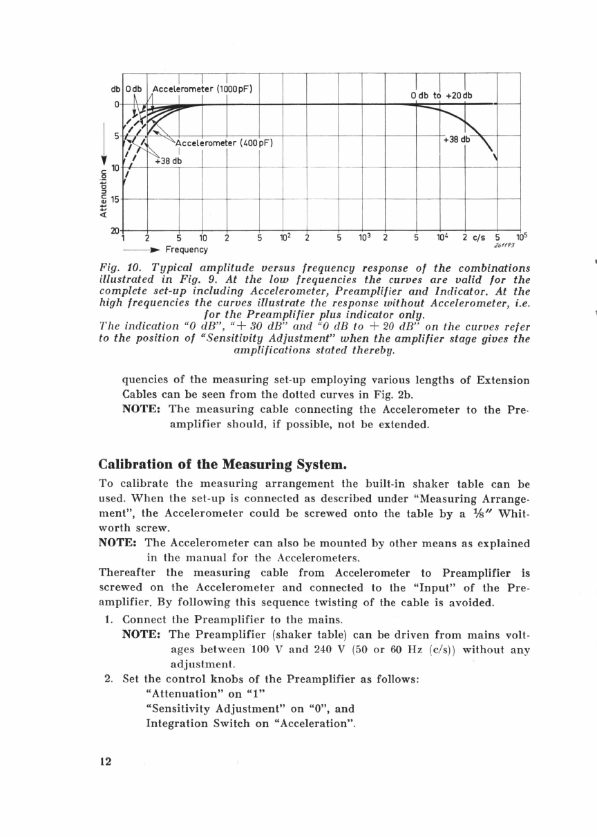
Fig.
10
.
Typical
amplitude
versus frequency response
of
the
combinations
illustrated
in
Fig. 9.
At
the
low
frequencies tl1e curves are
valid
for
the
complete
set-up
including
Accelerometer, Preamplifier
and
Indicator.
At
the
high frequencies
the
curves
illustrate the response
without
Accelerometer, i.e.
for
the
Preamplifier
plus
indicator only.
The
indication
"0
dB
",
"+
30
dB
"
and
"0
dB
to +
20
dB"
on
th
e curves
refer
to
the
position
of
"Sensitivity
Adjustment"
when
the
amplifier
stage gives
the
amplifications
stated thereby.
quencies
of
the
measuring
set-up
employing
various
lengths
of
Extension
Cables
can
be
seen
from
the
dotted
curves
in
Fig. 2b.
NOTE:
The
measuring
cable
connecting
the
Accelerometer
to
the
Pre
-
amplifier
should,
if
possible,
not
be
extended.
Calibration
of
the
Measuring System.
To
calibrate
the
measuring
arrangement
the
built-in
shaker
table
can
be
used.
When
the
set-up
is
connected
as
described
under
"Measuring
Arrange
-
ment",
the
Accelerometer
could
be
screwed
onto
the
table
by
a lfs"
Whit-
worth
screw.
NOTE:
The
Accelerometer
can
also
be
mounted
by
other
means
as
explained
in
th
e
manu
al
for
th
e
Accelerometers.
Thereafter
the
measuring
cable
from
Accelerometer
to
Preamplifier
is
screwed
on
the
Accelerometer
and
connected
to
the
"Input"
of
the
Pre-
amplifier.
By
following
this
sequence
twisting
of
the
cable
is
avoided.
1.
Connect
the
Preamplifier
to
the
mains.
NOTE:
The
Preamplifier
(shaker
table)
can
be
driven
from
mains
volt-
ages
between
100
V
and
240 V
(5
0
or
60Hz
(c/s))
without
any
adjustment.
2.
Set
the
control
knobs
of
the
Preamplifier
as
follows:
12
"Attenuation"
on
"1"
"Sensitivity
Adjustment"
on
"0",
and
Integration
Switch
on
"Acceleration"
.

3.
The
Microphone
Amplifier,
Spectromet
er
or
Analyzer
should
be
set
to:
"
Function
Selector"
on
"
Linear
"
"Meter
Switch"
on
"Peak"
"Fast"
"Meter
Range"
and
"Range
Multiplier"
for
a
sensitivity
of
100 mV.
4.
By
turning
the
"Amplitude
Adjustment"
of
the
Preamplifier
a
small
deflection
of
the
indicating
instrument
should
be
obtained.
If
necessary,
the
"Sensitivity
Adjustment"
can
be
adjusted
to
a
higher
value
than
set
to
in
item
2).
5.
A
maximum
deflection
of
the
indicating
meter
pointer
(resonance
of
shaker
table
suspension)
should
be
achieved
by
turning
the
knob
"Resonance
Adjustment"
of
the
Preamplifier.
During
the
resonance
adjustment
the
"Amplitude
Adjustment"
may
be
readjusted.
6.
Adjust
the
amplitude
of
the
shaker
table
by
"Amplitude
Adjustment"
so
that
the
built-in
sphere
is
brought
to
the
beginning
of
rattling.
At
the
point
where
the
rattling
commences,
the
peak
acceleration
on
the
shaker
table
is
equal
to the
acceler
a
tion
from
th
e g
ravitation
for
ce
of
the
earth.
NOTE:
If
the
sphere
cannot
be
made
to
rattle,
even
by
turning
"Amplitude
Adjustment"
to
maximum,
the
Preamplifier
should
be
placed
on
a
soft
rubber
pad
or
similar
type
of
material.
In
this
manner
the
vibration
amplitude
of
the
shaker
table
will
be
increased.
The
vibration
of
the
shaker
table
is,
to
some
degree,
affected
by
the
touching
of
the
Preamplifier's
control
knobs,
therefore
,
when
checking
the
rattling
point,
the
Preamplifier
should
be
released
.
The
condition
where
the
rattling
starts
is
readily
found
aurally.
For
a
more
accurat
e dete
rmination
a he
adphone
or
an
osc
illos
cop
e
can
be
connected
to
the
output
"Recorder"
of
the
associated
measuring
instrument.
The
rattling
of
the
sphere
sets
in
where
the
pure
sine-wave
signal
derived
from
the
shaker
table
vibration
is
distorted
.
a.
Accelerometer
with
a
Sensitivity
Higher
than
15 mV/G.
The
sensitivity
of
the
indicating
apparatus
should
.
be
set
to
"1
V",
and
the
the
deflection
of
its
indicating
meter
should
be
adjusted
to o.98 V
by
"Sensitivity
Adjustment"
of
the
Preamplifier
.
During
the
following
measurements
full
deflection
(1
V)
then
equals
looo
cm/sec2.
NOTE:
An
unstable
meter
deflection
may
be
avoided
by
placing
the
Pre
-
amplifier
on
a
soft
rubber
pad
or
similar
.
b.
Accelerometer
with
a
Sensitivity
Lower
than
15· mV/G.
The
sensitivity
of
the
indicating
apparatus
should
be
set
to
"100
mV"
and
the
deflection
of
its
indicating
meter
should
be
adjusted
to 98
mV
by
the
"Sensitivity
Adjustment"
of
the
Preamplifier.
During
the
following
measurements
full
deflection
(o.l
V)
then
equals
looo
cm/sec2.
13

After
calibration
the
Accelerometer
is
unscrewed
from
the
shaker
table,
and
the
power
supply
is
disconnected
from
the
Preamplifier.
NOTE:
Protect
the
connection
cable
between
Accelerometer
and
indicating
apparatus
by
removing
the
cable
from
the
Accelerometer
before
this
is
dismounted.
During
the
following
adjustment
and
measurement
the
position
of
the
"Sensitivity
Adjustment"
should
not
be
altered,
otherwise
the
calibration
will
be
lost.
Adjustment
to
the
Vibration
Signal.
1.
Mount
the
Accelerometer
on
the
object
to
be
investigated.
2.
Connect
Accelerometer
to
"Input"
of
Preamplifier.
3.
Set
indicating
apparatus
in
position
"Linear"
and
check
that
the
indicat-
ing
meter
does
not
show
a
higher
voltage
than
indicated
in
Fig.
4.
If
necessary,
the
voltage
can
be
brought
below
the
stated
peak
voltages
by
attenuating
the
input
voltage
to
the
Preamplifier
with
control
knob
"Attenuation".
4.
Select
RMS,
Average
or
Peak
{half
peak-to-peak)
type
of
detection
by
the
"Meter
Switch"
on
the
indicating
apparatus.
If
the
B & K
Level
Recorder
Type
2305
is
used
for
recording
the
results,
the
appropriate
type
of
detection
is
selected
by
the
"Rectifier
Response"
switch
on
this
apparatus.
l\leasurement.
I. ACCELERATION
14
Keep
Integration
Switch
on
"Acceleration".
1.
Accelerometer
with
Sensitivity
Higher
than
15 mV/G.
The
value
of
the
acceleration
in
cm/sec.2
is
then
achieved
as
follows:
Read
value
in
Volts
X 103 X
the
value
indicated
by
switch
"Attenu
ation"
of
the
Preamplifier.
Example:
Meter
reading:
o.4 V
Position of
"Attenuation":
"102"
The
acceleration
will
then
be: o.4 X 10' X
102
= 40ooo cm/sec2
2.
Accelerometer
with
Sensitivity
Lower
than
15
mV/G.
Read
value
in
Volts
X 103 X 10 X
the
value
indicated
by
switch
"Attenuation"
of
the
Preamplifier
.
Example:
Read
value
and
position
of '
Attenuation"
are
as in
example
above.
The
acceleration
will
in
this
case be: o.4 X 10' X
10
X
102
= 400ooo cm/sec2•

II. VELOCITY
The
Integration
Switch
should
be
set
to
"Velocity".
The
two
positions
should
be
used
as
stated
below.
a. "
Velocity-
Lower
Limiting
Frequency
3
Hz
(c/s)"
when
the
fre-
quencies
covered
by
the
vibration
signal
are
within
the
range
3
to
30
Hz
(cis)
or
higher.
b. "
Velocity-
Lower
Limiting
Frequency
30
Hz
(c/s)"
when
the
fre
-
quencies
covered
by
the
vibration
signal
are
higher
than
30
Hz
(cis).
1.
Accelerometer
with
Sensitivity
Higher
than
15
mV/G.
The
value
of
the
velocity
in
em/sec.
is
derived
as:
The
read
value
in
Volts X
the
value
(10
or
102 em/sec.)
indicated
by
the
position
of
Integration
Switch
X
the
value
indicated
by
switch
"Attenuation"
on
Preamplifier
.
Example:
Read value: o.04 V
Integration
Switch: "10 em/sec" ("30
ds")
"Atten~ation":
"1"
The
velocity
is
then: o.04 X
10
X 1 = o.4 em/sec.
2.
Accelerometer
with
Sensitivity
Lower
than
15 mV/G.
The
read
value
in
Volts X
the
value
(10
or
102 em/sec.)
indicated
by
the
position
of
the
Integration
Switch
X 10 X
the
value
indicated
by
switch
"Attenuation"
on
Preamplifier
.
Example:
Setting
and
read
value as above in
item
1
).
The
velocity will in
this
case be: o.04 X
10
X
10
X 1 = 4 em/sec.
III.
DISPLACEMENT
The
Integration
Switch
should
be
set
to
position
"Displacement".
The
three
possible
positions
should
be
us~d
when:
a.
"Displacement-
Lower
Limiting
Frequency
3
Hz
(cis)"
when
the
frequencies
covered
by
the
vibration
signal
are
in
the
range
3 to
30 Hz (c/s)
or
higher.
b.
"Displacement-
Lower
Limiting
Frequency
30
Hz
(c
i
s)"
when
the
frequencies
covered
by
the
vibration
signal
are
in
the
range
30
to
300
Hz (c/s)
or
higher.
c.
"Displacement-
Lower
Limiting
Frequency
300Hz
(cis)"
when
the
frequencies
covered
by
the
vibration
signal
are
higher
than
300
Hz
(cis).
1.
Accelerometer
with
Sensitivity
Higher
than
15 mV/G.
Similar
to
the
measurements
previously
described
the
displacement
in
em
is
derived
from:
15

The
read
value
in
Volts
X
the
value
(tO,
to-t
or
to-a
em)
indicated
by
Integration
Switch
X
the
value
indicated
by
the
switch
"Attenuation"
of
the
Preamplifier.
Example:
Read
value:
o.t
Volt
[ntcgration
Switch
on
"to-
8
em"
"Attenuation"
on
"t"
The
amplitude
will
then
be:
o.l
X
to-
1 X 1 = to-• em.
2.
Accelerometer
with
Sensitivity
Lower
than
15
mV/G.
The
amplitude
in
em
of
the
vibration
signal
is
derived
as
stated
in
item
1.
above
except
for
the
fact
that
the
result
should
be
multiplied
by
tO.
Example:
The
settings
and
read
value
are
the
same
as
in
example
1).
The
amplitude
will
now
be:
o.l
X
t0-
1 X 1 X
10
=
to-
1 em.
For
further
details
concerning
the
operation
of
the
indicating
apparatus,
refer
the
instruction
books
fo.r
the
Analyzer
Type
2t07,
the
Spectrometer
Type
2tt2
or
the
Microphone
Amplifier
Type
2603,
as
the
case
may
be.
In
addition,
reference
should
be
made
to
the
instruction
books
for
the
Accelero
-
meters
.
16

Frequency
Range:
Amplification:
Input
Impedance:
Input
Attenuator:
Specification.
o.2
Hz
(c
/
s)
to
lOOooo
Hz
(c/
s)
within
± o.5 dB
when
"Sensitivity
Adjustment"
is
set
to
"0"
(min.
amplification).
2 Hz
(c
/
s)
to
20ooo
Hz
(c
/
s)
within
± 3 dB
when
"Sensitivity
Adjustment"
is
set
to
"10"
(
max.
amplification).
Maximum
38
dB
approx.
voltage
amplification
when
set
for
acceleration
measurements.
200
M.Q
paralleled
by
approx.
50
pF.
"A
ttenuation":
Two
steps
of
40 dB
with
an
accuracy
of
± o.5 dB
re.
position
"1
".
Max.
Output
Voltage:
In
condition
"Acceleration":
20
V
peak
when
"Sensitivity
Adjustment"
is
in
posi-
tion
"10"
(max.
amplification).
10 V
peak
when
"Sensitivity
Adjustment
is
in
posi-
tion
"0"
(min.
amplification).
Hum
and
Noise
Level:
12
t-tV
approx.
referred
to
"Input"
at
maximum
amplification
and
with
Preamplifier
shaker
table
disconnected
from
the
mains.
lntegration
Switch:
Allows
selection
of
acceleration,
velocity
or
dis-
placement
measurements
of
the
investigated
vibra-
tion.
Built-in
Shaker
Table:
Driven
by
the
mains
voltage
and
brought
in
re-
sonance
with
the
mains
frequency
by
adjustment
of
the
knob
"Resonance
Adjustment".
The
accelera-
tion
of
the
shaker
table
can
be
adjusted
by
another
knob,
"Amplitude
Adjustment".
Power
Supply:
100
to
240
Volts
without
adjustment,
50
or
60
Hz
(c/s).
17

Measuring
Ranges:
Accelerometer
Type
Acceleration
Velocity
Displacement
Depending
on
the
sensitivity
and
frequency
re-
sponse
of
the
Accelerometer
employed.
Typical
measuring
ranges
of
the
complete
arrangement
consisting
of
Accelerometer,
Preamplifier
and
in-
dicating
apparatus
(Microphone
Amplifier,
Spectro-
meter
or
Analyzer).
Miqimum
Level*)
Limiting
Frequency
R.M.S.
value
Lower
Higher
I 4332 I
4332 4333 4333 4332 4333
4334 I 4335 4334 I 4334 4335
I 4335
-
-----
cm/sec2 Hz kHz
---
-1
1 I 3 2
em/sec Hz
12
18
---
0.03 ., o.1 3
o.Oo3+
o.o1+
30
ft
Hz I kHz
---
---
20 I
60
3 1
o.2+ 0.6+ 30 I 3
o.Qo3+
o.o1+ 300 I
10
1
~
= 10-•
meters
=
40
X
t0-
8 inches.
Maximum
Level:
4332-4334:
4333-4335:
Accessories
Included:
3ooo
g (peak) = 3 X
106
cm
/sec.:l (peak)
7500 g (peak) = 7.5 X
106
cm/sec
.2
(peak
)
~ower
cord,
·
screened
plug
(JP
0018),
1
Allen
key,
3
Allen
screws,
W
1h
". 'f
a>
t)'l)
f.
I
1
adaptor
W
1/8"
to
10-32
NF.
">
8 0
-;ll
*)
The
minimum
level is
limited
by
the
Preamplifier
's
internal
noise,
which
will
normally
be
at
least
6 dB
lower
than
the
corresponding
levels
in
the
table
.
+
With
main
amplifier
lower
limiting
frequency
20
Hz.
18
Table of contents
Other B&K Amplifier manuals


Popular Amplifier manuals by other brands

Hifonics
Hifonics ZEUS ZXR1200/5 user manual

American Acoustic Development
American Acoustic Development THE CUB CUB AG-100 owner's manual

Classe Audio
Classe Audio CA-5200 owner's manual

Fender
Fender Princeton Recording Amp Service manual

Yamaha
Yamaha Electone C-40 owner's manual

C.F. Martin & Co
C.F. Martin & Co Fishman Classic 4 user guide


