B&K 2627 User guide

1 Inch Preamplifier for
Condenser Microphones
Type 2627
A field
effect
transistor Preamplifier
with insert voltage calibration
capability
for
1 inch condenser
microphones. The extremely high
input impedance ensures a flat
frequency response over a wide
range. The Preamplifier conforms
with the IEC Recommendation R
327,
and the American Standard
ASA 81.10-1966.


MICROPHONE PREAMPLIFl
ER
TYPE 2627
September 1971


CONTENTS
1.
INTRODUCTION
. . . . . . . . . . . . . . . . . . . . . . . . . . . . . . . . . . . . . 5
1.
1.
GeneraI . . . . . . . . . . . . . . . . . . . . . . . . . . . . . . . . . . . . 5
1.2. Preamplifier Requirements . . . . . . . . . . . . . . . . . . . . . 5
2.
DESCRIPTION . . . . . . . . . . . . . . . . . . . . . . . . . . . . . . . . . . . . . . . 8
2.
1.
General . . . . . . . . . . . . . . . . . . . . . . . . . . . . . . . . . . . . 8
2.2. Characteristics
................
;
...........
~
.
11
Input
Characteristics . . . . . . . . . . . . . . . . . . . . . . . . . .
11
Output
Characteristics
........................
12
Frequency
Response
..........................
13
Attenuation
. . . . . . . . . . . . . . . . . . . . . . . . . . . . . . . . 14
Distortion
..................................
14
Noise
..................
.
..................
14
2.3. Environmental Sensitivity
......................
15
Temperature
................................
15
Hu!Jlidity
..................................
15
Vibration
..................................
15
Acoustic Sensitivity . . . . . . . . . . . . . . . . . . . . . . . . . . 16
Magnetic Field . . . . . . . . . . . . . . . . . . . . . . . . . . . . . . 16
Shock Sensitivity . . . . . . . . . . . . . . . . . . . . . . . . . . . . 16
3. INSERT
VOLTAGE
CALIBRATION
......................
17
3.
1.
General . . . . . . . . . . . . . . . . . . . . . . . . . . . . . . . . . . . . 17
3.2. Principle
of
The Insert Voltage Method
...........
17
Use
with
8 & K equipment
with
Insert Voltage
Calibration
Facility
...........................
18
Insert Voltage Junction Box ZH 0007
............
21
3.3. System Calibration
...........................
23

4.
USE
WITH OTHER EQUIPMENT
........................
24
4.1. Microphones
................................
24
4.2. Accelerometers . . . . . . . . . . . . . . . . . . . . . . . . . . . . . . 25
4.3. Microphone Power Supplies
....................
25
4.4. Extension Cables
............................
26
5.
SPECIFICATIONS
....................................
27
5.1. 2627 Preamplifier
............................
27
5.2. Junction Box ZH 0007
........................
28

1.
INTRODUCTION
1.1.
GENERAL
The
Type
2627 Preamplifier
is
especially designed
for
use
with
the 1 inch
B & K Condenser Microphone Cartridges
Type
4144, 4145,
and
4146.
It
features the capability
for
calibration using the insert voltage method. The
Preamplifier may also
be
used
when impedance matching
from
high
to
low
impedance
is
required. The Preamplifier may
be
powered
directly
from
the
B & K Measuring
Amplifiers
and Analyzers,
or
from
the B & K Microphone
Power Supplies.
The
input
configuration
of
the Preamplifier
is
in accordance
with
IEC
Recommendation R-237.
1.2.
PREAMPLIFIER
REQUIREMENTS
Transducers
such
as
condenser microphones generally
have
a small
capacitance associated
with
them. Therefore any preamplifier
for
use
with
these transducers must
be
of
special design.
Two
equivalent
circuit
diagrams
of
a transducer and preampIifier
are
shown in Fig.1.1.
The
transducer may
be
regarded
as
a constant current generator providing a current
jwCr
V
0.
R R
Fig.1.1. Equivalent circuits
of
a transducer
and
preamplifier
input
circuit
The constant current
circuit
may
be
simplified
further
to
the
circuit
shown in Fig.1.2.
5
c
.,....7....-'£69
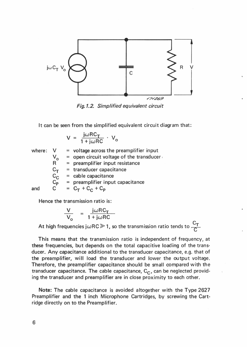
Fig.1.2. Simplifiedequivalent circuit
It can
be
seen
from
the
simplified equivalent circuit diagram
that:
v
jwRCI
. V
1 +
jwRC
0
where: V voltage across
the
preamplifier input
open
circuit voltage
of
the
transducer
,
preamplifier
input
resistance
transducer
capacitance
vo
R
Cr
Cc
Cp
cable capacitance
and C preamplifier
input
capacitance
Cr
+
Cc
+ Cp
Hence
the
transmission ratio is:
V
jwRCr
V0
1+jwRC
At
high frequencies
jwRC
~
1, so
the
transmission ratio
tends
to~
This
means
that
the
transmission ratio
is
independent
of
frequency,
at
these frequencies,
but
depends
on
the
total
capacitive loading
of
the
trans-
ducer.
Any
capacitance additional
to
the
transducer
capacitance, e.g.
that
of
the
preamplifier, will load
the
transducer
and lower
the
output
voltage.
Therefore,
the
preamplifier capacitance
should
be small
compared
with
the
transducer
capacitance.
The
cable capacitance,
Cc,
can be neglected provid-
ing
the
transducer
and
preamplifier are
in
close
proximity
to
each
other.
Note:
The
cable capacitance
is
avoided
altogether
with
the
Type
2627
Preamplifier
and
the
1 inch Microphone Cartridges, by screwing
the
Cart-
ridge
directly
on
to
the
Preamplifier.
6

Now, if
the
response
at
low frequencies is considered, it can be seen
that
jwRC~
1.
So
the
transmission ratio
tends
to
jwRCr.
This
gives a
drop
in
gain
of
6
dB
per
octave
(20
dB
per
decade) as
the
frequency
decreases.
The
cut-off
frequency
(-3
dB
point)
is
where
wRC
=1. Hence
the
cut-
off
frequency,
f, = 1/(27TRC).
A lower
cut-off
frequency
could
be
obtained
by
increasing
the
total
capacitance,
C.
However, this
would
reduce
the
signaI
output
from
the
transducer.
Therefore
it
is
necessary for
the
input
resistance, R, of
the
preamplifier
to
be as high as possible, if a low
frequency
response
is
re-
quired.
7
2.
DESCRIPTION
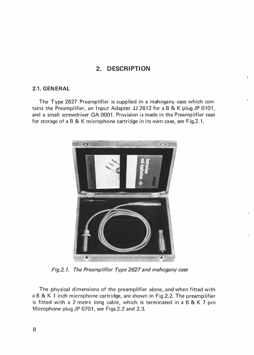
2.1. GENERAL
The
Type
2627 Preamplifier
is
supplied in a mahogany
case
which con-
tains the Preamplifier,
an
Input
Adapter
JJ
2612
for
a B & K plug
JP
0101,
and
a small screwdriver
OA
0001. Provision
is
made in
the
Preamplifier
case
for
storage
of
a B & K microphone cartridge in its
own
case,
see
Fig.2.1.
Fig.2.
1.
The
Preamplifier Type
2627
andmahogany
case
The physical dimensions
of
the preamplifier alone, and when
fitted
with
a B & K 1 inch microphone cartridge,
are
shown in Fig.2.2. The preamplifier
is
fitted
with
a 2 metre long cable, which
is
terminated in a B & K 7
pin
Microphone plug
JP
0701,
see
Figs.2.2
and
2.3.
8

Fig.2.2.
The
Preamplifier Type 2627,
with
and
without
the 8 & K 1inch
microphone,
and
7
pin
plug
(dimensions
in
mm)
Thread
for
Microphone
Polarization
Voltage
Ground
(Heating element)
Signal
Casing
to
outer
screen
Looking
at
pins
from
outside
120
V DC
Supply
Heating element
Fig.2.3. Pin connection
of
output
plug
The preamplifier connects
directly
to
the PREAMP. INPUT
of
most
of
the B & K Measuring Amplifiers, Frequency Spectrometers,
and
the
Real
Time Analyzer. The preamplifier
input
socket on
these
instruments delivers
9
all
the
necessary voltages for
the
preamplifier,
and
the
200
V
polarization
voltage
for
a B & K
microphone
cartridge. When
the
preamplifier
is
used
with
certain
B& K
instruments,
e.g.
Types
2606/07,2113/14,3347
etc.,
the
insert calibration voltage
is
also supplied via
this
socket,
see Insert Voltage
Calibration,
chapter
3.
The
preamplifier
may
be used
with
other
B & K
instruments
with
a suitable
input
socket
providing
the
insert voltage
capability
is
not
required. If
this
feature
is
required,
the
Insert Voltage
Junction
Box ZH
0007
must
be
inserted
between
the
preamplifier
and
the
measuring
instrument,
see
section
3.2.
The
preamplifier
contains
a high
impedance
input
stage coupled with a
field
effect
transistor,
and a low
impedance
output
stage.
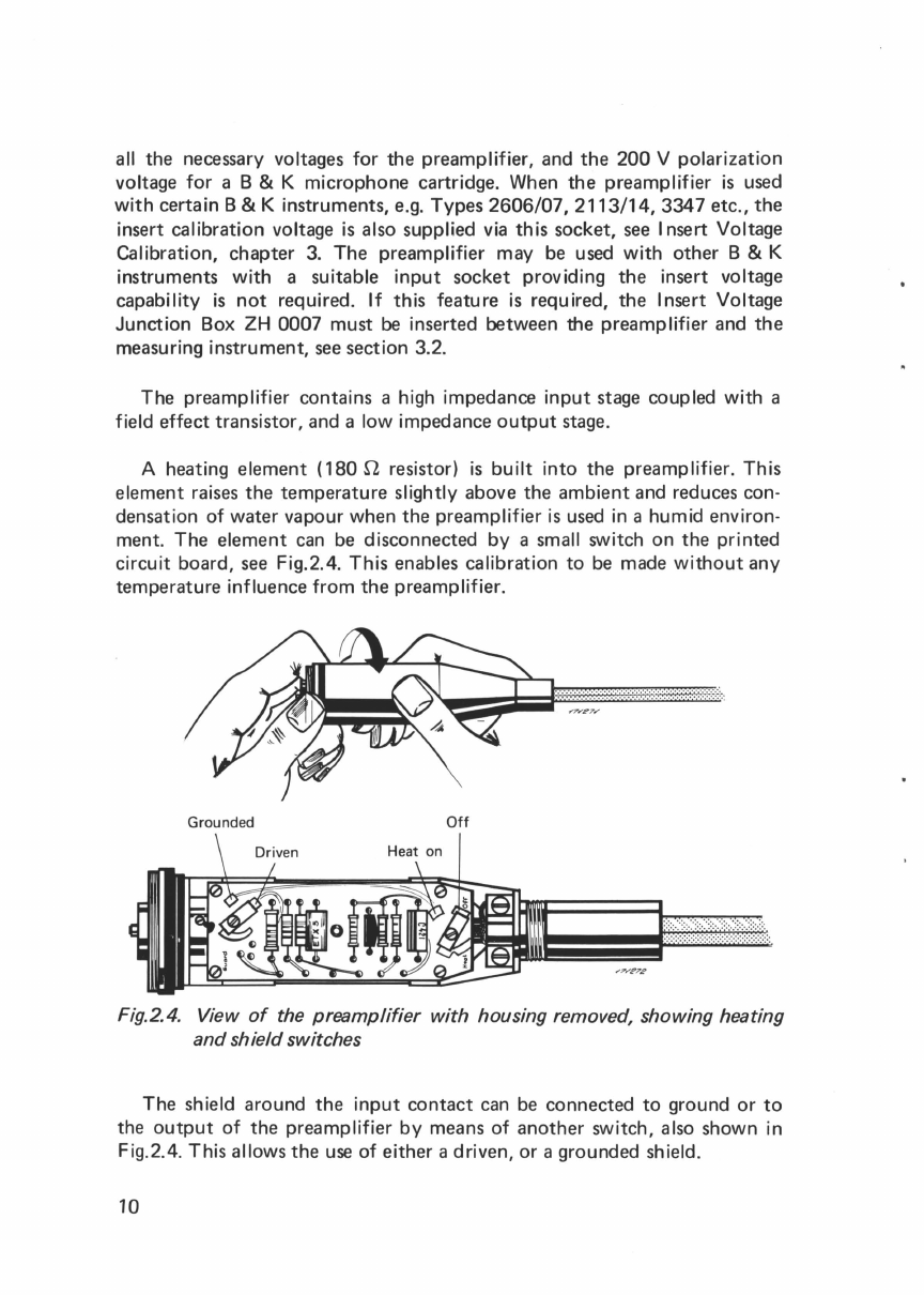
A heating
element
{
180
Q resistor)
is
built
into
the
preamplifier.
This
element
raises
the
temperature
slightly
above
the
ambient
and reduces con-
densation
of
water
vapour
when
the
preamplifier
is
used
in
a humid environ-
ment.
The
element
can be
disconnected
by
a small switch
on
the
printed
circuit
board,
see Fig.2.4.
This
enables calibration
to
be made
without
any
temperature
influence
from
the
preamplifier.
Grounded
Off
Fig.2.4. View
of
the
preamplifier
with
housing removed, showing heating
and
shieldswitches
The
shield
around
the
input
contact
can be
connected
to
ground
or
to
the
output
of
the
preamplifier
by
means
of
another
switch, also shown in
Fig.2.4. This allows
the
use
of
either
a driven,
or
a
grounded
shield.
10

The
driven shield will minimize
the
stray capacitances, and hence reduce
the
input
capacitance
of
the
preamplifier. If
the
driven shield arrangement
is
used,
the
open
circuit voltage
produced
from
a
microphone
by a known
sound
pressure level differs by less
than
0.02
dB
from
the
open
circuit
voltage which
would
be
obtained
if
the
shield were grounded (ASA
51.10-1966).
The
choice
of
the
configuration
is
necessary
to
be
in
agree-
ment
with
different
methods
used
in
Standards
laboratories.
Access
to
the
switches
is
gained by unscrewing
the
housing
of
the
preamplifier, see Fig.2.4.
The
switches are
then
operated
by
loosening
the
small screw
with
the
screwdriver provided,
and
resetting
the
link
to
the
position required, see Fig.2.4.
The
screw
is
then
retightened, taking care
not
to
move
the
link
from
its desired position.
Note:
The
supplies
to
the
preamplifier should
be
disconnected
before
the
housing
is
removed.
The
supplies
to
the
preamplifier
should
also
be
discon-
nected
before
a
transducer
is
connected
to
the
preamplifier.
The
construction
of
the
preamplifier
is
such
that
stray capacitances, and
leakage resistance are
kept
to
a
minimum.
A
double
screening ensures a very
low cross
talk
between
insert voltage line
and
preamplifier.
The
input
con-
tact
is
spring loaded,
and
gold plated,
to
ensure
the
best
possible electrical·
connection
and low
contact
noise level.
The
polarization voltage for a
condenser
microphone
cartridge
is
supplied
through
a long
time
constant
charging circuit.
After
switching
on,
or
after
changing cartridges, several seconds should
be
allowed
for
the
cartridge
to
charge up.
When
the
preamplifier
is
dispatched
from
the
factory,
the
switches are
set
with
the
heating
element
disconnected,
and
the
shield
around
the
input
contact
in
the
driven position.
2.2. CHARACTERISTICS
2.2.1.
Input
characteristics
The
preamplifier has a very high
input
impedance which
is
relatively
independent
of
temperature
over its
operating
range.
The
input
capacitance
is
dependent
on
whether
the
shield
around
the
input
contact
is
grounded
or
driven.
11
The
input
impedance
with
driven shield
is
greater than
10
Gn
in parallel
with
less
than 0.5 pF. The
input
impedance
is
greater than 10
Gn
in parallel
with
less
than 5.0 pF. The figures apply
for
the whole
working
temperature
range
of
-1
0°C
to
+ 55°C.
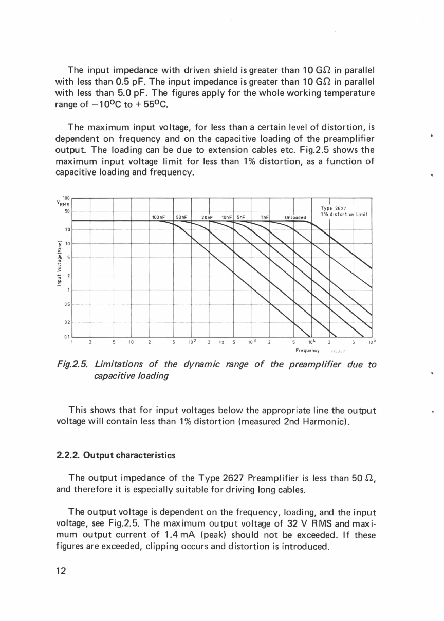
The
maximum
input
voltage,
for
less
than a certain level
of
distortion,
is
dependent on frequency and on the capacitive loading
of
the preamplifier
output.
The loading
can
be
due
to
extension cables etc. Fig.2.5 shows the
maximum
input
voltage
limit
for
less
than
1%
distortion,
as
a
function
of
capacitive loading and frequency.
100
.....---.-----,----.---r----r---r---r--r---r--,..----r--.---,----r----,
VRMS
50
0.5 -
0.2 -
0.1
'-----'------J----'-_.......__
_
___.__......._____..
__
.._____._-:---'--~-....._,_-~--'---'"'---'
1
10
2
Hz
5
Frequency
Fig.2.5.
Limitations
of
the dynamic range
of
the
preamplifier
due to
capacitive loading
This shows
that
for
input
voltages below the appropriate line the
output
voltage
will
contain
less
than
1%
distortion
(measured 2nd Harmonic).
2.2.2.
Output
characteristics
The
output
impedance
of
the
Type
2627 Preamplifier
is
less
than 50 n,
and
therefore
it
is
especially suitable
for
driving long cables.
The
output
voltage
is
dependent on the frequency, loading,
and
the
input
voltage,
see
Fig.2.5. The
maximum
output
voltage
of
32 V RMS
and
maxi-
mum
output
current
of
1.4 rnA (peak) should
not
be
exceeded.
If
these
figures are exceeded, clipping occurs and
distortion
is
introduced.
12

2.2.3. Frequency response
The
frequency
response
of
the
Type
2627
Preamplifier with a
50
pF
transducer
capacitance,
is
flat
within
0.5
dB over
the
range 2 Hz
to
200
kHz.
The
frequency
characteristics
of
the
preamplifier
are
shown
in
Figs.2.6
and
2.7. Fig.2.6 shows
the
frequency
response
of
the
unloaded
preamplifier.
The
upper
curve
is
for
a
transducer
capacitance
of
50
pF,
which
corresponds
to
the
B & K 1 inch
microphones.
The
lower curve
with
-6
Ill
L
Ill
-
--
j I
/
iII
Ill
I
-----
I
IIJ
-
-,--
-tl
I
lt-
........_
Ill
i I i
--
I I
fi
l
II
I
I -/-
-41-f
'·~
1--
!I I I
I II I I
1-
---
~
1
5
0p
F
-
-is
J
__:_u
·-
I I I
,I II I
I I
1-
I i
II
--;-I
I ! '
1-
1--
-I I
II
1
'--
-
-t
-:-4+
1- -
II
--
--,
! I I
--
I ' I II I I i
I I 1-Hm I I I I I
I I
II
T - -
f-
I I
0.1Hz 0.2
1lkHZ
20 100kHz
200
Frequency
Fig.2.
6.
Typical frequenGy response curve
for
the unloaded
preamplifier
2:
~------~--~~--.-~-.,-.-----,----.--~-r-.-r~rT------~
'r--.
~'............_
T
ype
............. 2627
1
~
~
=======~===t==~==t=~~=ti=+===~s
.....
j
~
====+==t==+=+=ti=~+==~===
~
80
~
------~--+--4--~~-+4-+-----
~~
~
-+--+--+-+~4-
~--
----
~
70
~
------~--+--4--~~-+4-
+-----
~
~~
~--+--+-+~4-~--
----
~
60
~
------
~--+--4--~~-+4-+-----~--
~~
~+--+-+~4-~
-----
~
50
~
-----~-+--4-
~~-+
4-
+--
-~--+
~
~-+
-+~4-~----
~
40
1---
--t---+-~--
r-~-+~+---~--+-+
"~
r-+-
~~
+-
--
~
30
t--
-----t---+-~--
r-~-+~
+------t---+
-
+--+
~~
~
4-
~----
~
.......
,
20
t--
---t---+-~-
r-~-+
~
+-
--~---+--+-
-+-+~1
'
-
~~
---
~
-~
AD 0029 30 m
1-------------
---
--
----------
--
---
-
10
r-
------t----+-
~--~
~-+,_
+-----
-t----+--+-
-+-+~~1-+-----
~
9
r-
------t----+-~--~~-+,_+------t----+--+-
-+-+~~1-+--
----
~
8
~------t--
--+--4--~~-+~+-----~---+--+--+-+
~4-~------
~
6
1-
-----
--
-----
__
_
__
--
~0_2~8
_
1l~
--
__
_
__
-1-
----
-
--
5 6 7 8 9
10
20 30 40 50 60 70 80 90 100 200
Frequency kHz
Fig.2.
7.
Upper frequency
limit
as
a
function
of
load,
with
a
50
pF
trans-
ducer capacitance
13

a 5 pF
transducer
capacitance, illustrates
the
effect
of
transducer
capaci-
tance on
the
frequency
response. Fig.2.7 shows
the
upper
frequency
limit
(-1
dB
point) as a
function
of
load, e.g.
extension
cable capacitance.
Fig.2.7
is
for
a
50
pF
transducer
capacitance.
2.2.4.
Attenuation
The
attenuation
of
the
preamplifier alone
is
less
than
0.08
dB.
The
atten-
uation
is
less
than
0.2
dB with
the
B & K 1 inch microphones.
2.2.5. Distortion
The
distortion
curve as a
function
of
input
voltage and capacitive loading
of
the
preamplifier
is
shown
in
Fig.2.5.
2.2.6. Noise
The
self generated noise spectrum
is
shown in Fig.2.8.
BrUe
l & K}f»r BrU.I & Ktcar
Br
Uel & Kj
mr
occcoocoooooooooooooococccoooooccoooooococcooccooo
BrUel
& Kjatr50
25
P
j
~"
;i
veter
Ronge:
__§Q__dB
Re
ctifl..-:_ _ loww u
....
Freq.: _ _
Hz
Wr
.
Sp.ed
:_ _
rnm
f
..c
. Paper
Sp.ed
:
_mm(.-c
.
10
75
Copenhagen
dB
dll
~c-2t
10
~v
Mi
6
i!tg
Obj
.:
t--t---
50
pF across
30
15
3
~V
mput
----=--.
· 1/3
octa
ve -
:
An
alysis
:::
20
10
1
~V
-
--105
Roc.lllo..!__
o...,____
Sign.,_ _ o 0
Qp
112~
10
20
Hz
50
100
200
Multi
ply
Frequency Scale
by
500 1000 2000 5000
10000
20000
~
0 A B C
Un
.
Zero
l.av.t:
1612/2112
A B C l in.
Fig.2.8. Typical noise spectrum with 1/3octave analysis
BOO
~30
2
15
0 0
This
is
obtained
as a
1/3
octave analysis from
20Hz
to
40kHz.
Total
noise in
the
wide band appears
at
the
right hand end
of
the
scale,
shown
weighted
with
A,
B,
and C networks, and with a linear response
20Hz
to
40kHz.
14

The
total
noise in the
range
20 Hz
to
200kHz
is
less
than
15
,uV. The
total noise in the
range
2
Hz
to
200kHz
is
less
than 50 ,uV.
2.3.
ENVIRONMENTAL
SENSITIVITY
2.3.1. Temperature
The preamplifier
will
operate satisfactorily in the temperature range
-1
0°C
to
+55°C. A heating element
is
built
into
the preamplifier. This
may
be
disconnected
if
the preamplifier and transducer
are
to
be
used
where
the temperature
rise
may
cause
problems;
for
disconnection
of
heater,
see
section
2.
1.
2.3.2.
Humidity
The preamplifier
will
operate satisfactorily
at
up
to
90%
humidity.
In
conditions
of
high
humidity,
it
may
be
advantageous
to
connect
the
heating
element
2.3.3. Vibration
Fig.2.9
shows
the noise
output
level
from
the preamplifier,
with
a
dummy
transducer (capacitance 50
pF),
when shaken
with
an
acceleration
•u.1
&
K)c:ar
•u.t
&
K;c.
Br
Uel
&
ICjc:er
OOCCCCCODDOODOOOOOODOCOOOCDDODOOODDDDDDDOOOOOOOOOO
BrUel
&
Kjcar
Potentiometer Ronve:
__
dB
Rectifi
er
:
__
lower
Li
m.
Freq.:
__
Hz
'Wr
.
Sp4Md
:
__
mmfse<.
Po~
Speoed
:
_rnnVsec.
Copenhagen 50 25 '
10
75
d8d8
M.asur
ing
Ob
j.:
-
--
20
10
0.3 mV
-
--1(5
Rae.""'"-
O.U•
-·
- -
Sign.,_ _ 0 0
OP
1124
10
20
Hz
50
100
200
Mt.lltiply
Frequency Scole
by
'
dldl
430
2
15
0 0
500 1000 2000 5000 10000 20000 40000 0 A B C
Un
.
Zero Le.el:
1612
/
2112
A B C
lin/?/
:Z.
?,S
Fig.2.9. Noise
output
from
the
preamplifier
with
a
dummy
transducer,
when subjected to an acceleration
of
1g
15

of
1 g
in
the
direction
shown
in
the
figure.
The
frequency range
is
20
Hz
to
5000Hz.
2.3.4. Acoustic Sensitivity
The
effect
due
to
acoustical
excitation
is
shown
in
F
ig
.2.1 0.
The
figure
shows
the
output
level
of
the
preamplifier
fitted
with a
dummy
transducer,
(capacitance
50
pF),
when
subjected
to
a
constant
acoustic
environment
of
120
dB SPL re 2 X 1o-5
N/m2
throughout
the
frequency
range
20
Hz
to
40kHz.
At
120
dB
sound
pressure level
the
output
is
less
than
300
J.lV.
B
ri.i
el
& Kjcar •
Meosurino
Obt-t· _
__
Br
Uel & Kioar
OOOOOOOOOOOOOOOOOODDDDDDD
DDDODODDDOOOOOD
OODDDDOOO
OD
~
Recotdlrii;JNo
.:
Sign
.:
f--j' •-+
j_
I
~
-
~
-
I
;__:!
I +
_:__
t-}
::
-r-
-_: 1,
·-
~--:
-
wH·Lit
'
r.--
--tt+-t-+-t-ttt-:--
--.
t--·
I
'-'~
- - : 30
~
v
+--
~r---+--
--+-
-
::2_:
----:--,
nl\lll-tlf-trf~
'-itt-:--+t--
-+-
+-r-+-t-'---+----l
I
f-
--! '
::!
-! -
--
- : :1:l'l-1.:
lA
; ,-;-
r==:--
_·
t= -
;-
~
-
---
~
_-
~
· · : i · :
_-,
r-- :_
--:
·
--:-
:..
+ I I:
fll
'
_,
, -,
I
f-:
_-: I I '
-I
- - . :
-w
-" t
tt
'
r---
1 - - · I · •
.JI
: H.J 1
l:-b
t-;;
a......J
#r
.. -r
~
·
I
~
____:_
~
-
I
~
: i
10
"IV
r-""'T"'
!:.':: -'
..::
-
-l
L
=-=-='
-
__
: -
j_j
.;.
!t!
'
d-
i=± -
!±±_
~
--=
i
~-----'-
-t
'
: - 1 _L
__
_
1
: -
;--.
l-==t=
~
~
·-
:-•
-·
-t-j
.,
:tl
-
--=1
I
I;-
- - I - - i
1-i
t--i-
--
r,
- ' . :
t-t--r-
t-
--t-,r-t-H-t-t-t-
- -
1
2
H1
5 20 5000 10000
20000
50000
'()()()()()
QP1141
~t
.
Ronv-
:
_
==--"
d
"-
8
_::'""'*=
·=·
'c====-.::
l-~U
=
m
.
F=._
"-=.
=='
H
.:o..
•
_:
YI
=riti=""=Spood=-=
==
-=~"
~-
-
'=•"":::.;Spood
=
·==
=
~
=:...-
_____,
(=7/
"-<27
.rt
..J
Fig.2.10. Noise
output
from
the preamplifier with a
dummy
transducer,
when subjected to an acoustic environment
of
120dB SPL
2.3.5. Magnetic Field
The
preamplifier
will
operate
satisfactorily
without
any
deviation
from
the
specifications in a
magnetic
field
of
strength up to
at
least
100
Aim.
2.3.6.
Shock
Sensitivity
The
preamplifier
is
designed
to
be largely unaffected
by
shock
con-
ditions.
It
has been
tested
with
1000
repeated
40
g
shocks
without
any
deviation
from
the
specifications.
16

3.
INSERT
VOLTAGE
CALIBRATION
3.1.
GENERAL
The
Type
2627 Preamplifier
has
been designed
to
allow
calibration
of
the
B & K 1 inch Condenser Microphone Cartridges Types 4144, 4145, and
4146, according
to
the Insert Voltage technique.
This
is
sometimes
known
as
the
"substitution"
method. The Insert Voltage calibration
can
be
used
by
comparison
with
a known sound source,
or
in connection
with
reciprocity
calibration.
These
methods
are
described in the I
EC
Recommendation
R-327, and the American Standard
ASA
S1-10-1966 on
the
calibration
of
microphones. Full details on
reciprocity
calibration can
be
found
in the
instruction manual
for
the B & K Microphone Calibration Apparatus
Type
4142. The insert voltage technique
by
comparison
with
a
known
sound source
is
described below.
3.2. PRINCIPLE OF
THE
INSERT
VOLTAGE
METHOD
The substitution, or insert voltage calibration
method,
is
used
to
measure
the open
circuit
voltage sensitivity
of
a microphone.
The
open
circuit
volt-
age
of
a microphone
is
defined
as
the
vol1:age
at
a single given frequency
which appears at its terminals when the
microphone
is
working
into
an
infinite
electrical impedance. This open
circuit
voltage can
be
determined
by
the insert voltage technique
even
when the
microphone
is
terminated in a
finite electrical impedance,
such
as
the
input
impedance
of
an
amplifier.
The
principle
of
the method may
be
explained
with
reference
to
Fig.3.1.
The condenser microphone, capacitance CM,
is
first
subjected
to
a
known sound pressure level, (position
"a"
on
the
figure). The open
circuit
voltage produced
is
E0, and the voltage
at
the
input
to
the
amplifier
is
V.
The sound source
is
then stopped. However,
for
the
validity
of
this method,
the microphone should
be
term
ina
ted in
the
same
acoustical impedance.
Therefore any couplers, etc.
used
to
connect the sound source
to
the micro-
phone, should
not
be
removed.
A source of known and adjustable voltage, Ec,
is
then connected in
series
with
the microphone. This insert voltage
is
adjusted
unti
I the
input
voltage
17

to
the
amplifier
is
the
same (V) again. Then E0 =
Ec
and the open
circuit
voltage
sensitivity
can
be
calculated
as
follows:
Open
Circuit
Voltage
Sensitivity
=
dEc
soun pressure
b
~
...........
~
-o
0
Fig.3.
1.
Insert voltage calibration
of
a microphone
3.2.1. Use
with
B & K
equipment
with Insert Voltage Calibration Facility
When
the
Type
2627
Preamplifier
is
used
with
B & K
equipment
which
have
insert voltage
calibration
facility,
e.g.
Measuring
Amplifiers
2606, and
2607,
the
insert voltage
Ec
can
be
supplied in
two
ways
by:
a)
The internal reference oscillator
of
the Measuring
Amplifier
which
can
be
used
to
give a voltage at a frequency
of
1 kHz
or
b)
an
external generator such
as
the B & K Beat Frequency Oscillator
1022,
which
can give a voltage
at
any frequency
within
the range
20
Hz
to
20
kHz.
It
is
also necessary
to
have a sound source
of
known
pressure level and
frequency.
This
can be
provided
in
two
convenient ways:
18
a)
The B & K Sound Level Calibrator
Type
4230 produces a signal
at
1 kHz,
94
dB
SPL, and may
be
used
when the insert voitage
is
sup-
plied
by
either
the
internal reference oscillator,
or
by
an
external
generator.
Table of contents
Other B&K Amplifier manuals


