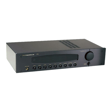
B&K Phono10 User manual

P/N12839 0902
B&K
SB!IMPLY ETTER
B&K Components, Ltd.
Phono 10
Owner’s Manual

iii
TABLE OF CONTENTS
Table of Contents...................................................................................................................................iii
Safety Precautions .................................................................................................................................1
Introduction.............................................................................................................................................2
Features...................................................................................................................................................2
Rear Panel View ......................................................................................................................................3
Design and Construction .......................................................................................................................4
Phono 10 Connections...........................................................................................................................4
Phono Stage ............................................................................................................................................5
Selecting Moving Magnet / Moving Coil ...............................................................................................................................5
Capacitive Loading .................................................................................................................................................................6
Resistive Loading....................................................................................................................................................................6
Control I/O Connections.........................................................................................................................8
Gain Switch .............................................................................................................................................9
Digital Output ..........................................................................................................................................9
Troubleshooting....................................................................................................................................10
Care and Cleaning ................................................................................................................................10
Specifications .......................................................................................................................................11
Limited Warranty..................................................................................................................................................................12
Returning Equipment ............................................................................................................................................................12
WWW.BKCOMP.COM ...........................................................................................................................13

1
SAFETY PRECAUTIONS
PLEASE READ BEFORE INSTALLING
WARNING: to prevent fire or shock hazard, do not expose this unit to rain or moisture. Care should be
taken to prevent objects or liquid from entering the enclosure. Never handle the power cord with wet
hands.
•The lightning flash with arrowhead, within an equilateral triangle, is intended to alert the user of the
presence of uninsulated “dangerous voltage” within the product’s enclosure that may constitute a risk of
electric shock to you.
•The exclamation point within an equilateral triangle is intended to alert the user of the presence of
important operating and maintenance (servicing) instructions in the literature accompanying the unit.
•Observance of polarity is essential. Double-check connections before turning the receiver or preamplifier
on. The Phono 10 can be damaged if polarities are incorrect.
•Turn your receiver or preamplifier and Phono 10 ‘off’ before plugging in or unplugging cables!!!
•The Phono 10 is equipped with raised feet. They help to keep acoustic feedback into the unit at a
minimum. They also provide a measure of protection against scratching any surface the unit might be
resting on. Do not alter or remove them.
•Do not stack anything on top of the Phono 10 (preamplifier, processor, source...etc.).
•Always unplug the Phono 10 from the AC power source before removing the top cover and making any
changes to the Moving Coil (MC) or Moving Magnet (MM) stage inside the unit. Important!

2
INTRODUCTION
Thank you for selecting B&K Components, Ltd.’s Phono 10 phono preamplifier. The Phono 10 is a discrete circuit
DC coupled topology RIAA phono preamplifier. It features a selectable head amp for use with both Moving Coil
(MC) and Moving Magnet (MM) players. In addition to a control I/O circuit is incorporated for standby / turn-on
from an external device there is also a S/PDIF coax digital output for use with CD quality recording. Gold plated
connectors have been utilized to minimize degradation in the signal path. In order to obtain maximum
performance from this unit, please read the following instructions very carefully. Again, we at B&K Components,
Ltd. would like to thank you for purchasing a Phono 10 preamplifier and wish you many years of listening
pleasure.
FEATURES
1% Metal Film Resistors - High quality resistors allow a lower noise floor and better sound.
Control I /O - Circuit allows for power ‘on’ and ‘off’ muting and external control for other components.
Direct coupled output - Provides a full and accurate, three dimensional reproduction of source material.
Discrete Circuitry – Allows minimum loading of the Phono cartridge and maximum amplification dynamic range.
FET loading – Allow maximum linearity with minimum noise.
Gold Plated Connectors – Provides for minimum signal loss and degradation.
Optional Digital output – Allows the Phono 10 to be used for transferring records to your Computer, CD or DAT
player. If not currently installed in the Phono 10, the S/PDIF *Digital output board is available for upgrade.
RIAA accuracy - +/- .2 dB through the use of polypropylene film capacitors. This produces a transparent sound
with highly accurate musical timbre.
Toroidal Transformer - Efficient, high current, shielded transformer that supplies the amplifier with a clean and
constant supply of power, even during highly demanding source material passages.
Wide bandwidth - Assures clear reproduction with all styles of music.

3
REAR PANEL VIEW
Phono 10 Rear Panel
AC Receptacle Digital
Output
Ground
Binding
Post
Left and Right
Analog Inputs
Left and Right
Analog Outputs
Gain
Switch
Control I /O
7
6
5
4
3
21
CAUTION
RISK OF ELECTRIC SHOCK
DO NOT OPEN
RISK OF ELECTRIC SHOCK
DO NOT OPEN AC IN
voltage
B&K
WS S B .
E IMPLY OUND ETTER
WS S B .
E IMPLY OUND ETTER
SER. NO.
B&K Components, Ltd.
Made in the U.S.A.
B&K Components, Ltd.
Made in the U.S.A.
www.bkcomp.com
LEFT OUTPUT
RIGHT OUTPUT
LEFT INPUT
RIGHT INPUT
GNDDIGITAL
OUT
DIGITAL
OUT
0dB
-10dB
GAIN
+
CONTROL
I/O
CONTROL
I/O
DEFEAT
ENABLE
OUT
IN
+ + ++
++
12V
35mA
1. Control I / O 5. Ground Binding Post
2. Gain Switch 6. Digital Output
3. Analog Outputs 7. AC Receptacle
4. Analog Inputs
1. Control I /O - For remote turn on from receiver or preamplifier.
2. Gain Switch - Adjusts the output level by 10 dB. Allows matching the output level to other source levels.
3. Analog Outputs - Connect the Phono 10 to a receiver or preamplifiers analog input.
4. Analog Inputs – Connect a Phono Player to the Phono 10.
5. Ground Binding Post - For connecting ground from a Phono Player to the Phono 10.
6. *Digital Output – Connect the Phono 10 to a S/PDIF coax digital input for playback and/or recording.
7. AC Receptacle - For attaching the supplied AC power cord to the Phono 10.
*Digital output is an option (Upgradable)

4
DESIGN AND CONSTRUCTION
The Phono 10 utilizes high quality electronic circuitry to achieve an environment wherein a detailed, transparent
and highly musical sound can be realized. The high quality parts complement includes state-of-the-art solid state
devices, 1% metal film resistors, polypropylene capacitors and a low noise toroidal transformer.
PHONO 10 CONNECTIONS
All leads should be connected securely to the input and output terminals. Loose connections can lead to impaired
performance, noise interference and possible damage to your equipment. When making connection changes of
any sort (reinserting input lead pins, changing phono cartridges, etc.), be sure to first turn your receiver or
preamplifier's power off as well as the Phono 10’s power (light indicator off). Typical interconnections are
illustrated in Figure 1.
Figure 1
NOTE: A grounding post is provided for connection to the phono player.

5
PHONO STAGE
The phono stage of the Phono 10 may be configured for either Moving Magnet (MM) or Moving Coil (MC)
applications with the additional capability to set the resistive and capacitive loading of the phono cartridge. Note:
Your Phono 10 has already been configured for a MM stage with a resistive load of 50 Kohms. You do not have to
perform any modifications unless you so desire. To reconfigure your Phono 10, follow the appropriate procedure
listed below.
IMPORTANT - ENSURE THAT THE POWER CORD IS DISCONNECTED FROM THE AC
OUTLET PRIOR TO PERFORMING ANY OF THE FOLLOWING PROCEDURES!
SELECTING MOVING MAGNET / MOVING COIL
1. Locate the 2-position slide switch on the inside of the unit (see Figure 2). It is located near the back left side
with the front of the unit facing you. The switch can be identified by its blue color and white tab in the center. MC
and MM are labeled on the board on either side of the switch.
2. Slide the center white tab left or right to select the type of phono stage that is desired.
Left = Moving Coil (MC), Right = Moving Magnet (MM).
NOTE: The Phono 10 is shipped from the factory with the phono stage set to the MM configuration and a resistive
load of 50 Kohms. Selecting the MC stage without changing the resistive loading (see “Resistive Loading”) will
result in an effective load of 133 ohms.
Figure 2

6
IMPORTANT - ENSURE THAT THE POWER CORD IS DISCONNECTED FROM THE AC OUTLET PRIOR
TO PERFORMING ANY OF THE FOLLOWING PROCEDURES!
CAPACITIVE LOADING
NOTE: The Phono 10 is shipped from the factory with no capacitor installed. Typically, the capacitance of the
phono cables (Cphono cables) is sufficient and no capacitor is needed.
The capacitance (Cload) should be:
Cload = Ccartridge - Cphono cables - 75 pF
1. Determine the capacitor value (pF) for proper loading of the MM cartridge in accordance with the
specifications of the cartridge you have selected. The manufacturer of the cartridge may suggest a
recommended value. The capacitive loading affects both the MM and MC stage.
2. With the front of the unit facing you, locate the two gold plated pin receptacles with the label “CLOAD”
between them. They are located near the back left of the circuit board.
3. Trim the leads of the capacitors (one per channel) to approximately 3/8 inch.
4. Insert the leads into the “CLOAD” pin receptacles securely.
RESISTIVE LOADING
NOTE: The Phono 10 is shipped from the factory with a 100K ohm resistor installed and the phono stage MM
configuration selected (see “Selecting Moving Magnet / Moving Coil”). This resistor should not be removed
unless the resistive loading is being changed in accordance with the following guidelines.
1. Determine the resistor value for proper loading of the cartridge in accordance with the specifications of the
cartridge you have selected. The manufacturer of the cartridge may suggest a recommended value. The
resistive loading affects both the MM and MC stage. The factory installed resistors in the Phono 10 will match
most phono cartridges on the market.
IMPORTANT - ENSURE THAT THE POWER CORD IS DISCONNECTED FROM THE AC OUTLET PRIOR
TO PERFORMING ANY OF THE FOLLOWING PROCEDURES!
A. The resistive loading for the MM stage can be calculated using the following equation:
Ri (in Kohms) = (100,000 * Rc) / (100,000 - Rc)
Where:Ri = inserted resistor value
Rc = cartridge loading value (must not exceed 100 Kohms)
**1 Kohms = 1,000 ohms **
For example:
Rc (desired) = 50 Kohms
Ri = (100,000 * Rc) / (100,000 - Rc)
Ri = (100,000 * 50,000) / (100,000 - 50,000)
Ri = 100 Kohms (factory installed)
Refer to (Table 1) for more examples.
B. The resistive loading for the MC stage can be calculated using the following equation:
Ri (in ohms) = (133 * Rc) / (133 - Rc)
Where:Ri = inserted resistor value
Rc = cartridge loading value (must not exceed 133 ohms)
ForRi >> 1300, Rc = 133 ohms
For example:
Rc (desired) = 100 ohms
Ri = (133 * 100) / (133 - 100)
Ri = 403 ohms (use 402 ohm standard value resistor)
Refer to (Table 1) for more examples.

7
Table 1
Resistive Loading
Examples
Rc desired
(Ohms)
Ri calculated
(Ohms)
Ri standard
(Ohms)
25 30 30.1
45 68 68.1
75 171 169
100 403 402
MC
125 2.1 k 2.10 k
5.0 k 5.3 k 5.36 k
20.0 k 25.0 k 24.9 k
35.0 k 53.8 k 53.6 k
50.0 k 100.0 k * 100 k
MM
75.0 k 300.0 k 301 k
* Factory Installed
2. With the front of the unit facing you, locate the two gold plated pin receptacles with the label “RLOAD” between
them. They are located near the back left of the circuit board. (See Figure 3)
3. Trim the leads of the resistors (one per channel) to approximately 3/8 inch.
4. Insert the leads into the “RLOAD” pin receptacles securely.
Figure 3

8
CONTROL I/O CONNECTIONS
A control input/output is provided on the Phono 10 preamplifier to remotely turn the unit on and off. A receiver or
preamplifiers control output, such as is provided with the B&K series, can be utilized to provide a control signal to
the Phono 10. If a B&K amplifier is also being used, the control signal can be extended to include each
successive component by simply running a 1/8 inch mini jack cable from the CONTROL OUT connector of the
Phono 10 to the CTRL IN connector of the amplifier. This is commonly referred to as “daisy chaining”. An example
of how to connect these components is illustrated in Figure 4.
If a source other than a B&K receiver or preamplifier is used to control the Phono 10, only the control output
voltage from the source is critical. It must be within the range, as indicated on the rear panel, 5 - 24V DC. The
Phono 10’s CONTROL OUT will provide each successive component with a control voltage of 12V DC for reliable
operation. The Phono 10’s control output may be used as a source of 12V DC @ 35 mA for other user
applications as well. DO NOT POWER MOTORS WITH THIS CIRCUIT!
Figure 4
If the control function is desired, each component in the system must remain connected at all times and the
control must be enabled. To enable the control function, the CONTROL ENABLE button must be out for each
controllable component in the system. For more information on the Phono 10’s output status under various control
conditions, refer to (Table 2).
Table 2
@ CTRL IN Button Position Output Status @ CTRL OUT
Signal OUT Sound Signal
Signal IN Sound Signal
No Signal OUT Mute No Signal
No Signal IN Sound Signal
NOTE: The control voltage is for muting control only. Each component must be connected to its own source of AC
power in order for it to operate.

9
GAIN SWITCH
A gain switch is provided on the Phono 10 to help match the Left and Right output level to that of the other
sources in the system. This is useful in maintaining a constant volume level of the receiver or preamplifier when
selecting different sources. When the switch is “IN”, the output signal level is 0 dB. When the switch is “OUT”, the
output level is decreased by 10 dB.
NOTE: If the Phono 10 has Digital Output capability the digital output level is related to the setting of the gain
switch.
DIGITAL OUTPUT
An RCA, coaxial, *Digital Output is provided on the Phono 10. It outputs a 44.1 kHz, 24 Bit signal for CD quality
recording. The digital output level is related to the setting of the gain switch.
A typical connection is shown below:
Figure 5
*Digital output is an option (Upgradable)

10
TROUBLESHOOTING
PROBLEM POSSIBLE CAUSE POSSIBLE SOLUTION
No sound
(‘On’ LED not
illuminated)
1. Power cord not plugged in
2. Power off at AC source
3. AC power inlet fuse blown or faulty
4. Control switch in the wrong position
1. Reconnect power cord
2. Check AC switch or fuse
3. Check for shorts or overloading
4. Place control switch in proper position
(Page 8)
No sound on 1 or
both channels
(‘On’ LED
illuminated)
1. Source to Phono 10 cables loose or
faulty
2. Phono 10 to preamplifier cables loose
or faulty
3. Input not correctly selected on
preamplifier / receiver
1. Tighten, repair or replace cable
2. Tighten, repair or replace cable
3. Check source settings on
preamplifier / receiver
Loud hum or buzz
on one or more
channels
1. Poor ground connections in
interconnect cables
2. Poor ground in main AC supply
3. Cables running near AC power cords
4. Phono ground not connected
between phono player and Phono 10
1. Check all connectors and repair as
necessary
2. Check ground of outlet. Have it checked
by qualified serviceman
3. Reposition cables
4. Connect phono ground
Sound is lower in
volume compared
to other sources
1. Gain switch is in the low output level
setting
2. MC / MM switch in wrong position
according to cartridge type
1. Check setting of the Gain Switch (Page 9)
2. Check setting of MC / MM switch (page 5)
Sound is distorted
on 1 or both
channels
1. LOAD capacitors or resistors installed
improperly or missing
1. Check LOAD capacitors and / or resistors
for proper installation
* *Note:If unit continues to blow power inlet fuses, DO NOT USE A HIGHER RATED
FUSE, please contact customer service to have the unit serviced.
CARE AND CLEANING
Under normal use, the Phono 10 will not require any special care. Clean the exterior of the unit by wiping it with a
damp cloth to remove any dirt or dust that accumulates. Do not let any liquid enter the amplifier through its vents
or top cover. It is recommended that the connectors on the rear panel be cleaned annually using isopropyl
alcohol.

11
SPECIFICATIONS
Moving Coil Sensitivity (at 1 kHz)
.09 mV
Moving Coil Overload (at 1 kHz)
17 mV
Moving Coil Load Resistance
Variable
Moving Coil Capacitance
Variable
Moving Coil (S/N A Weighted)
78 dB
Moving Magnet Sensitivity (at 1 kHz)
.8 mV
Moving Magnet Overload (at 1 kHz)
225 mV
Moving Magnet Load Resistance
Variable
Moving Load Capacitance
Variable
Moving Magnet (S/N A Weighted)
89 dB
Input Impedance
50 k Ohms
Output Impedance
221 Ohms
Maximum Output Level
9 V RMS
Frequency Response
5 Hz - 20 kHz
Digital Output
44.1 kHz / 24 bit
Digital Output (S/N A Weighted)
95 dB
Dimensions in Inches
Width 17
Height 2¼
Depth 8½
Shipping Weight (lb.)
8.5
Power Consumption
10 watts / .1 amps
Replacement Fuse
.5 Amp/250 Volt Fast Blow
Specifications and design are subject to change at any time without notice.

12
LIMITED WARRANTY
B & K Components Ltd., referred to herein as B & K, warrants your B & K equipment against all defects in
material and workmanship for a period of five years from the date of purchase. This warranty applies only to the
original purchaser and only to equipment in normal residential use and service. Defective equipment must be
returned to B & K, prepaid, accompanied by proof of purchase and sufficient payment to cover the cost of return
shipping and handling, and will be repaired or replaced at the discretion of B & K whose decision as to the method
of reparation will be final.
This warranty shall not apply to any equipment which is found to have been improperly installed, incorrectly fused,
misused, abused, or subjected to harmful elements, used in any way not in accordance with instructions supplied
with the unit, or to have been modified, repaired or altered in any way without the expressed, written consent of
B&K. This warranty does not apply to the cabinet or appearance items such as the faceplate or control buttons,
nor does it cover any expenses incurred in shipping the unit to and from the manufacturer’s service depot.
This warranty on B & K Components, Ltd. products is NOT VALID if the products have been purchased from an
unauthorized dealer or an E-tailer or if the original factory serial number has been removed, defaced or replaced
in any way. B & K Components, Ltd. sells its products through authorized dealers in order to insure that
consumers obtain proper dealer service and support. Buying from an authorized B & K Components, Ltd. dealer
insures that you have a FACTORY WARRANTY on your B & K Components, Ltd. product. If you have any
questions concerning your Factory Warranty call B & K Components, Ltd. at 716-656-0023.
Upgradability: B & K is one the first manufacturers in the audio/video industry to consistently offer software and
hardware upgrades to its processing of audio signals. Through upgrades B & K delivers exceptional value to its
customers. But what is “Upgradability”? Upgradability is not a guarantee; we define it as a philosophy of designing
and manufacturing products so that as audio technology evolves, B & K can provide enhancements and
improvements to its products that are economically viable.
THE EXPRESS FACTORY WARRANTY HEREIN CONTAINED IS IN LIEU OF ANY AND ALL OTHER
WARRANTIES, EXPRESSED OR IMPLIED, INCLUDING ANY WARRANTY OF MERCHANTABILITY,
UPGRADABILITY OR OF FITNESS FOR ANY PARTICULAR PURPOSE. B&K COMPONENTS, LTD. SHALL
NOT UNDER ANY CIRCUMSTANCES BE LIABLE FOR DAMAGES, INCLUDING SPECIAL, INCIDENTAL,
EXEMPLARY, PUNITIVE OR CONSEQUENTIAL DAMAGES ARISING OUT OF OR IN CONNECTION WITH
THE PURCHASE, USE OR PERFORMANCE OF ANY B&K PRODUCT.
This warranty gives you specific legal rights. Your may also have other rights which vary from State to State.
Some States do not allow the exclusion or limitation of incidental or consequential damages and the foregoing
exclusions may not apply to you.
No agent, representative, dealer or employee of B&K has the authority to increase or alter the obligations or terms
of this warranty.
RETURNING EQUIPMENT
No equipment may be returned to B&K Components Ltd. without a RETURN AUTHORIZATION (RA). Should you
find it necessary to return equipment to B&K, for any reason, a RETURN AUTHORIZATION (RA) number must be
issued by B&K in respect of the equipment being returned. You may request an RA number by calling B&K at the
numbers below. We will need the following information to issue your RA number. Please have it ready before you
call.
1. Your name, address, and phone number.
2. The model and serial number of the equipment being returned.
3. A description of the problem being experienced.
4. Your sales receipt.
Your call will be referred to a Technical Service Representative who will work with you to resolve the problem. If it
is determined that the unit must be returned for repair, an RA number will be issued.
B&K Components, Ltd., 2100 Old Union Road, Buffalo New York 14227-2725
Phone 1-800-543-5252 or (716) 656-0026, Fax (716) 656-1291

13
WWW.BKCOMP.COM
B&K Components, Ltd.
2100 Old Union Road
Buffalo, New York 14227
Phone: 716 – 656 - 0026
Table of contents
Other B&K Amplifier manuals
Popular Amplifier manuals by other brands

Audio Control
Audio Control LC-6.1200 manual

Audio Control
Audio Control Bijou 600 installation manual
Taramp's
Taramp's MD 800.1 instruction manual

Bluesound
Bluesound Powernode Quick setup guide

PerkinElmer
PerkinElmer 5182 instruction manual
Diamond Audio Technology
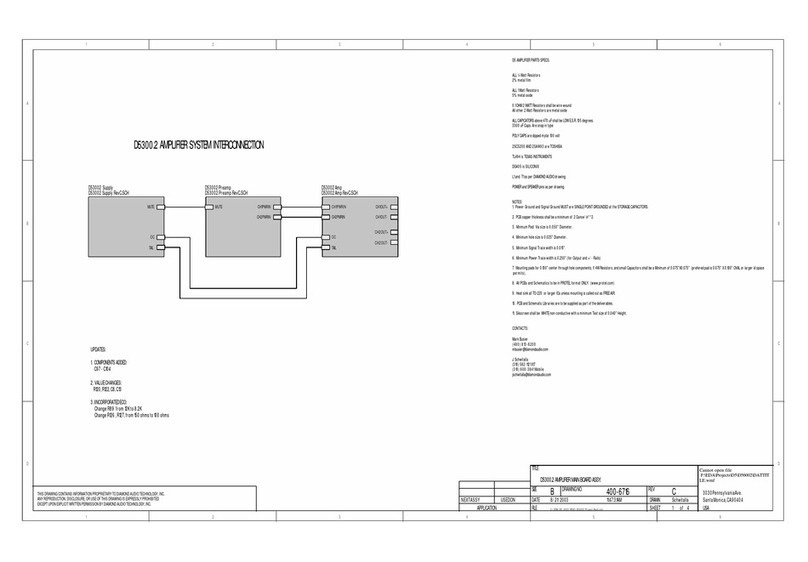
Diamond Audio Technology D5 300.2 Schematic diagram

