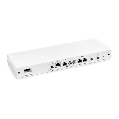
Bang & Olufsen Beomaster 5500 User manual

Beomaster
5500
Owner’s
manual

How
to
use
this
manual
This
manual
explains
how
to
set
up
the
Beomaster
5500
receiver
and
how
to
use
the
few
controls
available
on
the
front
panel.
@
It
gives
a
detailed
description
of
all
the
@
It
also
explains
the
meaning
of
the
cues
on
the
sockets
on
the
rear
and
for
which
purposes
display
panel
on
the
front.
they
must
be
used.
For
detailed
operating
instructions,
please
refer
to
the
Master
Control
Panel
5500
manual.
©
Bang
&
Olufsen
1987

Where
to
put
the
Beomaster,
4
Connections,
6
Stand-by
mode,
8
How
to
use
the
controls,
9
Displayed
cues
and
symbols,
10
Connecting
headphones,
11
Technical
specifications,
12

Beosystem
5500

The
Beosystem
5500
1s
easy
and
very
convenient
to
use
-
you
can
in
fact
operate
the
whole
system
without
leaving
your
chair.
The
Master
Control
Panel
5500
is
the
key
to
the
system
and
it
communi-
cates
with
the
brain
of
the
system,
the
Beomaster
5500.
Together
they
form
the
basis
of
the
system.
The
other
units
in
the
system,
the
Beocord
5500,
the
Beogram
5500
and
the
Beogram
CD
5500,
are
modules
with
which
you
can
extend
your
Beosystem
5500.
The
Beomaster
5500
1s
a
so-called
Beolink
product,
which
means
that
it
can
be
used
as
a
master
in
a
Bang
&
Olufsen
Beolink
system.
In
a
Beolink
system
video
and
audio
products
are
interconnected
and
they
can
be
operated
using
only
one
remote
control
unit
—
the
Beolink
1000.
For
further
information
about
setting
up
and
operating
the
Beolink
system,
please
refer
to
the
special
Beolink
manuals.

4
Where
to
put
the
Beomaster
where
ventilation
cannot
be
impeded.
Avoid
placing
it
in
direct
sunlight
or
near
radiators
or
ar
other
sources
of
heat.
If
your
Beosystem
includes
other
units,
you
The
Beomaster
must
be
placed
horizontally
on
a
can
place
them
on
top
of
each
other,
as
in
a
rack
stable
surface.
Make
sure
to
put
it
in
a
place
system,
or
next
to
one
another.
The
Beomaster
must
be
placed
so
that
the
control,
e.g.
to
allow
communication
round
distance
from
the
the
Master
Control
Panel
is
no
corners,
you
can
connect
a
specially
designed
longer
than
25
metres.
Make
sure
that
they
can
sensor.
The
sensor
(type
no.
2001)
is
available
communicate
with
each
other.
from
your
Bang
&
Olufsen
dealer.
If
you
want
to
extend
the
range
of
remote
SENSOR

Before
putting
the
Beomaster
in
its
final
place,
connections
required
(see
the
following
make
sure
that
you
have
carried
out
all
the
paragraph).
AM
—ti
oo—
1
SPEAKERS
1
FM
—a
gWo—
R

Connections
Connect
loudspeakers,
antennae,
and
the
other
units
in
the
Beosystem,
if
any,
to
the
Beomaster
before
connecting
it
to
the
mains
supply.
@
FM:
|
Sockets
for
240
ohm
or
75
ohm
FM
antenna.
@
AM:
Socket
for
AM
antenna.
@
PHONO:
7
pin
DIN
socket
for
the
Beogram
5500,
or
any
other
Bang
&
Olufsen
record
player
with
a7
or
5
pin
DIN
plug.
@
CD:
7
pin
DIN
socket
for
the
Beogram
CD
5500
compact
disc
player.
To
gain
access
to
the
sockets,
lift
up
the
hinged
grille
at
the
rear.
SPEAKERS
1
PHONO
TAPE
2/AUX
pu
L
R
SENSOR!
SPEAKERS
2
TAPE
@
TAPE
2/AUX:
7
pin
DIN
socket
for
-
auxiliary
Bang
&
Olufsen
‘ae
recorder
with
a7
or
5
pin
DIN
plug,
or
-
Beovision
LX
2800/2500
or
LX/L
2802/2502.
@
TAPE:
7
pin
DIN
socket
for
the
Beocord
5500,
or
any
other
Bang
&
Olufsen
tape
recorder
with
a
7
or
5
pin
DIN
plug.
@
Earthscrew.

@
SENSOR:
6
pin
DIN
socket
for
|
-
the
Bang
&
Olufsen
Sensor
(type
no.
2001)
-
the
Bang
&
Olufsen
Remote
Mains
Switch
(type
no.
4002).
This
connection
requires
an
adaptor,
Bang
&
Olufsen
part
no.
6270349.
@
SPEAKERS
1:
Sockets
for
-
left
(L)
and
right
(R)
loudspeakers
in
the
same
room
as
the
Beomaster,
or
-
left
(L)
and
right
(R)
cable
connections
for
the
Bang
&
Olufsen
Beolab
Penta
power
amplifier/loudspeaker
module,
or
-
left
(L)
and
right
(R)
cable
connections
for
the
Bang
&
Olufsen
Beolab
150
power
amplifier.
@
PH:
Sockets
for
record
player
with
phono
plugs
-
L
for
left
channel
and
R
for
right
channel.
@
TP2/AUX
(IN/OUT):
Sockets
for
auxiliary
tape
recorder
or
compact
disc
player
with
phono
plugs
-
L
for
left
channel
and
R
for
right
channel.
@
LINE
(IN/OUT):
Sockets
for
equalizer
-
L
for
left
channel
and
R
for
right
channel.
@
SPEAKERS
2:
Sockets
for
-
left
(L)
and
right
(R)
loudspeakers
in
an
adjoining
room,
or
-
left
(L)
and
right
(R)
cable
connections
for
a
Master
Control
Link
installation.
@
PRE
AMP:
Sockets
for
power
amplifier
-
L
for
left
channel
and
R
for
right
channel.

—68
Stand-by
mode
Once
connected
to
the
mains
supply,
the
Panel.
The
stand-by
mode
is
indicated
by
the
Beomaster
is
in
so-called
stand-by
mode
and
tiny
red
light
on
the
display
panel
on
the
front.
ready
to
be
operated
with
the
Master
Control

How
to
use
The
controls
available
are
on
the
front
panel.
STEP
PROGRAM
-
A
rapid
tap
switches
on
the
Beomaster
on
the
preset
station
you
were
last
listening
to.
-
By
tapping
repeatedly
you
can
step
through
the
preset
stations.
“TIMER”
function
If
you
programme
the
system
to
play
at
a
specific
time,
both
the
speakers
in
the
SPEAKERS
1
sockets
and
those,
if
any,
in
the
SPEAKERS
2
sockets
will
function.
However,
you
can
cut
out
the
SPEAKERS
1
socket
if
you
wish
so
that
only
the
speakers
in
the
SPEAKERS
2
sockets
will
function
when
the
system
starts
playing
at
the
specified
time.
the
controls
MUTE
@
-
A
rapid
tap
switches
on
the
unit
you
were
last
listening
to
at
the
previously
adjusted
levels.
-
A
rapid
tap
mutes
the
loudspeakers
in
the
SPEAKERS
1
sockets.
Another
rapid
tap
cuts
the
speakers
in
again.
-
A
prolonged
pressure
switches
the
Beosystem
to
stand-by
mode.
While
keeping
the
right-hand
side
of
the
panel
depressed,
tap
the
left-hand
side.
The
TIMER
OFF
cue
now
appears,
indicating
that
the
TIMER
function
is
cancelled
on
SPEAKERS
1.
To
cut
in
the
TIMER
function
again,
follow
the
same
procedure.
The
TIMER
OFF
cue
disap-
pears.

10
Displayed
cues
and
symbols
SPEAKERS
1
sockets
Indicates
preset
number,
cut
out
during
pro-
Automatic
Fine
Tuning
unprogrammed
F(M)
or
grammed
play
(AFT)
indicator
A(M)
station,
or
sound
values.
Treble
adjustment
in
progress
Bass
adjustment
in
pro-
Source
indicators
Loudness
mode
indica-
gress
tor
The
display
on
the
front
of
the
Beomaster
gives
The
cues
and
symbols
displayed
will
not
all
be
information
about
the
operational
status
of
the
visible
at
the
same
time.
system.

Connecting
headphones
The
tiny
socket
on
the
front
of
the
Beomaster
is If
you
connect
headphones,
the
speakers
in
for
headphones,
e.g.
the
Bang
&
Olufsen
Form
1
the
SPEAKERS
1
sockets
are
cut
out.
or
Form
2
headphones.
11

12
Technical
specifications
Beomaster
5500
Type
no.
2331/2332/2334/2335
Long-term
max.
output
power
IEC
2
x
110
watts/8
ohms
Power
output
20-20,000
HZ
IHF
_.
2
x
50
watts/8
ohms
Total
harmonic
distortion
IHF
<0.09%/8
ohms
20-20,000
Hz
Dynamic
headroom
1.5
dB/8
ohms
Intermodulation
IHF
<0.1%
Wideband
damping
factor:
50
Line
input
sensitivit
25
mV/47
kohms
Signal-to-noise
ratio:
PHONO
A-weighted
>78
dB
TAPE
A-weighted
>80
dB
Channel
separation
10,000
Hz 60
dB
Line
output
500
mV/1
kohm
External
power
amplifier
1
V/1
kohm
FM
range
87.5-108
MHz
FM
aerial
impedance
75
and
240
ohms
Usable
sensitivity
stereo
19
dBf-2.5
pV/75
ohms
90
dB
quieting
sensitivity
stereo
40
dBf-28
uV/75
ohms
Signal-to-noise
ratio
65
dBf
stereo
70
dB
Frequency
response
20-15,000
Hz
+1
dB
Distortion
at
65
dBf
stereo
0.2%
Intermodulation
stereo
0.1%
Stereo
channel
separation
45
dB
LW
range
150-350
kHz
MW
range
520-1610
kHz
LW
sensitivity
20
dB
S/N
ratio
80
Vv
MW
sensitivity
20
dB
S/N
ratio
60
pV

Power
supply
2331:
220
V
2332/2335:
240
V
2334:
100
V
Power
frequency
50-60
Hz
Power
consumption
Max.
225
watts
Dimensions
W
x
H
x
D
42
x
7.5
x
32.5
cm
Weight
8.5
kg
Subject
to
change
without
notice
For
the
UK
market
only
IMPORTANT
The
wires
in
the
mains
lead
supplied
with
this
The
wire
which
is
coloured
blue
must
be
apparatus
are
coloured
in
accordance
with
the
connected
to
the
terminal
which
is
marked
with
following
code:
the
letter
N
or
coloured
black.
Blue:
Neutral
The
wire
which
is
coloured
brown
must
be
Brown:
Live
connected
to
the
terminal
which
is
marked
with
As
the
colours
of
the
wires
in
the
mains
lead
the
letter
L
or
coloured
red.
may
not
correspond
with
the
coloured
markings
Ensure
that
your
equipment
is
connected
identifying
the
terminals
in
your
unit,
proceed
as
correctly.
If
you
are
in
any
doubt,
consult
a
follows:
qualified
electrician.
13

International
guarantee
This
Bang
&
Olufsen
product
carries
a
guarantee
against
defects
in
workmanship
and
materials.
It
is
a
national
guarantee,
extended
by
Bang
&
Olufsen
to
the
country
in
which
the
product
was
bought.
The
terms
of
the
guarantee
apply
principally
to
the
country
of
purchase
but
will
be
met
by
authorized
Bang
&
Olufsen
dealers
in
other
countries.
The
guarantee
period
applying
to
the
country
of
purchase
takes
priority
over
guarantee
periods
applying
in
other
countries,
even
where
differences
exist.
In
order
to
obtain
service
under
this
guarantee
from
a
dealer
in
a
country
other
than
that
in
which
the
product
was
bought,
the
guarantee
form
must
be
completed
in
full
and
presented
to
the
dealer.
BANG
&
OLUFSEN
DK-7600
STRUER
DENMARK

3502567
09-88
Other manuals for Beomaster 5500
1
Table of contents
Other Bang & Olufsen Amplifier manuals

Bang & Olufsen
Bang & Olufsen BeoLink Passive User manual

Bang & Olufsen
Bang & Olufsen BeoAmp 2 User manual

Bang & Olufsen
Bang & Olufsen BeoLink Passive User manual

Bang & Olufsen
Bang & Olufsen 1405266 User guide

Bang & Olufsen
Bang & Olufsen Beomaster 4500 User manual

Bang & Olufsen
Bang & Olufsen beomaster 2000 User manual

Bang & Olufsen
Bang & Olufsen Beomaster 7000 User manual

Bang & Olufsen
Bang & Olufsen BeoLink Active User manual

Bang & Olufsen
Bang & Olufsen Beosound ESSENCE User manual