Disconnect the power/air supply from the product and place the switch in the locked or off position
before making any adjustments, changing accessories, or storing the tool. Such preventive safety
measures reduce the risk of starting the tool accidentally.
Store the product when it is not in use. Store it in a dry, secure place out of the reach of children.
Inspect the tool for good working condition prior to storage and before re-use.
Use only accessories that are recommended by the manufacturer for use with your product.
Accessories that may be suitable for one product may create a risk of injury when used with
another tool. Never use an accessory that has a lower operating speed or operating pressure than
the tool itself.
Keep guards in place and in working order. Never operate the product without the guards in place.
To reduce the risk of injury to persons, the fan must be installed so that the blades are a height
greater than 3 meters (10 feet) above the floor.
To reduce the risk of electric shock, or personal injury, mount to outlet box marked “acceptable for
fan support of 22.7 Kg (50 lb.) or less” and use mounting screws provide with the outlet box and/or
support directly from building structure. Most outlet boxes commonly used for the support of
lighting fixtures are not acceptable for fan support and may need to be replaced. Consult a
qualified electrician if in doubt.
To reduce the risk of fire or electrical shock, this fan should only be used with fan speed control
part #: BF-5, manufactured by: Zhongshan Hongwei Motor Manfacturing Co,.Ltd.
To reduce the risk of fire or electrical shock, do not expose fan to water or rain.
Do not use fan near windows; rain and moisture may create an electrical hazard.
Do not alter fan’s assembly.
Automatically operated device — to reduce risk of injury, disconnect from power supply before
servicing.
Installation work and electrical wiring must be done by a qualified electrician in accordance with all
applicable codes and standards (ANSI/NFPA 70-1996) including fire-rated construction.
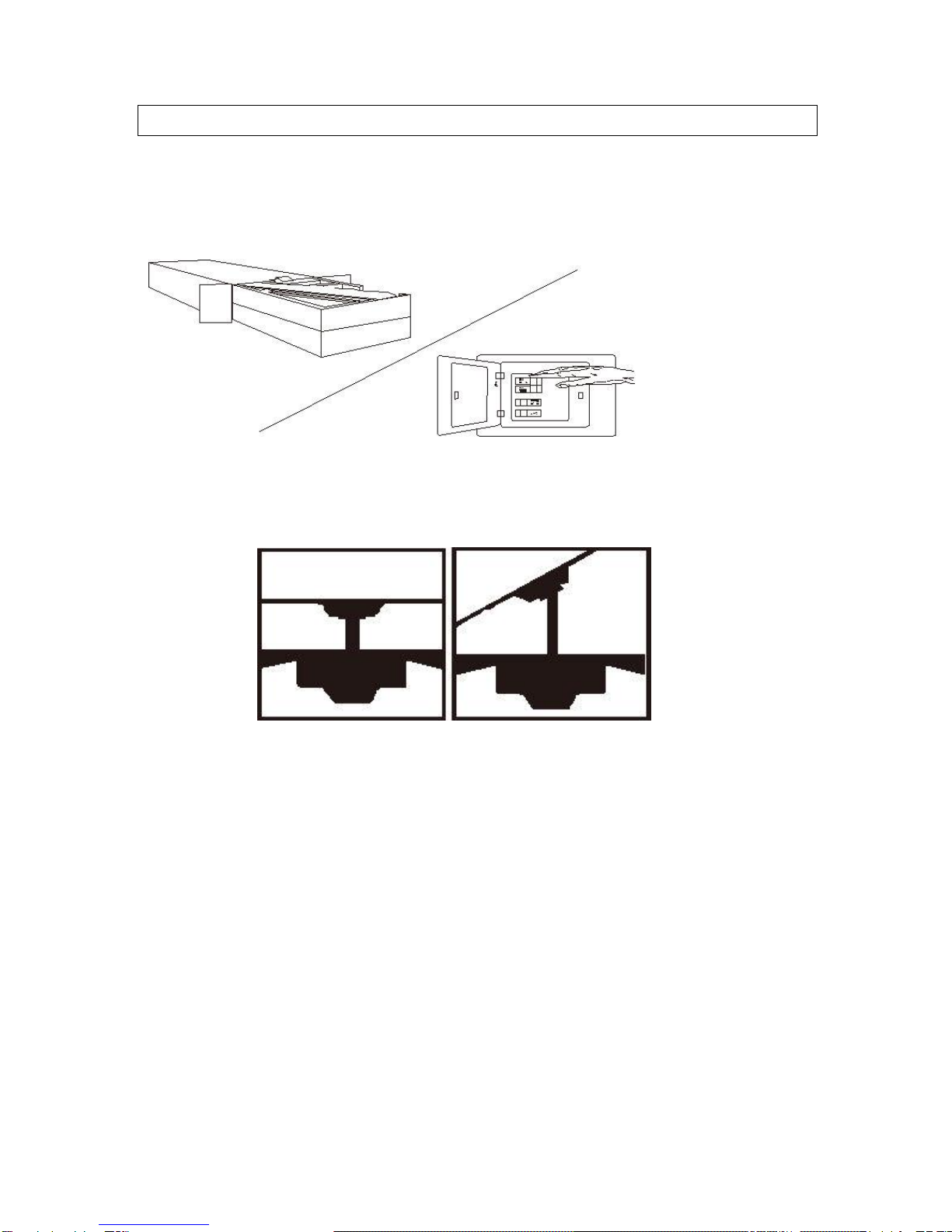
Before you begin installing the fan, switch power off at the service panel and lock service
disconnecting means prevent power from switched on accidently. When the service disconnecting
means cannot be locked, securely fasten a prominent warning device, such as a tag to the service
panel.
If the power supply cord is damaged, contact your local service center or a qualified electrician to
install an appropriate replacement cord to prevent any injury or damage.
The appliance should not be used in locations where special conditions prevail such as the
presence of a corrosive or explosive atmosphere (dust, vapor, gas).
After making wire connection, gently push connections into the outlet box with wire nuts pointing
up. The wires should be spread apart with the grounded conductor and the equipment grounding
conductor on one side of the outlet box and the ungrounded conductor on the other side of the