barbas 90-60 PF2 Operating instructions

Preparation manual
Gas Fire Front 90-60 PF2
---- Floating Frame --------------- Floating Frame + ----
---- Hidden Door --------------------- Hidden Door + ----
Serial number:
Production date:

© Barbas Bellfires BV
This document or parts thereof may not be reproduced, stored in a retrieval system, ortransmitted,
in any form or by any means, electronic, mechanical, photocopying,recording, nor otherwise,
without the prior written permission of Barbas Bellfires BV.This document could contain technical
inaccuracies or typographical errors. Barbas Bellfires BV reserves the right to revise this document
from time to time in thecontents thereof.
Contact information
Barbas Bellfires BV
Hallenstraat 17, 5531 AB Bladel, The Netherlands
Phone: +31 49 733 9200
E-mail: [email protected]
Introduction
2Gas Fire Front 90-60

Contents
1 About this document................................................................................ 4
1.1 How to work with this document.................................................................................................. 4
1.2 Warnings and cautions used in this document............................................................................ 4
1.3 Related documentation................................................................................................................4
2 Overview of the concentric flue system................................................... 5
3 Safety.......................................................................................................6
3.1 Safety instructions for installation................................................................................................ 6
4 Requirements...........................................................................................7
4.1 Requirements on the location...................................................................................................... 7
4.2 Requirements on the convection package (option)......................................................................7
4.3 Other requirements......................................................................................................................7
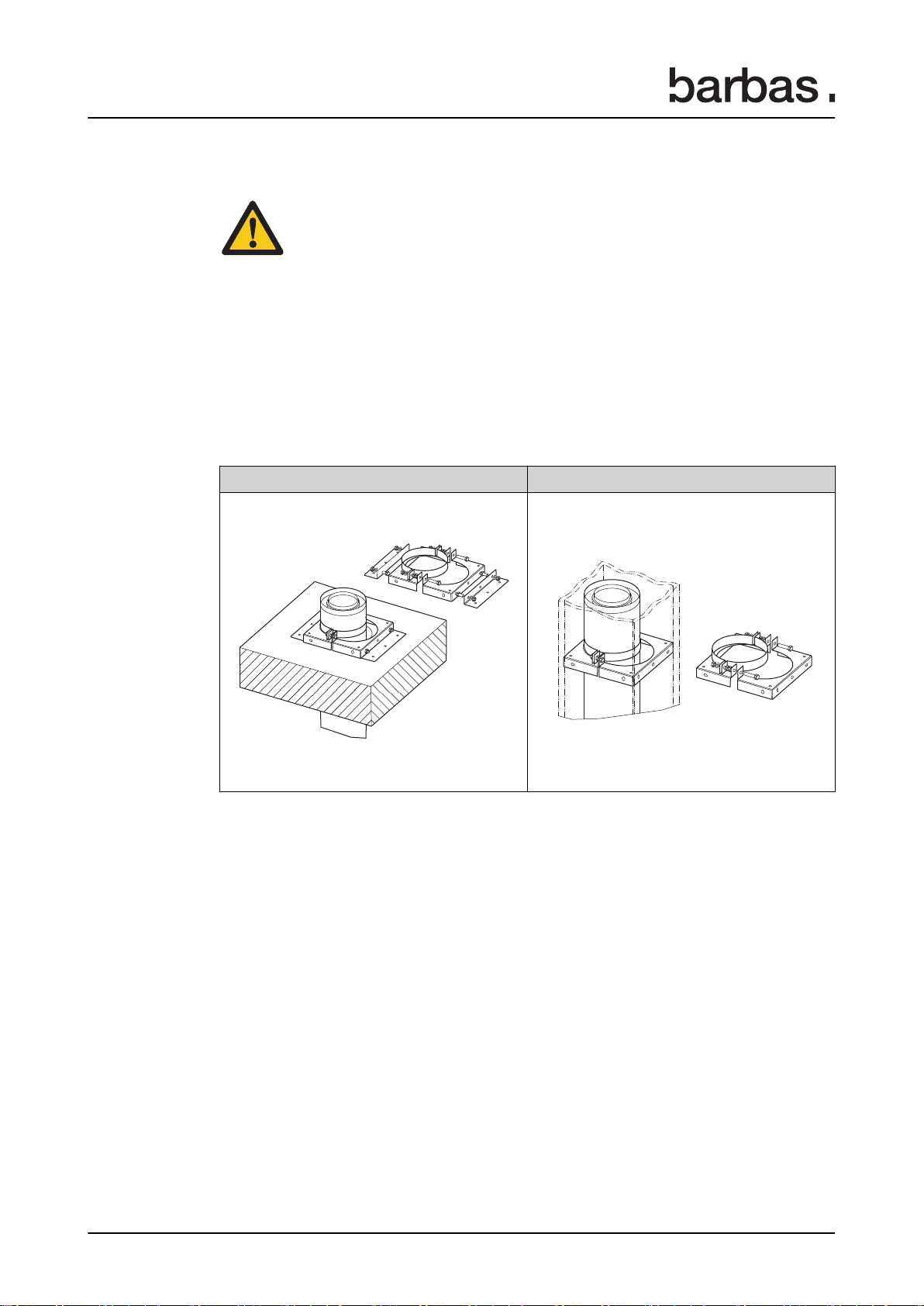
4.4 Requirements on the roof and wall outlet.................................................................................... 8
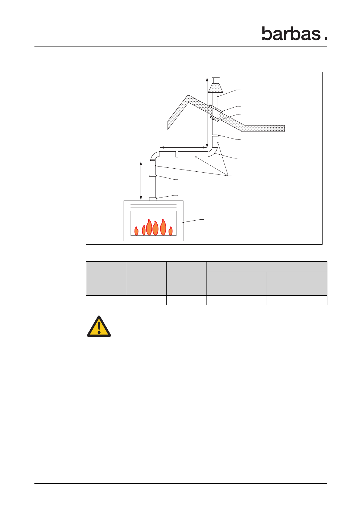
4.5 Requirements on the concentric flue system.............................................................................10
4.5.1 Possibilities for a concentric flue system with a roof outlet............................................. 11
4.5.2 Possibilities for a concentric flue system with a wall outlet............................................. 17
5 Technical specification...........................................................................22
5.1 Gas Fire Front 90-60 PF2 with Floating Frame......................................................................... 22
5.2 Gas Fire Front 90-60 PF2 with Floating Frame +...................................................................... 23
5.3 Gas Fire Front 90-60 PF2 with Floating Frame and adjustable legs......................................... 24
5.4 Gas Fire Front 90-60 PF2 with Hidden Door............................................................................. 25
5.5 Gas Fire Front 90-60 PF2 with Hidden Door +.......................................................................... 26
5.6 Gas Fire Front 90-60 PF2 with Hidden Door and adjustable legs............................................. 27
5.7 Gas Fire Front 90-60 PF2 with Hidden Door and convection casing.........................................28
5.8 Gas Fire Front 90-60 PF2 with Floating Frame + and convection casing..................................29
5.9 Dimensions of the restriction plate.............................................................................................30
6 Available components for the concentric flue system - natural
draught........................................................................................................31
6.1 Appliance part list.......................................................................................................................31
6.2 Bellfires - Muelink & Grol system Ø100 - Ø150......................................................................... 32
6.3 Bellfires - Muelink & Grol system Ø130 - Ø200......................................................................... 38
6.4 Poujoulat - DUOGAS system Ø100 - Ø150...............................................................................42
6.5 Poujoulat - DUOGAS system Ø130 - Ø200...............................................................................45
6.6 Ontop - Metaloterm US system Ø100 - Ø150............................................................................47
6.7 Ontop - Metaloterm US system Ø130 - Ø200............................................................................51
6.8 Jeremias/STB - H-Twin system Ø100 - Ø150............................................................................56
6.9 Jeremias/STB - H-Twin system Ø130 - Ø200............................................................................60
6.10 Jeremias - TWIN-GAS system Ø100 - Ø150.............................................................................63
6.11 Jeremias - TWIN-GAS system Ø130 - Ø200.............................................................................69
6.12 Modinox - PLA system Ø100 - Ø153......................................................................................... 75
6.13 Modinox - PLA system Ø130 - Ø200......................................................................................... 85
Contents
Gas Fire Front 90-60 3

1 About this document
This document shows the necessary information to do these tasks on the Gas Fire Front
90-60 PF2:
• Preparation for installation
This document refers to the Gas Fire Front 90-60 PF2 as 'the appliance'. This document
is an essential part of your appliance.Read it carefully before you do work on the
appliance. Keep it in a safe place.
The original instructions of the document are in English. All other language versions
of the document aretranslations of the original instructions.It is not always possible to
provide a detailed illustration of every single item of theequipment. The illustrations in this
document show a typical setup. The illustrationsare for instructional use only.
1.1 How to work with this document
1. Make yourself familiar with the structure and content of the document.
2. Read the safety section in detail.
3. Make sure that you understand all theinstructions.
4. Do the procedures completely and in the given sequence.
1.2 Warnings and cautions used in this document
Warning
If you do not obey these instructions, there is a risk that can cause personal injury or
death.
Caution
If you do not obey these instructions, there is a risk of damage to the equipment or to
property.
Note
A note shows more information.
Symbol Description
Visual sign that there is a hazard
Visual sign that there is a notice
1.3 Related documentation
• Preparation manual
• Installation and maintenance manual
• User manual
• Assembly instructions for concentric flue system
About this document
4Gas Fire Front 90-60

2 Overview of the concentric flue system
The concentric flue system provides the appliance with combustion air and removes the
flue gases from the appliance. The concentric flue system is made of these items:
Item Description
Concentric flue
The concentric flue is a pipe with an inner pipe. The
inner pipe is used as flue gas channel and the space
between the inner pipe and the outer pipe is used as
combustion air channel
Flue gas channel
The flue gases from the appliance flow through the
channel to the outlet by natural draught or, with the
Opti-Vent installed, forced draught.
Combustion air channel Supplies the appliance with fresh air from the outlet
through the channel
Outlet/terminal Entry for the combustion air channel and exit for the
flue gas channel
Overview of the concentric flue system
Gas Fire Front 90-60 5

3 Safety
3.1 Safety instructions for installation
Caution:
• The appliance must be installed as a 'room sealed system' appliance
by a certified and registered gas installation engineer in accordance with
the supplied installation instructions, and nationally and locally applicable
regulations.
• If you have any questions regarding the installation, consult your local gas
company.
• Before the installation starts, make sure that the details on the rating plate
correspond with the gas type and supply pressure as intended for the
appliance.
• Only use items in the installation that are specified in this manual and the
related documents.
• Only use the following brands for the installation of the concentric flue
system:
Manufacturer System Flue gas extraction
Bellfires Muelink & Grol system Natural draught
Poujoulat DUOGAS system Natural draught
Ontop Metaloterm US system Natural draught
Jeremias/STB (STB =
Schoorsteen Techniek-
Brummen NL)
H-Twin system Natural draught
Jeremias TWIN-GAS system Natural draught
Modinox PLA system Natural draught
Barbas Opti-Vent system 1Forced draught
• Do not use a combination of parts from different brands for the installation
of the concentric flue system.
• All concentric flue systems in this list can be installed with (prefabricated)
building materials that are suitable for T400 or higher.(T400 as described
in the standard: prEN 1856-1; Chimneys - Requirements for metal
chimneys - Part 1: System chimney products ). Concerns building
materials according to DIN 18160 Chimney systems.
1For installation and use of the Opti-Vent system refer to the Barbas manual "installation and mainte-
nance manual Opti-Vent system.
Safety
6Gas Fire Front 90-60

4 Requirements
4.1 Requirements on the location
• Never use combustible building materials for the fireplace.
• Do not install the appliance against a flammable rear wall.
• Install a non-flammable insulation plate of at least 12 mm between the appliance and
a non-flammable rear wall. The insulation plate must cover the entire area of the rear
of the appliance.
• For details about the installation, minimum clearances to flammable materials,
permitted insulation materials and air gaps, refer to the "installation and maintenance
manual".
• If the fire burns in the appliance, make sure that the floor temperatures below and in
front of the appliance cannot be higher than 85 °C .
• Make sure that the room where the appliance is installed is properly ventilated.
4.2 Requirements on the convection package (option)
• The convection outlet opening must be at least 0,5 meter above the appliance.
• No flammable material is present within 10 cm on both sides and 20 cm above the
convection outlet opening.
• The convection outlet opening must be at least 15 cm below the ceiling.
4.3 Other requirements
• The gas supply connection is located near the right side of the appliance for an easy
connection.
• Only use gas piping of at least ½" and a shut-off valve to connect the gas supply to the
gas connection of the appliance.
• Make sure that there is a wall socket with an earth connection nearby the appliance.
The socket must be accessible at all times. The power cable (+/- 0.5 m) is coming
from the right side of the appliance.
• Install the fireplace on a solid floor that can bear the weight of the appliance and the
fireplace.
• If the floor is made of flammable material, take correct safety measures. Install a
temperature protection plate made of nonflammable material between the appliance
and the floor.
• Install the appliance as a built-in appliance in a new fireplace.
• If the concentric flue system is installed in an existing chimney that is used for wood or
coal fire, clean the chimney.
• If you built a new fireplace, make sure that it is ventilated with vents at the bottom and
top of the fireplace. If the fireplace is not ventilated the temperature of the appliance
can increase to dangerous temperatures and damage the fireplace.
• Keep a minimum distance between the appliance and flammable mantelpieces. Refer
to the chapter "Mantelpiece clearances" in the "installation and maintenance manual":
for the correct minimum clearances.
Requirements
Gas Fire Front 90-60 7

4.4 Requirements on the roof and wall outlet
Location of roof and wall outlets
Refer to the table hereunder for explanation of the figure.
Note: All the minimum distances in the table are guidelines. Consult your
national and local regulations for the exact minimum distances.
Requirements
8Gas Fire Front 90-60

Minimum separation distances for roof and wall outlet(terminal) in mm
Location
Minimum
distance
[mm]
A Below an opening 2 on the same wall/roof 2000
B Above an opening 3 on the same wall/roof 700
C Horizontally to an opening 3 on the same wall/roof 700
D Horizontally to a facing opening 3 in a opposite wall 2000
E From a roof terminal under an opening 3 in a nearby rising wall 4000
F Above a flat or pitched roof 300
G Horizontally from a terminal on the same roof 300
H From a structure (e.g. brick chimney) on the roof 300
I Below a roof window in a pitched roof 2000
J Above a roof window in a pitched roof 600
K Horizontally to a roof window in a pitched roof 600
L From an internal or external corner 500
M From a vertical drainpipe or soil pipe 300
NBelow gutters, soil pipes or drainpipes, made of flammable materials 500
Below gutters, soil pipes or drainpipes, made of non-flammable materials 300
OBelow eaves, made of flammable material 500
Below eaves, made of non-flammable material 300
P Below balcony 3 or car port roof 2000
Q Beyond the balcony 4 edge 0
R On either side of a balcony 41500
S Above ground, roof or balcony 4 level 300
T From a surface facing the terminal 500
U From a terminal facing the terminal (at the same height) 600
V From an opening in the car port into the building 1200
W Vertically from a terminal on the same wall 1200
X Horizontally from a terminal on the same wall 300
Y From a boundary alongside the terminal 1000
Z From a boundary facing the terminal 2000
• If the outlet is installed less than 0.5 m horizontally and less than 2 m vertically from a
public area, install an effective protector.
• Make sure that the mesh size of the guard does not effect the operation of the
appliance.
• If the height of the outlet is less than 3 meter from the floor, the distance between the
outlet and a garden or a terrace must be minimum 2 meter.
2An opening here means an element that is permanent open (example: an air vent) or that can open
(example: a door or window). But, in addition, the distance between outlet and built-in elements
(example: window, door) must be minimum 300 mm.
3Balcony or gallery of an apartment building.
Requirements
Gas Fire Front 90-60 9

4.5 Requirements on the concentric flue system
Caution:
• Make sure that no flammable materials are located close to the flue
system. The outer walls of the flue system can be 150 °C.
• Make sure that the concentric flue system is in a casing.
• Make sure that the casing is made of heat resistant material.
• Make sure that air can flow in the casing. Use grates near the floor and
near the ceiling. Do this for every floor where the casing is located.
• Do not insulate the concentric flue.
The parts that are required for the installation of the concentric flue system are numbered
in the illustrations and refer to the part list in
6
.
Use the universal wall/floor support (number 36 in the part list) to attach the concentric
flue system to the casing and/or the floor.
Floor support Wall support
Install a concentric flue system as described in this section.
Some configurations of the concentric flue system require the installation of a flue
restriction plate. Different sizes of the flue restriction plate are delivered with the
appliance. Refer to the Installation and maintenance manual.
Requirements
10 Gas Fire Front 90-60

4.5.1 Possibilities for a concentric flue system with a roof outlet
Rigid concentric flue systems
Note: Refer to chapter
6
for a description of the numbers in the figures.
4,28,(100)
1
10/11/12/13
23
24
17
16
24
18
16
Y
Concentric flue connection on appliance Ø100-Ø150 mm or Ø130-Ø200 mm
Y
(min. - max.)
Flue gas restriction plate width
Concentric connection on the appli-
ance is Ø100-Ø150 mm
Concentric connection on the appli-
ance is Ø130-Ø200 mm
2.0 - 4.0 m 30 mm 65 mm
4.0 - 12.0 m 40 mm 80 mm
Requirements
Gas Fire Front 90-60 11

4,28,(100)
1
10/11/12/13
14,15
17
16
24
23
23
Y1
X
Y2
Concentric flue connection on appliance Ø100-Ø150 mm or Ø130-Ø200 mm
Y1
(min. - max.)
X
(min. - max.)
Y1 + Y2
(min. - max.)
Flue gas restriction plate width
Concentric connection
on the appliance is
Ø100-Ø150 mm
Concentric connection
on the appliance is
Ø130-Ø200 mm
1.0 - 11.0 m 0 - 3.0 m 2.0 - 11.0 m - 40 mm
Caution:
Make sure that Y1 + Y2 is at least 2 times larger than X.
Requirements
12 Gas Fire Front 90-60

Flexible concentric flue systems
4,28,(100)
1
30
32
29
5
7
26
29
23
25
18
10/11/12/13
Y
Concentric flue connection on appliance Ø100-Ø150 mm or Ø130-Ø200 mm
Y
(min. - max.)
Flue gas restriction plate width
Concentric connection on the appli-
ance is Ø100-Ø150 mm
Concentric connection on the appli-
ance is Ø130-Ø200 mm
2.0 - 4.0 m 30 mm 65 mm
4.0 - 12.0 m 40 mm 80 mm
Roof outlet using an flexible Ø100 mm liner in an existing lined chimney.
Requirements
Gas Fire Front 90-60 13

4,28,(100)
1
30
32
29
5
7
26
23
25
29
45°
18
10/11/12/13
Y3
Y1
Y2
X
Concentric flue connection on appliance Ø100-Ø150 mm or Ø130-Ø200 mm
Y1
(min. - max.)
X
(min. - max.)
Y1 + Y2 + Y3
(min. - max.)
Flue gas restriction plate width
Concentric connection
on the appliance is
Ø100-Ø150 mm
Concentric connection
on the appliance is
Ø130-Ø200 mm
1.0 - 11.0 m 0 - 3.0 m 2.0 - 11.0 m - 40 mm
Caution:
Make sure that Y1 + Y2 + Y3 is at least 2 times larger than X.
Roof outlet using an flexible Ø100 mm liner in an existing lined chimney.
Requirements
14 Gas Fire Front 90-60

4,28,(100)
1
31
30
32
29
6
8
7
26,29
27,28,29
18
29
Y
Concentric flue connection on appliance Ø100-Ø150 mm or Ø130-Ø200 mm
Y
(min. - max.)
Flue gas restriction plate width
Concentric connection on the appli-
ance is Ø100-Ø150 mm
Concentric connection on the appli-
ance is Ø130-Ø200 mm
2.0 - 4.0 m 30 mm 65 mm
4.0 - 12.0 m 40 mm 80 mm
Roof outlet using an flexible Ø100 mm liner and flexible Ø150 mm liner in an existing
unsound lined chimney.
Requirements
Gas Fire Front 90-60 15

4,28,(100)
1
30
31
32
29
6
7
8
26,29
27,28,29
45°
18
29
Y3
Y1
Y2
X
Concentric flue connection on appliance Ø100-Ø150 mm or Ø130-Ø200 mm
Y1
(min. - max.)
X
(min. - max.)
Y1 + Y2 + Y3
(min. - max.)
Flue gas restriction plate width
Concentric connection
on the appliance is
Ø100-Ø150 mm
Concentric connection
on the appliance is
Ø130-Ø200 mm
1.0 - 11.0 m 0 - 3.0 m 2.0 - 11.0 m - 40 mm
Caution:
Make sure that Y1 + Y2 + Y3 is at least 2 times larger than X.
Roof outlet using an flexible Ø100 mm liner and flexible Ø150 mm liner in an existing
unsound lined chimney.
Requirements
16 Gas Fire Front 90-60

4.5.2 Possibilities for a concentric flue system with a wall outlet
Note: Refer to chapter
6
for a description of the numbers in the figures.
Install the wall outlet in the correct position as shown in the figure. The centre of the inner
pipe must be positioned above the centre of the outer pipe.
Rigid concentric flue systems
19
1
10/11/12/13
4,28,(100)
14
Y
0.16 m
X
Concentric flue connection on appliance Ø100-Ø150 mm or Ø130-Ø200 mm
Y
(min. - max.)
X
(min. - max.)
Flue gas restriction plate
Concentric connection
on the appliance is
Ø100-Ø150 mm
Concentric connection on
the appliance is Ø130-
Ø200 mm
1.5 - 2.5 m 0 - 0.6 m - -
2.5 - 3.5 m 0 - 1.6 m - -
Requirements
Gas Fire Front 90-60 17

19
1
110/111/113
4,128
14
100
Y
0.16 m
X
Concentric flue connection on appliance Ø130-Ø200 mm
Y
(min. - max.)
X
(min. - max.)
Flue gas restriction plate width
Concentric connection on the appliance
is Ø130-Ø200 mm
0.5 - 1.0 m 0 - 0.6 m -
1.0 - 2.0 m 0 - 2.6 m -
Requirements
18 Gas Fire Front 90-60

19
1
4,128
123
100
Y
0.25 m
X
114
110/111/113
Concentric flue connection on appliance Ø130-Ø200 mm
Y
(min. - max.)
X
(min. - max.)
Flue gas restriction plate width
Concentric connection on the appliance
is Ø130-Ø200 mm
0.5 - 1.0 m 0 - 1.6 m -
1.0 - 3.0 m 0 - 4.6 m -
Requirements
Gas Fire Front 90-60 19

19
1
4,128
114
100
110/111/
113
110/111/113
0.16 m
14
114
110/113
X2
X1
Y1
Y2
Concentric flue connection on appliance Ø130-Ø200 mm
Y1
(min. - max.)
X1
(min. - max.)
Y2
(min. - max.)
X2
(min. - max.)
Flue gas restriction plate
width
Concentric connection on
the appliance is Ø130-
Ø200 mm
0 - 0.5 m 0 - 0.5 m 0.5 - 1.0 m 0 - 0.6 m -
0.5 - 1.0 m 0 - 0.5 m 0 - 0.5 m 0 - 0.6 m -
1.0 - 3.0 m 0 - 1.0 m 0.5 - 2.0 m 0 - 0.6 m -
1.0 - 3.0 m 0 - 3.0 m 1.0 - 3.0 m 0 - 0.6 m -
Requirements
20 Gas Fire Front 90-60
Other manuals for 90-60 PF2
1
Table of contents
Other barbas Stove manuals
Popular Stove manuals by other brands

Palazzetti
Palazzetti ECOFIRE MARISA PRODUCT TECHNICAL DETAILS

Winco
Winco PGS-1K Operating instructions manual

United States Stove
United States Stove CSSU owner's manual

Jøtul
Jøtul Wood Stove Installation and operating instructions

Camplux
Camplux JK-5330 Instructions for installation and use

BORETTI
BORETTI CFBI902IX Instruction on mounting and use